Table of Contents
Advertisement
Quick Links
Advertisement
Table of Contents

Related Manuals for Esko Kongsberg C series


Summary of Contents for Esko Kongsberg C series
- Page 1 Kongsberg C-series User Manual 05 - 2018 | C-series...
-
Page 2: Table Of Contents
Kongsberg C-series Contents 1. Preface................................. 9 2. Change Record............................10 3. Welcome..............................11 4. Using this manual........................... 12 4.1. Main Sections..........................12 4.2. Name Styles and Symbols......................13 4.3. Pictures and Illustrations........................13 4.4. Local Languages..........................14 5. Safety Regulations..........................15 5.1. Introduction............................. 15 5.2. - Page 3 Contents 6.4. Main Power Switch......................... 30 6.5. Operator Panel..........................30 6.6. Traverse Panel..........................34 6.7. Foot Pedal............................34 6.8. High Pressure Air System.......................34 6.9. Application Programs Available..................... 35 7. Basic Operations............................. 36 7.1. Introduction............................. 36 7.2. Power On Sequence........................36 7.3.
- Page 4 Kongsberg C-series 10.9. Reference Points and Coordinate System.................. 56 10.10. Table Speed..........................59 10.11. Table Acceleration........................60 10.12. Jog Settings..........................60 10.13. Set Table Top Reference......................61 10.14. Vacuum Setup..........................61 10.14.1. Vacuum Zone Configuration....................61 10.15. Router Setup..........................63 10.16. Conveyor Belt Control........................ 64 10.16.1.
- Page 5 Contents 12.8.6. Routing Advice........................105 12.8.7. Cleaner Device........................108 12.8.8. Bits and Bit Change......................108 12.8.9. Chuck Change and Cleaning....................110 12.8.10. Bit Slipping, Chuck Change....................114 12.8.11. Bit Length and Position....................114 12.8.12. Tool Adjustment......................115 12.8.13. Table Top and Tool Height Adjustment................ 115 12.8.14.
- Page 6 Kongsberg C-series 14.3. X1 amplifier..........................162 14.4. X2 amplifier..........................163 14.5. Y amplifier............................164 14.6. P1/P2 fuses..........................166 14.7. Tool Rotation/Reciprocating Knife..................... 167 14.8. Chiller1 fuse..........................168 14.9. Heater for Chiller Fuse....................... 169 14.10. Chiller2016 Fuse replacement....................169 14.11. TakeUp Unit, Fuse replacement....................170 15.
- Page 7 19.14. Emergency Stop Solution......................256 20. Vacuum Cleaner..........................258 20.1. Vacuum Cleaner, Zefiro......................258 20.1.1. How to use........................258 20.2. Vacuum Cleaner, High-capacity, TB ESKO.................260 20.2.1. How to use........................260 20.3. Compact Vacuum Cleaner......................263 20.3.1. How to use........................263 21. Install Software........................... 265...
- Page 8 Kongsberg C-series 22.1. Machine............................266 22.2. Tools............................. 266 22.3. iPC..............................267 viii...
-
Page 9: Preface
Kongsberg AS does not warrant, guarantee or make any representations regarding the use, or the results of the use of the system or the information contained herein. Esko-Graphics Kongsberg AS shall not be liable for any direct, indirect, consequential or incidental damages arising out of the use or inability to use the system or the information contained herein. -
Page 10: Change Record
Kongsberg C-series 2. Change Record Description Date dd-mm-yy 03-02-2017 jhbe TakeUp Unit, information added 28-02-2017 jhbe i-BF Board Feeder, information updated 18-04-2017 jhbe Measuring station operation, information added. 20-04-2017 jhbe Braille tool description added 20-04-2017 jhbe Bevel 45 tool adapter description added 04-05-2017 jhbe Never run Milling Unit when TakeUp Unit is... -
Page 11: Welcome
Kongsberg C-series 3. Welcome Welcome to the User Manual for Kongsberg C series running iPC. This manual will provide a complete and detailed description of all Cutting Table functions. There is a separate user manual for i-cut Production Console (iPC). Thus, actual GUI functions will be referenced in this manual, but the complete and comprehensive description is available in the User Manual for i-cut Production Console. -
Page 12: Using This Manual
Kongsberg C-series 4. Using this manual 4.1. Main Sections The manual is divided into the following Main Sections: Safety Regulations • All safety related issues are discussed. System Description • This chapter provides basic knowledge about the machine. Basic Operations •... -
Page 13: Name Styles And Symbols
Kongsberg C-series Tooling System • Tool descriptions. Maintenance • This chapter describes maintenance to be carried out by the customer. Fuse Replacement • Fuse location and specification. Appendices • Roll Feeder - basic information. Vacuum Cleaner • - basic information. 4.2. -
Page 14: Local Languages
Kongsberg C-series 4.4. Local Languages This manual is available in a wide range of local languages. Screen pictures and illustrations remains in English language. -
Page 15: Safety Regulations
Kongsberg C-series 5. Safety Regulations 5.1. Introduction The C-table is designed to conform to Safety Regulation standards. Nevertheless, operating the table can involve hazards if : • The operator does not follow the Operating Instructions • The table is used for non-intended purposes. In addition to the Safety Regulation described below, you will find safety warnings in the respective topics. -
Page 16: Requirements To Be Met By Operators
• Utilizing accessories other than those specified by Esko. Non-intended use may cause: • Health hazards and injuries. • Damage to the system. • Incorrect functionality. • Damage to work materials. Note: Esko is not liable for any damage resulting from such Non-intended use. ... -
Page 17: Warning Sign Explanation
Kongsberg C-series 5.5. Warning Sign Explanation Knife Blades are extremely sharp. This symbol is used in this documentation to indicate operations with Knife Blades and Milling bits. Hand Squeeze Potential areas with a risk of being squeezed are marked with the Hand Squeeze sign. - Page 18 Kongsberg C-series The Main Power Unit (MPU) contains Mains Voltage and may be opened by Authorized Personnel only. The MPU is marked with the High Voltage warning sign. Laser Radiation. The tool head is equipped with a class II Laser Pointer. Avoid laser light into your eyes.
-
Page 19: Attention Areas
Kongsberg C-series 5.6. Attention Areas 5.6.1. Moving Parts, Laser Radiation and High Voltage 5.6.2. Loose Clothing While working with this machine, do not: • Use ties • Use loose necklaces • Use scarfs 5.6.3. Noise Level • Hearing Protection should be used by any personnel exposed to the noise from the machine. -
Page 20: Ejection Of Parts
Kongsberg C-series 5.6.4. Ejection of Parts Potential risk when running HPMU Personnel hit by breaking milling bit or small pieces of processed material. • Eye Protection should be used by any personnel working with HPMU. 5.6.5. i-Camera strobing light If your system includes i-Camera, please read this warning carefully: WARNING i-Camera is equipped with LED strobing light. -
Page 21: Safety Devices
Kongsberg C-series 5.7. Safety Devices 5.7.1. Overview The Main Power Switch Emergency Stop Button Yellow / Black tape on the floor to indicate Attention Area Warning Lamp Dynaguard 5.7.2. Emergency Stop Button... -
Page 22: Yellow / Black Tape
Kongsberg C-series Emergency Stop buttons. Switch positions - Emergency Stop is switched OFF. - Emergency Stop is switched ON; Servo Power to the machine is switched off. Note: Activating the Emergency Stop Button does not provide a guarantee against injury! Due to the high kinetic energy of moving parts, do not underestimate stopping distances of traverse, Y carriage and tool head. -
Page 23: Warning Lamp On Top Of Y Carriage
Kongsberg C-series 5.7.4. Warning Lamp on top of Y carriage Light is Description Servo Power is off Servo Power is on, Safety System is enabled, table is ready for operation Flashing Safety System is activated. Reset Safety System to continue operation 5.7.5. -
Page 24: Protective Equipment
Ensure the Traverse Safety Stop switches are centered. 5.8. Protective Equipment For the operator(s), Esko recommends the following Protective Equipment: Close-fitting clothes to avoid being caught by the beam or the tool head which can cause injuries. Gloves to protect against cuts from materials with sharp edges. -
Page 25: Procedures In Case Of Malfunctions
98.5 dBA. 5.9. Procedures in case of Malfunctions Trouble-shooting and repair shall be executed by Authorized Personnel only. Contact the Esko Service Organization. 5.10. Residual Risk Despite all safety protection means incorporated in this machine, there are some Residual Safety Risks to be aware of:... - Page 26 Kongsberg C-series Y-carriage The top of the Y-carriage is un-protected in all four directions. Actions: • Do not bend down over the table or traverse while the machine is working. Rear side of traverse The DynaGuard Safety System photo cell beam will stop the movement when hit.
-
Page 27: System Description
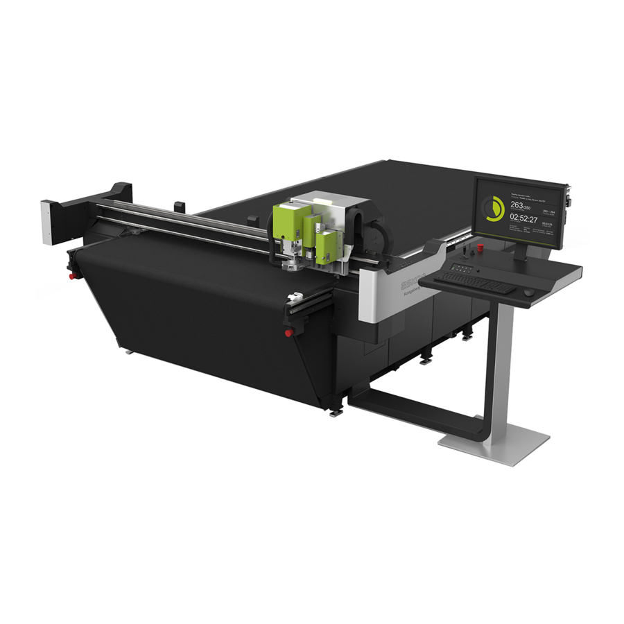
Kongsberg C-series 6. System Description 6.1. Naming Conventions Machine 1 Cutting Table 7 Gallows for HPMU button 2 Traverse 8 Main Power on/off switch 3 Y carriage 9 Operator Panel 4 Tools 10 Operator Station 5 Traverse Safety Stop switches 11 Main Power Unit (MPU) (DynaGuard) 6 Emergency Stop... -
Page 28: Front End Pc
Kongsberg C-series Axes X - X-axis Z1 - Z1 axis. P1 Tool Position. Y - Y-axis Z2 - Z2 axis. P2 Tool Position. X1 - X1 end of traverse X2 - X2 end of traverse 6.2. Front End PC Front End PC, location Open the door... -
Page 29: Operator Station
Kongsberg C-series 6.3. Operator Station Functions 1. Operator Panel 2. Joystick 3. Joystick Pushbutton 4. Main Power Switch 5. Emergency Stop 6. Blowback level adjustment... -
Page 30: Main Power Switch
Kongsberg C-series Drawer A drawer is available on the right side of the station. Note: If the Operator Station is on the X1-side of the table, the drawer is locked. Monitor orientation In order to be visible from any position, the monitor is rotable. USB connections USB connectors are available on the rear side and on the bottom side of the monitor. - Page 31 Kongsberg C-series Servo Power On After June-September 2018 Safety System reset / Servo Power on/off control. After the table power is switched on, the Servo Power lamp will flash. The flashing will stop when the machine is communicating with iPC. Before June-September 2018 Servo Power on/off control.
- Page 32 Kongsberg C-series Press this button to switch Vacuum On/Off. Provides material hold down. Blow Back Press this button to switch between Vacuum and Blow Back. Vacuum - Material hold down. Blow Back - Air pillow on the table to provide easier material handling. Manual Belt Clamp Press and keep this button down for more than 2 seconds: •...
- Page 33 Kongsberg C-series Cancel by pressing Tool Down a second time. No function No function Joystick - Manual Jog Operate the Joystick to move the tool head in the desired direction. The system must be in Pause mode, i.e. the Pause button must be lit, for the Joystick to be operative.
-
Page 34: Traverse Panel
Kongsberg C-series 6.6. Traverse Panel Traverse Panel has the same functionality as the on the Operator Station. Operator Panel 6.7. Foot Pedal Use the Foot Pedal to activate the Conveyor belt clamp and Feeder paws. To be used as an aid when entering roll based material onto the table. -
Page 35: Application Programs Available
Kongsberg C-series The compressed air input is connected to a combined Pressure Regulator Valve/Water Trap. Wall Outlet - Wall Outlet A - Air Tube R - Pressure Regulator Valve P - Pressure Gauge W - Water Trap T - Air Tube to Tools and Valves For details regarding air supply requirements, see Site Preparation Manual. -
Page 36: Basic Operations
Kongsberg C-series 7. Basic Operations Keep away from Moving Parts during operation. Do not lean on Racks, Guide Ways or Traverse during operation, as this may cause personal injury. Before starting any operation, make sure that: • The Table is free from obstructions •... - Page 37 Kongsberg C-series The Warning Lamp on top of the Y carriage is flashing, indicating that the safety system is not reset. Use the mouse, double-click the icon for iPC. Check that no error message indicates faulty conditions. Observe Servo Power lamp is now switched off. Servo Power/Safety Reset Press the Servo On push button.
-
Page 38: Reset Safety System
Kongsberg C-series The Warning Lamp on top of the Y carriage must be on without flashing. Table Zero Sequence Press Start to complete the Table Zero Sequence. The machine will move to the Selected Reference Point. The table is now ready for operation. 7.3. -
Page 39: Continue After Safety Break
Kongsberg C-series To switch off the PC, use the Operating System shutdown procedure.. 7.5. Continue after Safety Break If the Safety System is activated, all movements on the table are stopped and the Warning Lamp starts flashing. To continue operation, proceed as follows: After June-September 2018 Ensure the table is free from obstructions and ready for operation. - Page 40 Kongsberg C-series...
-
Page 41: Prepare For A Job
Kongsberg C-series 8. Prepare for a Job 8.1. Introduction Keep away from Moving Parts during operation. Do not lean on Racks, Guide Ways or Traverse during operation, as this may cause personal injury. Before starting any operation, make sure that: •... -
Page 42: Production Setup
Kongsberg C-series 8.4. Production Setup Opened Job->Production Setup. Verify correct Production Setup: • Number of Copies • Accuracy/Speed Prioritization • Select Reference Point and Job Position • Step and Repeat • Registration • Material Handling • Tool Head Parking 8.5. Speed Setting Opened Job->Production Setup->Quality. -
Page 43: Job Execution
Kongsberg C-series Select Vacuum Zones that corresponds to the outline of your material. Proper selection is important to achieve the best possible material hold down. 8.8. Job Execution Before execution, check this: Verify that Opened Job is ready for production. Verify that the Table View display of the Job is reasonable. -
Page 44: Corrugated Production
Corrugated Production without Registration Marks is straight forward following the Prepare for a Job procedure described in the - chapter. Recommended tooling is described in Esko Tooling Guide. 8.10. Milling Production Milling Production without Registration Marks is straight forward following the procedure described in the Prepare for a Job - chapter. -
Page 45: How To Procedures, Advanced
Kongsberg C-series 9. How To Procedures, Advanced 9.1. Cutting Thick Materials When preparing materials with thickness between 45 – 50 mm (1¾ - 2 in.), the following rules apply: • No Camera operations are available. • Disable Measure Material Thickness. •... -
Page 46: Multi Pass Creasing Or Milling
Kongsberg C-series 9.3. Multi Pass Creasing or Milling 1. pass 2. pass 3. pass - mill through and clean the path Multi Pass Creasing is beneficial if you want a deeper crease path. This is achieved by running one pass with for example 50% depth and a second pass with 70% depth. -
Page 47: Jobs Including Reverse Operations
Kongsberg C-series 9.4. Jobs including Reverse Operations Step 1 - the sheet is aligned towards the Right Step 2 - the sheet is aligned towards the Left Ruler. Ruler. Reverse Operations are completed. The rest of the job is completed. A typical use of Reverse Operation is when you want to add a crease line on the front side of a material that you normally prepare from the rear side. -
Page 48: Work With Different Reference Point Settings
Kongsberg C-series 9.5. Work with different Reference Point Settings Select the Reference Point to use from: Opened Job->Production Setup->Position->Reference Point For more information, go here. 9.6. MultiZone Production Introduction In User Manual for i-cut Production Console, general information about MultiZone Production is available. - Page 49 Kongsberg C-series • 1 - Ready Lamp • 2 - Ready Button • 3 - Vacuum on Button • 4 - Vacuum Lamp Vacuum Zones Vacuum Zone Configuration on page 61 MultiZones The illustration shows the most actual zones available for MultiZone Production. Limitations Work Areas on a MultiZone table...
-
Page 50: Multizone, Workflow
Kongsberg C-series A standard Cutting Table prepared for MultiZone Production, has a limitation caused by the size of the last section, as can be seen by the illustration. SeeWork Area table below. 1680x3200 Work area 2210x3200 3210x1600 3210x3200 3210x4800 66x126 in mm/in 87x126 126.37x63... - Page 51 Kongsberg C-series - Attention Area. During operation in one zone, parts of the traverse will move into the other zone (photo cell beams, traverse end cover). To ensure a continous workflow, the operator should be very careful inside the Attention Area, not to trigger the safety system by his body or by material in and out.
-
Page 52: System Setup
Kongsberg C-series 10. System Setup 10.1. Introduction This chapter will explain functions and parameters that are important for the C system to run properly. It is a supplement to the information available from the User Manual for i-cut Production Console. Examine each step carefully to ensure proper settings: One time adjustments completed at the factory The functions are included here as a reference. -
Page 53: Adjust X1 To X2 Angle
Kongsberg C-series Set Table Speed Set Table Acceleration Jog Settings Set Table Top Reference Conveyor Belt Control Board Size 10.2. Adjust X1 to X2 Angle Machine Connection->Machine Configuration->Installation_>Adjust X1 to X2 Angle Use this wizard to obtain correct angle between X axis and Y axis. Typical use is after maintenance or repair. -
Page 54: Register Table Size
Kongsberg C-series 10.3. Register Table Size Machine Connection->Machine Configuration->Installation_>Register Table Size This wizard moves the Tool Head from edge to edge of the Cutting Table in order to measure the table size. Typical use is after maintenance or repair. Procedure: 1. -
Page 55: Set Main Reference Point
Kongsberg C-series 10.6. Set Main Reference Point Machine Connection->Machine Configuration->Installation_>Set Main Reference Position Follow instructions from the wizard. Use this wizard to establish the Main Reference Point (R). Typical use is after maintenance or repair, if the Main Reference Point has been accidentially moved. -
Page 56: Calibrate Foot On Measuring Station
Kongsberg C-series Procedure: 1. If the table is equipped with a Conveyor Belt, move the belt junction away from the table surface. 2. Execute the Map Table Top function. 3. Follow the instructions given by the wizard. Note: iPC 2.1: The mechanism of compensating Z height during cutting, based on table top mapping, has been disabled when cutting underlay has been measured to be more than 5mm. - Page 57 Kongsberg C-series All X and Y coordinates in the Input File have the selected Reference Point as origin. Two modes of operation are available: • Using Main Reference Point • Using User Defined Reference Point The Main Reference Point position The Main Reference Point is a fixed position on the Cutting Table marked as a cross of drilled holes.
- Page 58 Kongsberg C-series User Defined Reference Points You can specify User Defined Reference Points. User Defined Reference Points are used if you want your job positioned in a fixed position on the table (Rx), but not in the Main Reference Point (R). A special version of User Defined Reference Point is the Panel Reference Point.
-
Page 59: Table Speed
Kongsberg C-series Rulers and Reference Points The Ruler System ensures an easy and correct positioning of the material on the table. The Main Reference Point shall be defined dr = 10 mm/0.39 in. inside the ruler. When you use the Right Ruler, the Reference Point will automatically be moved to an identical distance from the Right Ruler, as it is defined from the Left Ruler. -
Page 60: Jog Settings
Kongsberg C-series Opened Job->Production Setup->Quality Here you specify if this is a High Quality Job or High Speed Job. 10.11. Table Acceleration Menu Bar->Advanced->Configure Tools...->Acceleration This is the default value for each tool when Layers are created. Note: Acceleration can be reduced to a % value of the maximum acceleration available. -
Page 61: Set Table Top Reference
Kongsberg C-series 10.13. Set Table Top Reference Menu Bar->Machine->Set Table Top Reference Follow instructions from the wizard. Machine Connection->Machine Configuration->Installation_>Table Top Reference Follow instructions from the wizard. Machine Panel Toolbar->Table Top Reference Use this function to complete a Tool Height Reference calibration. The Tool Height is measured in current position and the reference to the table top surface is updated. - Page 62 Kongsberg C-series This is a dialog where the Vacuum Zone Configuration for the actual machine is specified. This setup is a one-time job as long as the Vacuum Zone Solution on the machine remains unchanged. The setup should correspond to the actual hardware. The selected setup will determine which Vacuum Zone Configuration that will be available in the User Interface.
-
Page 63: Router Setup
Kongsberg C-series Machine Zone Configuration Vacuum Configuration C64/C66 10.15. Router Setup Machine Connection->Machine Configuration->HW Configuration->Router Setup From the Router Setup dialog, maintain the following parameters: Specify Router If a Router is mounded, spedify Router Type. If no Router is mounted, select None COM-port The physical COM-port used for communication with the Router Control Unit is specified. -
Page 64: Conveyor Belt Control
Kongsberg C-series 10.16. Conveyor Belt Control Machine Connection->Machine Configuration->HW Configuration->Conveyor Specify if the machine is equipped with Conveyor Belt. 10.16.1. Split Sheet Feed Sheet in Load Position Sheet Load, step 1 Sheet Load, step 2 In some occasions, the sheet unloaded from the cutting table can trigger the photo cell safety system. -
Page 65: Board Size
Kongsberg C-series 10.17. Board Size Not implemented yet... -
Page 66: Tool Configuration And Adjustment
Kongsberg C-series 11. Tool Configuration and Adjustment Machine Connection->Tool Configuration The Tool Configuration dialog is used for all tool settings and adjustments. Select tool and function. 11.1. Tool Configuration The C-machine offers two different tool positions, P1 and P2, where different interchangeable tools can be mounted. -
Page 67: Tool Names
Kongsberg C-series P1 - P1 tool position, see table below C – Camera position P - Pen / Drill / Ink Tool holder position P2 - P2 tool position, see table below The following tool configurations are available: Tool Type Available Tool Inserts HDU - Heavy-Duty Unit HD Crease, V-notch Knife, HD Knife... -
Page 68: Adjust Active Tool
Kongsberg C-series The mounted tools are maintained by: Machine Connection->Tool Configuration Current tool configuration is displayed under Identified tools. When a new tool is inserted, it will be identified to the system automatically. By default the system creates a username from the tool type and its serial number. E. g. a knife with serial number 3020 will be named Knife 20 User Tool Name Menu Bar->Advanced->Configure Tools... - Page 69 Kongsberg C-series 1. In the Configure Tool dialog, select the Tool to be adjusted. 2. Press theAdjust Active Tool button to enter the Wizard Selection dialog. 3. Select Lag Settings 4. Follow the instructions given to enter correct values. 5. Repeat the procedure for all rotating tools. Lag Test Machine Connection->Configure Tools->Adjust Selected Tool->Lag Settings->Lag Test...
-
Page 70: Tool Height Calibration
Kongsberg C-series 11.5. Tool Height Calibration Machine Connection->Configure Tools->Adjust Selected Tool->Tool Height Calibration Follow instructions from the wizard. C systems are equipped with Automatic Tool Height Calibration. Thus, the system will run without any manual height calibration. If you would like to add an offset to the measured height, use the Tool Height Calibration dialog: 1. -
Page 71: Center Offset Adjustment
Kongsberg C-series 1. Select the Tool to be adjusted. 2. Press the Adjust Active Tool button to enter the wizard selection dialog. 3. Select Rotation adjustment. 4. Follow the instructions given by the wizard, step by step. 5. Repeat the procedure for all Tools mounted. Manual Adjustment Machine Connection->Configure Tools->Adjust Selected Tool->Manual Adjustment of... -
Page 72: Tool Offset
Kongsberg C-series 1. Put an appropriate test material, that means a thin paper on the table (any significant material thickness will create a misleading offset in this wizard), and switch vacuum on. 2. Select the Tool to be adjusted. 3. Press the Adjust Active tool button to enter the wizard selection dialog. 4. -
Page 73: Maintain Tool List
Kongsberg C-series The Laser Pointer is the reference: 1. Place an appropriate test material on the table, and switch Vacuum On. 2. From Machine Connection->Tool Configuration, select one Tool. 3. Press Adjust Active Tool to enter the Wizard Selection Dialog. 4. - Page 74 Kongsberg C-series Add Tool Use Add Tool to • Add new Tools • Add tools that fails during Automatic Tool Detection The Tool is added to the Tool List.
-
Page 75: Tooling System
Kongsberg C-series 12. Tooling System 12.1. Introduction Knife Blades are extremely sharp. Take care when handling Knife Tools. Laser Radiation. Do not stare into beam! The tool head is equipped with a class II laser pointer. Emitted laser power < 1 mW. In this chapter, all tools are explored: •... -
Page 76: How To Replace A Tool
Kongsberg C-series 12.3. How to Replace a Tool When mounting a tool onto the P1 or P2 Tool Positions, ensure that the Guide Pins and the electrical connector fits those on the bracket. Use an Allen Key, 6 mm, to fix the tool. -
Page 77: Measuring Station
Kongsberg C-series Tool Number Tool Board switch setting Tool 1 1 & 2 off Tool 2 1 on & 2 off Tool 3 1 off & 2 on Tool 4 1 & 2 on Note: There are some restrictions, see Technical Manual for more information. 12.5. -
Page 78: Hdu - Heavy-Duty Unit
Kongsberg C-series • During the first Table Zero Sequence after Power On. • After any Tool change and the Tool is not calibrated. • After the Safety System has been broken for 30 sec. or more. • After the Servo System has been off for 30 sec. or more. •... -
Page 79: Crease Wheel Ø150 Mm
Kongsberg C-series In addition, the Tool Head can be equipped with a ø150 mm Crease Wheel, crease adapter and perforation wheel. For detailed description, see separate chapters for • V-notch Knife • HD knife tools ø150 mm Crease Wheels • •... - Page 80 Kongsberg C-series Insert / remove the Cotter Pin. Tool Adjustment For this tool, complete the following adjustments: Adjustment Description Lag Setting The Lag value depends upon the Blade Adapter. Nominal value is 0 mm. Tool Height Measured automatically, possible to add an Offset Value. Tool Rotation Adjust Tool Angle tangential to Moving Direction.
-
Page 81: V-Notch Knife Tool
Kongsberg C-series 12.6.2. V-notch Knife Tool Description The V-notch Knife Tool mounted on a Heavy-Duty Unit. How to insert / remove the V-notch Knife Tool 1 Turn the V-notch Knife Tool correctly to fit the Guide Pin. - Page 82 Kongsberg C-series 2 Insert the two Latch Pins. 3 Insert the Cotter Pins. How to replace a Knife Blade This picture shows how the Knife Blade is aligned using two Guide Pins (a and b) beneath the blade clamping. 1. Loosen the two screws (b) of the Knife Blade clamping.
- Page 83 Kongsberg C-series • For optimal result, a fine tuning of the adjustments in the actual material should be carried out. For this Tool, complete the following adjustments: Adjustment Description Lag Setting The Knife Lag depends upon the Blade Adapter. Nominal value is 0-7 mm. Tool Height Measured automatically, possible to add an Offset Value Tool Rotation...
- Page 84 Kongsberg C-series Different angles A wide range of V-notch knives is available, providing different knife angles, v: 15 , 22.5 , 30 , 45 , 47.5 V-notch Knife Tool, Modes of Operation Opened Job > Layers Tab > Edit Layer Menu Bar->Layer->Edit Layer...
- Page 85 Kongsberg C-series Single Cut Double Cut This is the default mode if neither Single Cut nor Triple Cut are enabled. Triple Cut Function To ensure proper folding of rigid materials, use this function to remove material from the middle of the cut. Note: •...
- Page 86 Kongsberg C-series When the knife angle is 45 and you cut through the material, the width of the cut is W = 2 x h. Folding If you prepare a material for folding, the following rules applies: • Adjust the cutting depth to just above the bottom liner. •...
-
Page 87: Hd Knife Tool
Kongsberg C-series 12.6.3. HD Knife Tool Description The HD Knife Tool mounted on HDU. The HD Knife Tool is used for rigid board such as ReBoard and Triple Wall material. The Tool is limited to Straight Lines longer than 50mm (2”). The Tool is prepared for special, trapezoid shaped Knife Blades. - Page 88 Kongsberg C-series Use these two screws to fix / release the Knife Blade. How to insert / remove the HD Knife Tool 1 Turn the HD Knife Tool correctly to fit the Guide Pin. 2 Insert the two Latch Pins. 3 Insert the Cotter Pins.
-
Page 89: Crease Adapter
Kongsberg C-series Adjustment Description Nominal value is 10 mm. Tool Height Measured automatically, possible to add an Offset Value. Tool Rotation Adjust Tool Angle tangential to Moving Direction. Center Offset Adjust Tool sideways until centered. Tool Offset Adjust offset relative to Laser Pointer. For more information about how to run the Adjustment Wizards, see the Tool Configuration chapter... - Page 90 Kongsberg C-series Use Perforation Wheel to prepare perforation lines at high speed. Suitable for corrugated board up to C flute (4 mm/0.16 in.). Perforation Wheel assembly Parts in assembly Ensure the path is clean. Fix cover properly.
-
Page 91: Bevel Knife 45
Kongsberg C-series Push / pull the perforation wheel in / out from the adapter. Tool Adjustment For this tool, complete the following adjustments: Adjustment Description Lag Setting The Lag value depends upon the Blade Adapter. Nominal value is 0 mm. Tool Height Measured automatically, possible to add an Offset Value. - Page 92 Kongsberg C-series How to replace a Knife Blade • Loosen the two screws holding the blade clamp. • Pull out the old Knife Blade. • Insert the new blade. • Ensure the blade align exactly with the alignment pins. • Fix the blade clamp. At left, the clamp is removed just to show how to align the Knife Blade.
-
Page 93: Foam Knife
Kongsberg C-series 12.7. Foam Knife Description The Foam Knife Tool Head is mounted onto the P1–position. Note: Be careful where to place the Foam Knife Tool when not in use. If the Tool Head is left on a table surface, the Knife Blade might be exposed, as the material hold down wheels moves up. - Page 94 Kongsberg C-series When not in use, protect the Knife Blade using the handle. How to replace the Knife Adapter Loosen the fixing screw, replace the adapter and fix it again. No additional adjustments are necessary, as the tool height is measured automatically. Disable Material Thickness Measurement Opened Job->Layers->Edit Layer.
-
Page 95: Hpmu - High Power Milling Unit
Kongsberg C-series Adjustment Description Lag Setting The Knife Lag depends upon the Blade Adapter. Nominal value is 3 (5) mm. Tool Height Measured automatically, possible to add an Offset Value. Tool Rotation Adjust Tool Angle tangential to Moving Direction. Center Offset Adjust Tool sideways until centered. - Page 96 Kongsberg C-series HPMU chucks Different chucks are available from http:// www.esko.com/en/store/kongsberg-bits-blades/ Replacing a chuck Replacing a chuck is described in detail in Chuck Change and Cleaning on page 110. This chapter is included just to remind you how important it is to use the Chuck Changing...
-
Page 97: Tool Head Description
Kongsberg C-series 12.8.2. Tool Head description 1. Suction House with brush for chip removal. During normal operation, the house is in down position. When changing bit, the house should be locked in its upper position. 2. Air Blow adjustment. Air Blow is used for Router Bit cooling and to ease chip removal. - Page 98 Kongsberg C-series HPMU Park Position A HPMU Park Position is available on the gallows stand. Use the park position for safe HPMU Tool Head storage. Note: For safety reasons, always insert a Dummy Bit when parking. Lift HPMU in / out of Park Position 1.
-
Page 99: Hpmu With No-Gallows Solution
Kongsberg C-series Suction House, adjustable height On HPMU, you can lock the Suction House in any height; still, it is allowed to move upwards. This function is useful in order to: 1. Adapt to different material thicknesses. 2. Allow false air input in order to reduce suction force. -
Page 100: Safety Issues
Kongsberg C-series All HPMU connections are available on the left The suction tube is fixed using magnetic force. side of Y-carriage. To release, slightly twist the connector. Cooling Water Connections Note: Small droplets of liquid could appear as the cooling water tubes are connected / disconnected. - Page 101 Kongsberg C-series • Ensure the filter inside the Vacuum Cleaner is cleaned regulary. • Be aware the risk of suction tube clogging. • Be aware the risk of suction house clogging. • Milling MDF or other fine dust materials requires extra attention in order to keep the Vacuum Cleaner filter clean.
-
Page 102: Precautions
Kongsberg C-series Router bits are very sharp – handle with care. Never touch a rotating bit. Ensure the warning lamp is dark, and also observe that the bit is not rotating before approaching the bit. Always insert a dummy bit before dismounting a tool head from the machine. High temperatures Be aware it is normal that the HPMU appears to be hot during operation. - Page 103 Kongsberg C-series Keep distance d small For best performance and minimum wear, do not let the bit extend out from the chuck more than necessary. Use bits with short cutting lengths for thin materials. Chuck Open/Close valve operation Never operate the Chuck Open/ Close Valve while the Spindle is running.
- Page 104 Kongsberg C-series Maintain Bit Clamping Un-proper bit clamping may cause the bit to slip in the chuck and damage the Table Top. 1. Keep the bit shaft clean. 2. Avoid greasy fingers. 3. Clean the bit shaft with acetone if necessary, but use only dry cotton tips on the chuck.
-
Page 105: Routing Advice
Kongsberg C-series Note: When replacing a Spindle, torque the motor clamp to 5 Nm, 44 lbf-in using a Torque Wrench. This is a low torque for that screw size. Also check by hand that the Spindle rotates smooth without any resistance. Empty Vacuum Cleaner in time 1. - Page 106 Kongsberg C-series For best performance and minimum wear, do not let the bit stick out more than necessary. Never use higher RPM than recommended by the bit supplier. Special care should be taken when using bits with cutting diameter larger than shank diameter. Bits with small cutting diameter (3-4 mm;...
- Page 107 Kongsberg C-series Acrylic Bits or Multi Purpose Bits 1. Acrylic Bits (A) are polished, extra sharp for acrylic, wood etc. 2. Multi Purpose Bits (MP) have a higher wear resistance, and are suitable for aluface, plastics, MDF, plywood, wood etc. Multi Purpose Bits can be identified by a small tooth at the tip (left hand bit on the picture).
-
Page 108: Cleaner Device
Kongsberg C-series Using other tools in combination with the HPMU It might be necessary to reduce the acceleration in order to achieve an optimal Cutting Quality when combining a heavy tool head with high quality cutting tools. 12.8.7. Cleaner Device Cleaning the suction house is simple using a Cleaner Device, which is available as an option. - Page 109 Kongsberg C-series Observe that the Router Bit is not rotating. Use a cloth to hold the bit. Move the Chuck Open/Close lever down to open the Chuck. Put the bit in a proper storage container. Insert a new Router Bit. Close the Chuck Only the round part of the shaft should be inside the Chuck.
-
Page 110: Chuck Change And Cleaning
Kongsberg C-series Regularly, perform a Chuck cleaning, following the dedicated procedure; Chuck Change and Cleaning on page 110. Note: Never use Compressed Air for cleaning. If a Milling Bit is stuck If a Milling Bit is stuck in the chuck, the probable cause is low air pressure. To release a Milling Bit from the chuck, a pressure of 7 bar is required. - Page 111 Kongsberg C-series Place the Tool Head on the table. Open the chuck and remove any bit. Note: Never apply Compressed Air for cleaning. Apply the 17 mm key to hold the Spindle Rotor. Note: Do not turn the rotor when Chuck is in open position.
- Page 112 Kongsberg C-series Hold the rotor with the 17 mm key and unscrew the chuck using the Chuck Tool. If the bit is stuck, hold the rotor with the 17 mm key and unscrew with a 12 mm key. Note: Tool Open must be pressurized. Use the Taper Brush to clean the Taper.
- Page 113 Kongsberg C-series The Taper Brush must be absolutely free from grease or oil. If necessary, you must clean it with alcohol before you use it. This is very important, as it has direct consequence for the clamping force. Apply small quantities of grease to the threads of the chuck, and to the outer cone and cylindric surface of the chuck (green arrows).
-
Page 114: Bit Slipping, Chuck Change
2. Bit vibrations. When replacing the chuck, follow instructions in Chuck Change and Cleaning on page 110. New chucks are available from Esko store. 12.8.11. Bit Length and Position Keep distance d small. For best performance and minimum wear, do not let the bit stick out more than necessary. -
Page 115: Tool Adjustment
Kongsberg C-series For proper clamping, keep distance e 20 mm, 0.8 inch, as a minimum. To achieve material through-cut, the distance d must be at least 18 mm/0.7 inch. Balanced Bits Bits with balanced surface should have a clamping length f of min. 20 mm/0.8 inches. Maximum balancing length g is 12 mm/0.5 inches. -
Page 116: Miscellaneous
Kongsberg C-series U = Milling Underlay The Table Top Reference function is carried out on top of the Milling Underlay The Tool Height is measured automatically. If, after a test cut, you want to modify the Milling Depth, this is possible from the Tool Height Adjustment dialog. -
Page 117: Lubricool
Kongsberg C-series This takes 20 minutes. Suction House Clean the Suction House when necessary. Use acetone and a q-tip. A smooth surface will ease the chip removal. Vacuum clean the Milling Underlay The Vacuum Cleaner can be used for automatic cleaning of the felt mat: Prepare program to make a file that covers the actual area. - Page 118 Kongsberg C-series LubriCool mounted on HPMU. • A - inspection window. • B - Suction cup with nozzles. LubriCool control unit How to use LubriCool is on when the Vacuum Cleaner is For materials where lubrication is not suitable, use the ON/OFF switch on the LubriCool Control Unit to switch off lubrication.
- Page 119 Kongsberg C-series Inspection Opening When the LubriCool unit is on, you can see light in the control relays inside the unit. For LubriCool, use this oil only: Accu-Lube LB-5000 Use Nozzle Unit or Suction Ring Nozzle Unit Suction Ring...
- Page 120 Kongsberg C-series HPMU is delivered with one Nozzle Unit for the LubriCool function and one Suction Ring with just a brush, and with bigger suction opening. • Use the Nozzle Unit when the LubriCool function is beneficial only! • For all other materials, especially MDF, use the Suction Ring! Note: It is crucial for proper operation that these guidelines are followed.
-
Page 121: Chiller No 1 For Hpmu
Kongsberg C-series Proper cleaning is crucial for correct operation. • Release locker A and remove the nozzle unit. • Use vacuum cleaner to clean the HPMU suction house. • Use vacuum cleaner to clean the nozzle unit. 12.9. Chiller no 1 for HPMU 12.9.1. -
Page 122: Chiller Heater, Operation
Kongsberg C-series 12.9.2. Chiller Heater, Operation Notes: 1. The Chiller Heater is optional. 2. The Chiller Heater must be filled with water before connecting mains. 3. The Chiller Heater is correctly configured when shipped from the factory. Normally, there is no need for modifications. Some operating instructions are included here if any modifications are still needed. -
Page 123: Chiller, Error Conditions
Kongsberg C-series Press Menu button to confirm selection. Programs available Program Temperature range Temperature range Hysteresis from ( to ( Frost protection Factory Setting Correct factory setting is Program = 5 and temperature = 26 oC (Chiller with heater). 12.9.3. Chiller, Error Conditions One common error signal is routed from the Chiller system to the inverter and further into the control system. -
Page 124: Chiller2016 For Hpmu
Kongsberg C-series Code Description Temperature of cooling medium too low During normal operation, the cooling medium temperature is displayed. More information is available from the Operating instructions for the chiller. 12.10. Chiller2016 for HPMU 12.10.1. Introduction Specifications Dimensions W x D x H = 480 x 580 x 430 mm / 19 x 23 x 17 Weight Empty: 40 kg / 88 lbs. -
Page 125: Startup
Kongsberg C-series 12.10.2. Startup Ensure the following pre-requisites are in place for correct startup: • Note: Never start the chiller without liquid. • Signal cable (to inverter) is connected to the chiller unit. • Chiller fluid level should be MAX. If not, fill with fresh water. •... -
Page 126: Vibracut
Kongsberg C-series During normal operation, the cooling medium temperature is displayed. If any chiller failure occurs: • Alarm signal is generated. • Chiller will stop. • Look at the chiller display to see the real reason for the problem: Code Description Water level or water flow too low. - Page 127 Kongsberg C-series Running with 6000 RPM and amplitude +/- 0.15 mm (0.006 inches), this tool is recommended for light duty Corrugated Materials. HF VibraCut (High Frequency VibraCut) Running with 12000 RPM and amplitude +/- 0.6 mm (0.024 inches), this tool is recommended for more demanding Corrugated Materials.
- Page 128 Kongsberg C-series Loosen the screw A and replace the Knife Blade. Ensure the Knife Blade has correct position relative to the screw. Push the Knife Blade down while the screw is fixed. Extreme care should be taken when inserting the Knife Foot again. Keep fingers away from Knife Blade as illustrated at left.
-
Page 129: Rigid Material Knife (Rm Knife Tool)
Kongsberg C-series 12.12. Rigid Material Knife (RM Knife Tool) Replace Knife Blade Use a 3 mm Allen key to fix / loosen the Knife Blade. Ensure the Knife Blade is correctly aligned. No additional adjustments are necessary, as the tool height is measured automatically. Tool Adjustment... -
Page 130: Hiforce Knife
Kongsberg C-series For this tool, complete the following adjustments: Adjustments Description Lag Setting The Knife Lag depends upon the Blade Adapter. Nominal value is 0-4 mm. Tool Height Measured automatically, possible to add an Offset Value. Tool Rotation Adjust Tool Angle tangential to Moving Direction. Center Offset Adjust Tool sideways until centered. - Page 131 Kongsberg C-series Pull straight out to remove the Knife Foot. Loosen the screw A and replace the Knife Blade. Ensure the Knife Blade has correct position relative to the screw. Push the Knife Blade down while the screw is fixed. Extreme care should be taken when inserting the Knife Foot again.
-
Page 132: Psaligraphy Knife
Kongsberg C-series Adjustment Description Nominal value is 0-3 mm. Tool Height Measured automatically, possible to add an Offset Value. Tool Rotation Adjust Tool Angle tangential to Moving Direction. Center Offset Adjust Tool sideways until centered. Tool Offset Adjust offset relative to Laser Pointer. For more information about how to run the Adjustment Wizards, see the Tool Configuration chapter... - Page 133 Kongsberg C-series Psaligraphy Knife is a tool for cutting of fine details in paper and folding carton. Replace Knife Blade For Knife Blade change, remove the foot. Note: Be extremely careful when mounting the foot. The locking screw will always point towards the cutting direction Tool Adjustment For this tool, complete the following adjustments:...
-
Page 134: Presscut
Kongsberg C-series For more information about how to run the Adjustment Wizards, see the Tool Configuration chapter. 12.15. PressCut PressCut is a special knife tool for vinyl cutting. The Cutting Depth is controlled by the downward knife pressure. The pressure is adjustable from Opened Job->Edit Layer dialog. For applications where a more accurate depth control is required, a simple foot solution is available. - Page 135 Kongsberg C-series A special hand tool is available as an aid when replacing Knife Blades. Use this hand tool when removing and inserting Knife Blades into the tool. When inserting a new Knife Blade, ensure the blade is correctly positioned relative to the Alignment Pin.
- Page 136 Kongsberg C-series Speed Dependent Tool Pressure In the dialog, specify Ramp and a Ramp Value. The Ramp Value is entered as a % - value. The upper curve illustrates the speed of the machine when executing a line. Curve A illustrates the Knife Pressure if the Speed Dependent Pressure is set to 0;...
-
Page 137: Rotacut
Kongsberg C-series Procedure: 1. Press clamp C as indicated to lock the Knife Shaft. 2. Turn the screw S to adjust the Cutting Depth. When seen from the Knife Blade side, a clockwise adjustment will increase the Cutting Depth. 12.16. RotaCut RotaCut is a special tool for cutting light materials, as thin fabric. - Page 138 Kongsberg C-series RotaCut is prepared for Decagonal Knife Blades, ø25 mm / 1 inch. How to replace the Knife Blade Use the spanner and the hexagonal screw driver to remove the Knife Blade fixing nut. Carefully remove the old Knife Blade and insert the new one.
- Page 139 Kongsberg C-series Observe the Guide Pin in the foot and the groove in the Tool Shaft. Position the foot onto the Tool Shaft as shown at left. Push the foot into position. A self-locking mechanism ensures the foot is kept in place.
-
Page 140: Braille Tool
Kongsberg C-series Correct setting of Lag- and Width - values are shown. Lag: 3.5 mm / 0.14 inch Width: 7.0 mm / 0.28 inch Use the Lag and Width parameters to achieve proper corner cutting. 12.17. Braille Tool Braille Tool will enable you to create signage readable by visually impaired people. - Page 141 Kongsberg C-series 1. Keep the tool in upright position during this process. 2. Remove the cap and the plunger. 3. Pour spheres into the tool. 4. Insert the plunger and the cap. Shake the tool lightly. 5. Push the dispensing mechanism up. 6.
- Page 142 Kongsberg C-series The supplied milling bit is heavily unbalanced and should not be run faster than 20.000 RPM to avoid excessive wear to the milling spindle! This also means that you should not use this bit when warming up the milling spindle as the warm up sequence exceeds 20.000rpm.
- Page 143 Kongsberg C-series Click Finish and close the remaining tool adjustment dialogs. Configure Tool Menu Bar->Advanced->Configure Tools... Braille Tool should be defined with the following parameters enabled: • Velocity Z (max speed) • Z-axis Depth (0) • Drill holes (on) Preparing Layers for Braille Tool Opened Job->Layers->Edit Layers When making braille signage, you need two identical Layers with the braille pattern, one for milling holes and one for inserting braille spheres.
- Page 144 Kongsberg C-series Z-axis depth Z-axis depth is determined by the material thickness and hole depth. It can be calculated as: Z-axis depth = hole depth – material thickness. According to the Raster Braille manual the hole depth should be 1,07mm (0,042”). You may find that the holes being milled are either too shallow or too deep.
-
Page 145: Corruspeed Knife
Kongsberg C-series Operations in the desktop publishing software To create the Braille patterns select the Braille font and type the text. Select a font size, which gives correct distance between the dots/patterns. Details are found in the Raster Braille manual. As with other fonts, outlines of the text need to be created before creating the output file for i-cut Vision. - Page 146 Kongsberg C-series Material crushing depends upon two adjustments: A - Knife tip exposed Adjust until the distance d is 1.0 mm/0.04 in. less than material thickness. One turn (CW) on A increase d with 1 mm/0.04 in. B - Foot pressure Adjust foot pressure.
-
Page 147: Tool Adjustment
Kongsberg C-series For Knife Blade change, remove the foot. • The locking screw will always point towards the cutting direction • Note: Be extremely careful when mounting the foot. • Observe the alignment pins. • After a blade change, the tool depth should be checked again. 12.18.1. - Page 148 Kongsberg C-series Braille Tool will enable you to create signage readable by visually impaired people. Braille Tool is prepared for use in combination with HPMU. Braille Tool, how to add spheres 1. Keep the tool in upright position during this process. 2.
- Page 149 Kongsberg C-series Plunger The tool is equipped with a plunger that serves two purposes: 1. To force the spheres into the internal funnel. 2. Indicate the number of spheres remaining in the tool. If the groove is no longer visible it means that there is a limited number of spheres left in the tool.
- Page 150 Kongsberg C-series Cut a piece of double sided tape measuring approximately 20x20 mm / 0.8x0.8 in. and stick it to the surface of the working area. Preferably the milling underlay or your selected substrate. It is important that the piece of tape fits within the hole in the measuring foot with good margins.
- Page 151 Kongsberg C-series Layer: Braille Drilling (HPMU) Velocity Z Velocity Z is material dependent and may require experimentation. The value shown in the illustration is suitable for (and has been tested with) 3mm Dibond. Z-axis depth Z-axis depth is determined by the material thickness and hole depth. It can be calculated as: Z-axis depth = hole depth –...
-
Page 152: Drill / Pen Tool
Kongsberg C-series Drill Holes Drill Holes check box must be enabled for the Braille Tool to work properly. Creating a Braille Job file Braille grade 1 & 2 Grade 1 braille is a letter-by-letter translation of texts. If you wish to create Grade 1 braille signage you can use any available braille font. These fonts may be freely available on the internet. - Page 153 Kongsberg C-series Inserting a tool - push down until the Tool is locked in position. To remove a Tool - press the Release Button. Pen/Drill Motor Connector: To release, grab the housing and lift straight up. To insert, move connector carefully down and turn it until it fits.
-
Page 154: Drill Tool
Kongsberg C-series 12.21. Drill Tool This Drill Tool is for use in re-board and other paper - based materials. The Tool is prepared for drill bits 0.5 – 6 mm (0.02 - 0.24 inches). How to replace a Drill Bit Push the Drill Bit towards the bottom of the chuck. -
Page 155: Ballpoint Pen
Kongsberg C-series 12.22. Ballpoint Pen Ballpoint Pen is available for pen drawing. Tool pressure is adjustable by a knob on top of the tool. Tool Assembly and Pressure Adjustment A - Inner sleeve. The Ballpoint Pen refill is fixed inside the sleeve using a screw. -
Page 156: Measuring Foot
Kongsberg C-series 12.23. Measuring Foot The Measuring Foot (M) has 3 functions: 1. Measure the thickness of the material on the table 2. Map Table Top Surface. 3. Calibration of the Measuring Station. No adjustments are necessary. 12.24. Laser Pointer The Laser Pointer (L in the illustration) is a Class II laser beam Pointing Device. -
Page 157: Maintenance
Kongsberg C-series 13. Maintenance 13.1. General Warning The Main Power should be switched off before cleaning is carried out. More detailed information about C system maintenance is available in the Maintenance Manual. 13.2. Daily Maintenance Inspect • Inspect the equipment in order to prevent any irregularities. -
Page 158: Monthly Maintenance
Kongsberg C-series The surface of the Transmitter and Receiver should be carefully cleaned using light soap and clean water. Air Pressure Reduction Valve The automatic draining action of the Air Pressure Reduction Valve should be controlled: 1. Switch off the Air Compressor and allow the air pressure to fall. 2. -
Page 159: Maintenance, External Equipment
Kongsberg C-series Vacuum Table Every other month, or after the table surface has been cleaned, the closed vacuum holes in the surface should be opened in order to retain the hold-down efficiency. Use a steel pin, 0.5 - 0.6 mm. With the Vacuum System switched on, free the vacuum holes by pushing the obstructions down into the table. -
Page 160: Fuse Replacement
Kongsberg C-series 14. Fuse Replacement Before starting the Fuse Replacement procedure: • Switch Power Off using the Main Power Switch • Remove the Main Power plug from the wall socket Note: Some of the equipment described here is optional. 14.1. Mains fuses inside MPU MPU location Note: MPU location is model dependent. -
Page 161: Mpu Fuses
Kongsberg C-series Fuse location Procedure 1. Remove base cover in front of MPU 2. Pull out the MPU cabinet 3. Check if the actual fuse is blown (is in OFF position) 4. If blown, turn the actual fuse switch to ON position, as illustrated above 5. -
Page 162: X1 Amplifier
Kongsberg C-series Fuse location Procedure 1. Remove base cover in front of MPU 2. Pull out the MPU cabinet 3. Check if the actual fuse is blown 4. If blown, replace the actual fuse 5. Replace base cover 6. Insert main power cable into the wall socket and turn main power on Fuse details •... -
Page 163: X2 Amplifier
Kongsberg C-series Fuse location Procedure 1. Remove X1 cover. 2. Remove cover from AC amplifier unit. 3. Check fuses F2 – F5 with ohm - meter. If blown, replace with a new identical fuse. 4. Replace covers. 5. Insert main power cable into the wall socket and turn main power ON. Fuse details T 10A 250V (5 X 20 mm). -
Page 164: Y Amplifier
Kongsberg C-series Fuse Location Procedure 1. Remove X2 cover. 2. Remove cover from AC amplifier unit. 3. Check fuses F2 – F5 with ohm - meter. If blown, replace with a new identical fuse. 4. Replace covers. 5. Insert main power cable into the wall socket and turn main power ON. Fuse Details T 10A 250V (5 X 20 mm). - Page 165 Kongsberg C-series Fuse location 1 – Y-motor with encoder. 2 – TCU. 3 – AC amplifier for Y. 4 – P2 (Z2) – motor 5 - Status lamp 6 – P1 (Z1) – motor. Procedure 1. Remove Y cover. 2. Remove cover from AC amplifier unit. 3.
-
Page 166: P1/P2 Fuses
Kongsberg C-series 14.6. P1/P2 fuses P1/P2 amplifier location Fuses for P1 and P2 are located inside the Y-carriage. Fuse location Procedure 1. Access is available through holes in the Y-carriage cover. 2. Use a thin screw driver to reset the actual circuit breaker (P1 = FZ1, P2=FZ2) 3. -
Page 167: Tool Rotation/Reciprocating Knife
Kongsberg C-series 14.7. Tool Rotation/Reciprocating Knife Tool Board location Fuse location: Fhr - Tool rotation fuse. Fu/d - Tool up/down or tool reciprocation fuse. Procedure: 1. Fuses are available on the Tool Board inside the actual tool. 2. Remove the plastic cover on the tool. 3. -
Page 168: Chiller1 Fuse
Kongsberg C-series Tool Head Function Fuse Fuse Fuse Type Size Presscut Knife Tool Rotation T 2A 125V NANO (42441618) Tool Presscut Knife Tool u/d Fu/d 0.75 T 0,75A 125V NANO (42442541) Tool RM Knife Tool Tool Rotation T 4A 125V NANO (42444828) RotaCut Knife RPM ... -
Page 169: Heater For Chiller Fuse
Kongsberg C-series Turn the fuse holder 90 deg. Now you have easy access to the fuse. 1 - Spare fuse 2 - Fuse in action Fuse: 115V: T 2A 250V (5x20 mm) 230V: T 1A 250V (5x20 mm) 14.9. Heater for Chiller Fuse Heater Fuse Location The Fuse is available inside the connector cover. -
Page 170: Takeup Unit, Fuse Replacement
Kongsberg C-series Fuses are located on the PCB inside the Chiller unit. Each fuse is protected by a cover as shown upper right. Lift straight up to remove. Fuses when 115 V: F1 - T 16A 250V (5 X 20 mm) (42468066) F2 - T 16A 250V (5 X 20 mm) (42468066) F3 - T 500 mA 250V (5 X 20 mm) (42468074) Fuses when 230 V:... - Page 171 Kongsberg C-series Fuse F2: T2.5 A, 250V, 5x20mm (44347540) The same fuse size is used regardless 115V/230V.
-
Page 172: Roll Feeder
Kongsberg C-series 15. Roll Feeder 15.1. Roll Feeder Safety Warnings Powerful magnets inside. Keep away from mechanical wristwatches and other items damageable by magnetic fields. Keep away from loose metallic items and other magnets Magnetic field. Can be harmful to pacemaker wearers. Pacemaker wearers stay back 30 cm (12 in.). -
Page 173: Roll Feeder Mount
Kongsberg C-series 15.2. Roll Feeder Mount Push the roll feeder towards the fixtures. The roll feeder is kept in place by means of a set of permanent magnets. 15.3. Roll Feeder Use... - Page 174 Kongsberg C-series Release the roll feeder Press down the release knob. Pull the roll feeder out from the fixture. Adjust brake force To increase brake tension, push the brake handle down.
- Page 175 Kongsberg C-series To decrease brake tension, pull the brake handle up. Release roller bar Open the chuck to release the roller bar Close the chuck to lock the roller bar Note: Never run the machine with the chuck open.
-
Page 176: Collector Basket
Kongsberg C-series 16. Collector Basket The unit is placed in the unload end of the conveyor belt (front of table). The unit is prepared for rigid pieces up till 200x200 mm / 8x8 in, or flexible materials. Maximum load weight is 30 kg / 65 lbs. -
Page 177: Takeup Unit
Kongsberg C-series 17. TakeUp Unit 17.1. Introduction Scope This manual refers to the TakeUp Unit The manual contains useful and important information for proper functioning and maintenance of the machine. It also contains important instructions to prevent accidents and serious damage prior to and during operation of the machine, and it enables the product to perform as safely and flawlessly as possible. -
Page 178: Machine Description
Kongsberg C-series The warranty on your equipment become null and void if: • Service and maintenance are not carried out strictly in accordance with the instructions, repair work is not carried out by our personnel or has been performed without prior written consent. -
Page 179: Safety
Kongsberg C-series There is one switch on the left top-side of the TakeUp Unit. This switch switches the machine on and off. The emergency stop on the top of both sides of the TakeUp Unit can be used to stop the machine immediately. - Page 180 Kongsberg C-series Pictograms DANGER: VOLTAGE Only qualified personell is authorised to open these parts of the machine to perform maintenance operations. In this case, ensure that the power is turned off. Do not remove or open the left metal safety covers of the machine, you may get injured by voltage or rotating parts.
-
Page 181: Intended Use
Intended Use The TakeUp Unit is only intended to be used for winding up media. Any different or additional use of the machine is considered improper and Esko is not responsible for any resulting damage to machine or individuals. Intended use does include: •... -
Page 182: Features And Components
Kongsberg C-series To avoid mechanical conflict, never run Milling Unit when TakeUp Unit is mounted. 17.4. Features and components Components overview A - Emergency switch B - Autogrip shaft C - Dancer roller D - Frame E - Control panel D - Waste handling kit 17.5. - Page 183 Kongsberg C-series The TakeUp Unit is normally operated from the right side of the machine. Controls At the left side of the frame are the operating switches. These switches allow the operator to control the power (on or off), the turning direction, the winding speed and the possibility to jog the machine.
-
Page 184: Applying Winding Material
Kongsberg C-series 17.6. Applying Winding Material Applying winding material to the Autogrip shaft Add a 3 in. coil on the Autogrip shaft. Bring the material with the Kongsberg table to the TakeUp Unit till the material is fed far enough underneath the waste handling kit to reach the Autogrip shaft. -
Page 185: Start The Takeup Unit
Kongsberg C-series 17.7. Start the TakeUp Unit The TakeUp Unit is activated for processing when: • The power button is switched on. • The Emergency Stop button is pulled up (in de-activated position). The TakeUp Unit is activated. The machine starts processing. It stops when the dancer roller is in neutral position, the power button is switched off or when the emergency stop is activated. - Page 186 Kongsberg C-series The shaft is hung in a special T-slot on one side of the machine and a suspension point on the other side. The suspension points on both sides of the TakeUp Unit are provided with a locking ring to prevent the Autogrip shaft from falling out.
- Page 187 Kongsberg C-series Attention: When removing the Autogrip shaft. Always lift the side of the Autogrip shaft near the control panel of the TakeUp Unit first, to avoid damage to the T-slot. Dancer roller The dancer roller (D) in the TakeUp Unit controls the winding of the media. When the dancer roller lowers the winding unit will start winding, till the dancer roller rises to the start position.
-
Page 188: I-Bf Board Feeder
Kongsberg C-series 18. i-BF Board Feeder 18.1. Introduction Welcome to the i-BF Board Feeder The i-BF Board Feeder is an automated material handling device designed to increase process efficiency and productivity as well as reduce manual labor and scrap due to mishandling of large media. -
Page 189: Health And Safety
Kongsberg C-series 18.2. Health and Safety About this section This section contains information related to the safe operation of the Auto Board Feeder (i-BF) and to the safety of the user and the persons around the equipment. Therefore, the operator must read and fully understand this entire “Health and Safety” chapter before using the i-BF. -
Page 190: I-Bf Specific Warnings
Kongsberg C-series Electric shock hazard This label is on the electrical enclosure door. It indicates that high voltage is present behind the door bearing this label. The service engineer and the qualified technicians are the only persons entitled to open the electronic cabinet door. Automatic Start This label indicates that the i-BF machine starts automatically and without warning. - Page 191 Kongsberg C-series Carriage Beam at Lower Base Crushing Hazard The carriage beam lowers until the plunger sensor detects the top board on the stack. In normal operation when the suction cups touch the top board, or the top of the pallet, there is in excess of 100 mm between the carriage beam end plate and the gantry base.
-
Page 192: Rules For Safe Operation
Do not attempt to operate the i-BF until you have fully read through and completely understand all of the information in this manual. You must also have been trained by an Infinite Motion Control, Inc., or Esko authorized Field Service Engineer and deemed qualified to operate this machine. - Page 193 Kongsberg C-series Check for restrictions on moving parts, breakage of parts, electrical cable damage and any other condition that may affect operation. Please notify your service consultant as soon as you discover a damaged part. Have any damaged part replaced immediately upon discovery. Emergency Stop Pushbuttons Always press in an Emergency Stop pushbutton whenever: •...
-
Page 194: Overview Of Safety System
Kongsberg C-series Keep all machine fixed covers in place at all times during operation The i-BF has several mechanically fixed machine covers. Never operate the i-BF with any fixed cover removed from the machine. DANGER Never operate the i-BF with any machine cover removed. Operation with a cover removed could result in personal injury. - Page 195 Kongsberg C-series The i-BF has three Emergency Stop pushbuttons located on the operator station console and on each side of the machine gantry. When pressed, the Emergency Stop pushbuttons are maintained in the inward “safe” position and the i-BF safety circuit is de- energized.
-
Page 196: I-Bf Overview
Kongsberg C-series The Upper Frame Underside Bumper is located underneath the gantry upper frame. This bumper protects against objects in- between the moving beam and the upper frame when the carriage beam is in the upper position. DANGER Never lean over the lowered carriage beam. Suction Cup Arms Overload Safety Bumper A safety bumper is located under the moving carriage beam. - Page 197 The roller helps to guide and transfer flexible materials onto the support table. The roller is also used when the Esko roll unit is in service. The roll material rolls over the support table roller, over the support table, and onto the cutter conveyor.
-
Page 198: Power On/Off Controls
Kongsberg C-series The door of the enclosure is mechanically held closed by the main disconnect when the disconnect is in the ON position. DANGER Never switch the disconnect ON with the electrical enclosure door open. Failure to follow this warning may result in severe injury or death. 9 - Controls Console and Pedestal The control console contains the operator touch screen and the pushbuttons and selector switches required to operate the i-BF. -
Page 199: Operator Controls
Kongsberg C-series The i-BF electrical system should only be serviced by qualified experienced technicians. Power ON / OFF Pushbuttons The Power ON / OFF pushbuttons are located on the door of the electrical enclosure. Power ON pushbutton Pressing the white Power ON pushbutton will turn control power on to the i-BF. - Page 200 Kongsberg C-series The button is reset to the outward position by twisting in a clockwise rotation as indicated by the arrows on the button. 2 - Mode Manual / Auto Selector Switch The Mode selector switch is used to put the i-BF into Auto or Manual mode of operation. Auto Mode In Auto Mode the i-BF will respond to commands from the table.
- Page 201 Kongsberg C-series The Start pushbutton is active when the Mode selector switch is set to the Auto position. When the gantry is in position over the pallet, pressing the Start pushbutton will cause the i-BF to pick a board and deliver the board to the table.
-
Page 202: Feeder Sequence Of Operation
Kongsberg C-series 18.9. Feeder Sequence of Operation 7.1 - Homing the Machine The feeder must be homed when power is first applied to the machine. During the homing cycle first the carriage beam moves to its home position which is the located in the full upward beam position. -
Page 203: Touch Screen Display For Feeder Operation
Kongsberg C-series 4. The Carriage Beam continues to move downward to the “Pick Sheet Additional Travel” distance. a. The additional travel distance is useful when running warped materials as it allows all of the suction cups to contact the board to be picked by lowering the beam until all cups touch the board. - Page 204 Kongsberg C-series On any screen, the green circle with a question mark symbol indicates there is an informational screen available. The informational screens contain helpful explanations related to the functions on the screen (in English). Pressing the green arrow buttons will advance through the available screens. Pressing the right arrow button on each screen will eventually loop you back to the Main screen.
- Page 205 Kongsberg C-series 3 - Home Machine button The Home Machine button is only enabled in Auto Mode. The machine must be Homed each time power is turned ON to the machine. Homing the machine causes the carriage beam and gantry to move to the Home positions. The machine will not function in Auto mode until the machine is Homed.
-
Page 206: Starting Up The I-Bf For Daily Operation
Kongsberg C-series A fault code will be displayed in the event that either the Vertical or Horizontal servos become faulted. The fault code can be looked up in the “Kollmorgen AKD PDMM Fault Card EN Rev F.pdf” document that is provided with the machine on the documentation thumb drive. 9 - Jog Functions Screen The Jog Functions screen allows the operator to enable jogging of the vertical carriage beam UP/Down and the horizontal Gantry Forward/Reverse using the Jog selector switch on the... -
Page 207: Machine Faults, Errors And Remedies
Kongsberg C-series The system is initialized and when the blue Fault Reset pushbutton begins flashing on the control console. Once the controller is running, press the Fault Reset pushbutton to reset the i-BF safety circuit. The safety circuit will reset provided there are no active machine faults. Homing the i-BF The i-BF must be Homed before it will operate in Auto mode. - Page 208 Kongsberg C-series 1 - Feeder Emergency Stop Pushbutton Pressed Fault There are three Estop pushbuttons on the Feeder. Pressing any Estop button will cause the feeder emergency stop safety circuit to be de-energized. The fault can be reset by returning the emergency stop pushbutton to the extended position and then pressing the blue Fault Reset pushbutton.
- Page 209 Kongsberg C-series A gantry reverse over-travel fault may indicate that the horizontal drive is failing or the drive parameters are incorrectly set. If this fault occurs while Homing the machine, then it is possible that the gantry Home sensor has failed or is not set correctly. 8 - Main Air Pressure Fault A pressure sensor monitors the air pressure supplied to the feeder.
- Page 210 Kongsberg C-series The plunger sensor has a maximum detection range of 1.5mm. Set the face of the sensor to a distance of ½ mm away from the target washer. 12 - Feeder Fail to Pick Sheet Fault When a board is picked, the suction cups contact the board and then the board is slowly raised to the “Pick Pause”...
-
Page 211: Suction Cups For Board Feeder
Kongsberg C-series Typical Servo Fault Codes 1 - F602 or n602: Safe Torque Off The emergency stop circuit is de-energized. Remedy: reset the feeder emergency stop circuit. This fault is not communicated to the printer as it occurs every time the emergency stop circuit is de-energized. -
Page 212: Emergency Stop Solution
Kongsberg C-series Versatile, works well with most materials. Special version for corrugated materials. Special version for rigid materials. 18.14. Emergency Stop Solution... - Page 213 Kongsberg C-series - The Cutting Table is equipped with 3 Emergency Stop buttons. - The Board Feeder is equipped with 3 Emergency Stop buttons. Here are the rules and prerequisites for how to operate: Initial Startup, complete system No Emergency Stop buttons are activated. Press Safety Reset on Cutting Table.
- Page 214 Kongsberg C-series Ensure the faulty situation is removed. Press Safety Reset on Board Feeder to continue.
-
Page 215: I-Bf Board Stacker
Kongsberg C-series 19. i-BF Board Stacker 19.1. Introduction Welcome to the iBF Board Feeder and iBS Board Stacker User Guide The C6 Feeder/Stacker is an automated material handling device designed to increase process efficiency and productivity as well as reduce manual labor and scrap due to mishandling of large media, and multiple board streams. -
Page 216: Safety Warnings In This Manual
Kongsberg C-series This section contains information related to the safe operation of the Feeder/Stacker automation and to the safety of the user and the persons around the equipment. Therefore, the operator must read and fully understand this entire “Health and Safety” chapter before using the Feeder/Stacker system. - Page 217 Kongsberg C-series The service engineer and the qualified technicians are the only persons entitled to open the electronic cabinet door. Automatic Start This label indicates that the i-BF machine starts automatically and without warning. Never service, clean, clear materials from, or stand within the machine without pressing an Emergency Stop push button, or removing power from the machine.
-
Page 218: Feeder And Stacker Specific Warnings
Kongsberg C-series 19.2.4. Feeder and Stacker Specific Warnings Carriage Beam at Lower Base Crushing Hazard The carriage beam lowers until the plunger sensor detects the top board on the stack. In normal operation, when the suction cups touch the top board, or the top of the pallet, there is in excess of 100 mm between the carriage beam end plate and the gantry base. -
Page 219: Rules For Safe Operation
Kongsberg C-series There is a small plastic roller on each side of the lower gantry. These rollers act to support the lower gantry upper cover as the gantry moves forward and reverse. These rollers create a rolling nip danger. Never reach between the top cover and the base frame. - Page 220 Kongsberg C-series You must also have been trained by an Infinite Motion Control, Inc., or Esko authorized Field Service Engineer and deemed qualified to operate this machine. Failure to comply with this mandate could result in personal injury, electric shock or damage to the Feeder/Stacker.
-
Page 221: Overview Of Safety System
Kongsberg C-series Do not leave any foreign objects on or around the Feeder or Stacker during operation or while not in use. Moving parts hazards DANGER Both the Feeder and Stacker are automatic machines and may begin moving without warning. Be cautious of moving parts at all times. -
Page 222: Emergency Stop Safety Circuit
Kongsberg C-series 19.3.1. Emergency Stop Safety Circuit The Feeder/Stacker system has an emergency stop safety relay and circuit. The emergency stop safety circuit must be reset (or energized ON) in order for the system to operate in any mode. When the safety circuit is de-energized, the system is in a faulted or safe condition. The blue lighted Fault Reset pushbutton will flash when the system is in a faulted condition. - Page 223 Kongsberg C-series All of the safety bumpers, both feeder and stacker, are connected in series to a bumper safety relay (Tapeswitch controller). The bumper safety relay is part of the Emergency Stop Safety Circuit. Pressing any of the safety bumpers will cause the system to immediately emergency stop. Gantry Uprights Safety Bumpers Safety bumpers are located on each side of the moving gantry uprights to detect obstacles...
-
Page 224: Machine Overview
Kongsberg C-series A safety bumper is located under the moving carriage beam. This bumper detects when a feeder suction cup or stacker plenum arm has pivoted upward indicating a mechanical jam, or an unexpected object directly under the beam has been detected. 19.4. -
Page 225: Stacker Machine Components
The roller is also used when the Esko roll unit is in service. The roll material rolls over the support table roller, over the support table, and onto the cutter conveyor. - Page 226 Kongsberg C-series 5.2.1 Stacker Moving Gantry Like the feeder, the stacker gantry moves horizontally between the pallet stack and the cutter conveyor. 5.2.2 Stacker Vertical Carriage Beam Like the feeder, the stacker vertical carriage beam moves the pickup plenums up and down to the pallet stack and the cutter conveyor.
-
Page 227: Power On/Off Controls
Kongsberg C-series 19.5. Power On/Off Controls Main Power Disconnect and Power On/Off Controls Main Disconnect switch The picture shows the Main Disconnect switch in the 1 or ON position. The Main Disconnect switch is located on the door of the electrical enclosure. Switching to the 1 or ON position connects the high voltage input power to the i-BF electrical system. -
Page 228: Operator Controls
Kongsberg C-series 19.6. Operator Controls The operator controls are located on the controls pedestal. The operator control functions are described below: 1 - Emergency Stop pushbuttons The Emergency Stop pushbutton is pressed inward to cause the emergency stop safety circuit to be de-energized causing both the feeder and stacker to be in a safe condition. - Page 229 Kongsberg C-series Manual Mode In Manual Mode, the system will not respond to commands from the cutter. Manual Mode is used to manually jog the feeder or stacker gantry and carriage beam using the Jog selector switch as enabled in the touch screen 3 - Jog “FWD/UP”...
-
Page 230: Feeder Sequence Of Operation
Kongsberg C-series The Fault Reset pushbutton is a blue lighted pushbutton. The Fault Reset button will flash whenever the system is in a faulted condition. A faulted condition means the safety circuit is de-energized and the sytem is in a safe condition. Neither the feeder or stacker will not operate in any mode when the safety circuit is de-energized as indicated by the flashing blue light. - Page 231 Kongsberg C-series 1 - Homing the Machine The i-BF must be homed when power is first applied to the machine. During the homing cycle first the carriage beam moves to its home position which is the located in the full upward beam position. Then the gantry moves to its home position which is located in the far reverse position where the gantry is in the picking position.
-
Page 232: Touch Screen Display For Feeder Operation
Kongsberg C-series 5. The Carriage Beam dwells for the “Delay to Build Vacuum Time” which allows vacuum to build at the suction cups contacting the board to be lifted. 6. Once the “Delay to Build Vacuum Time” elapses, the carriage moves upward to the “Pick Pause”... -
Page 233: Feeder Main Screen
Kongsberg C-series The informational screens contain helpful explanations related to the functions on the associated screen (in English). Pressing the green arrow buttons will sequentially advance through the screens. Pressing the right arrow button on each screen will eventually loop you back to the Main screen. - Page 234 Kongsberg C-series 3 - Home Feeder button The Home Feeder button is only enabled in Auto Mode. The machine must be Homed once each time power is turned ON to the machine. Homing the machine causes the carriage beam and gantry to move to the Home positions. The machine will not function in Auto mode until the machine is Homed.
-
Page 235: Jog Functions Screen
Kongsberg C-series A fault code will be displayed in the event that either the Vertical or Horizontal servos become faulted. The fault code can be looked up in the “Kollmorgen AKD PDMM Fault Card EN Rev F.pdf” document that is provided with the machine on the documentation thumb drive. 9 - Stacker button The Stacker button will advance you to the Stacker control screens. -
Page 236: Feeder Setting Screen 2
Kongsberg C-series 1 - Pick Sheet Additional Travel When picking a board the carriage beam moves down until the suction cup with the plunger sensor detects the top of the stack. The Pick Sheet Additional Travel will cause the beam to move downward into the stack the amount of additional travel as set by this parameter. -
Page 237: Shaker Option
Kongsberg C-series This slow raise is useful in helping to separate the top board from the stack. 2 - Raise to Pick Pause Velocity The carriage beam begins to raise to the Pick Pause position after the Delay to Build Vacuum time has expired. -
Page 238: Feeder Machine Speed
Kongsberg C-series The Shaker Option is useful in helping to separate boards. Enable the Shaker Option by pressing the blue Enable Shaker Mode button on the screen. The Number of Shakes value is the number of oscillations the carriage beam will make during shaker mode. -
Page 239: System Information
Kongsberg C-series The Place to cutter methods; Low Advance and Repick and Advance can be selected to help minimize the risk of collision between the board and the cutter beam. 1 - Low Advance To Cutter The Low Advance to Cutter method causes the board to be lowered to the support table with the leading edge of the board short of the cutter conveyor. -
Page 240: Access System Protected Settings
Kongsberg C-series System Information displays the feeder Total Cycle Count since manufacture, and the current positions of the Vertical Carriage Beam and the Horizontal Gantry. 19.8.9. Access System Protected Settings Feeder Technical Screens Pressing the yellow Technical button will advance you to the feeder technical machine parameter screens. - Page 241 Kongsberg C-series Pressing the Front Vacuum Zone button will cause the Vacuum Generator valve, and the Front Vacuum valve to be turned ON. Vacuum will be supplied to the front vacuum zone which is the carriage beam front vacuum cups. Back Vacuum Zone Pressing the Back Vacuum Zone button will cause the Vacuum Generator valve, and the Back Vacuum valve to be turned ON.
- Page 242 Kongsberg C-series The place position is factory set to cause the leading edge of the board to be positioned approximately 150mm onto the cutter conveyor. However, it may be necessary to manually adjust the Place Position by following the instructions below. Method to set the Place Position: 1.
- Page 243 Kongsberg C-series Increasing the Pick Position will move the gantry pick location closer to the support table, which decreases the distance from the front most suction cups to the leading edge of the sheet. The Pick Position is limited by the Horizontal Travel Limit that is set to avoid a collision between the forward suction cup arms and the support table and the support table frame.
- Page 244 Kongsberg C-series After raising the board off of the support table, this parameter sets how fast the board is advanced toward the cutter conveyor. Monitor Inputs The Monitor Inputs screens allow you to see the electrical state of all of the inputs to the feeder controller.
- Page 245 Kongsberg C-series Position Limits Caution: The Position Limits screen is accessed through the password protected settings screen and should only be adjusted by a qualified service technician. Vertical and Horizontal Travel Limits The Vertical and Horizontal Travel Limits are used to set a protective zone that prevent the forward suction cup arms from colliding with the forward stack guides, the support table or the electrical enclosure beneath the support table.
-
Page 246: Stacker Sequence Of Operation
Kongsberg C-series Calibrate Horizontal #2 Position Reset to Factory Default Settings Pressing the red Reset to Default Settings button will reset all parameters to factory settings. 19.9. Stacker Sequence of Operation 9.1 Homing the Stacker The Stacker must be homed when power is first applied to the machine. During the homing cycle first the carriage beam moves to its home position which is the located in the full upward beam position. -
Page 247: Touch Screen Display For Stacker Operation
Kongsberg C-series 4. The Carriage Beam continues to move slowly down until the lower plunger sensor on the plenum detects the board on the table. 5. The Carriage Beam continues to move downward to the “Pick Sheet Additional Travel” distance. The additional travel is used to insure all of the pickup plenums get fully down onto the cut board. - Page 248 Kongsberg C-series The main screen Message Window will display: 1. Active Machine Faults 2. Messages related to the machine sequence. 3. Active servo fault codes a. The servo fault text and fault codes are hidden when no servo faults are active. 10.1.2 - Stacker Find Stack button The Find Stack button is used to cause the carriage beam to move down to determine the height of the stack on the pallet.
-
Page 249: Jog Functions Screen
Kongsberg C-series The vacuum level is expressed in mmHg. Monitoring the vacuum level during board picking can be helpful in troubleshooting the stacker for proper board picking. For example, low vacuum during picking may be a sign that not all of the plenums made contact with the cut board before the carriage began raising the board. - Page 250 Kongsberg C-series To start up the system; set the Main Disconnect of both the feeder and stacker to the ON position, and then press the lighted Power ON pushbutton located on the door of the feeder electrical enclosure. Once pressed, the white lighted pushbutton will be turned on, indicating that control power has been applied to the system.
-
Page 251: Machine Faults, Errors And Remedies
Kongsberg C-series Homing the Stacker The stacker must be Homed before it will operate in Auto mode. 1. Set the Mode selector switch to Auto. 2. Press the Home button on the Main Screen. The carriage beam will move up to the carriage home position and the gantry will move back to the gantry home position. - Page 252 Kongsberg C-series The fault can be reset by returning the emergency stop pushbutton to the extended position and then pressing the blue Fault Reset pushbutton. 2 - Cutter Emergency Stop Fault The cutting table safety circuit is interfaced into the feeder/stacker safety circuit. A Cutter Emergency Stop Fault will be display when the cutter safety circuit interface is active and there are no other faults active.
- Page 253 Kongsberg C-series 8 - Main Air Pressure Fault A pressure sensor monitors the air pressure supplied to the feeder. If the air pressure falls below the pressure set point (50PSI / 345kPa), a Main Air Pressure Fault will occur. The fault can be reset by increasing the air supply pressure to the feeder and then pressing the blue Fault Reset pushbutton.
- Page 254 Kongsberg C-series 12 - Feeder Fail to Pick Sheet Fault When a board is picked, the suction cups contact the board and then the board is slowly raised to the “Pick Pause” position. The vacuum level is checked when the board arrives at the pick pause position.
-
Page 255: Suction Cups For Board Feeder
Kongsberg C-series 1 - F602 or n602: Safe Torque Off The emergency stop circuit is de-energized. Remedy: reset the feeder emergency stop circuit. This fault is not communicated to the printer as it occurs every time the emergency stop circuit is de-energized. -
Page 256: Emergency Stop Solution
Kongsberg C-series Special version for corrugated materials. Special version for rigid materials. 19.14. Emergency Stop Solution - The Cutting Table is equipped with 3 Emergency Stop buttons. - Page 257 Kongsberg C-series - The Board Feeder is equipped with 3 Emergency Stop buttons. Here are the rules and prerequisites for how to operate: Initial Startup, complete system No Emergency Stop buttons are activated. Press Safety Reset on Cutting Table. Both Cutting Table and Board Feeder safety will be reset. Run Cutting Table only Power on Board Feeder can be off.
-
Page 258: Vacuum Cleaner
Kongsberg C-series 20. Vacuum Cleaner 20.1. Vacuum Cleaner, Zefiro 20.1.1. How to use Filter Shaking Filter Shaking is important in order to maintain a good Vacuum Cleaner performance. Filter Shaking is best operated every time before use and after prolonged operation. ... - Page 259 Kongsberg C-series Note: You can use the container with or without Plastic Bag. Use Plastic Bag in Material Container Parts needed: Steel ring and plastic bag Fix the Plastic Bag to the ring in this way Ring and Plastic Bag ready for the container Fold/fix the Plastic Bag around the container...
-
Page 260: Vacuum Cleaner, High-Capacity, Tb Esko
Container with Plastic Bag ready for operation Detailed information about how to operate the Vacuum Cleaner is available in the Zefiro 75 Operators and maintenance manual. 20.2. Vacuum Cleaner, High-capacity, TB ESKO 20.2.1. How to use Introduction 1 – Filter Chamber 2 –... - Page 261 Kongsberg C-series Filter Shaking Filter Shaking is important in order to maintain a good Vacuum Cleaner performance. Filter Shaking is best operated every time before use and after prolonged operation. Note: This operation must be performed only when the Vacuum Cleaner is switched off and the motor has stopped.
- Page 262 Kongsberg C-series Use Plastic Bag in Material Container Fix the Plastic Bag to the steel bar. Shake the filter well before emptying the container. Plastic Bag with bar ready for container. Fold/fix the Plastic Bag around the container. Container with Plastic Bag ready for operation.
-
Page 263: Compact Vacuum Cleaner
Kongsberg C-series 20.3. Compact Vacuum Cleaner 20.3.1. How to use 1. Suction tube inlet 2. Container fixture 3. Filter unit locking mechanism 4. Motor 5. Filter unit How to empty container 1. Ensure vacuum cleaner motor is off. 2. Remove the suction tube (1). 3. - Page 264 Kongsberg C-series 5. Lift and turn the container to release it from the fixture. 6. Empty the container.
-
Page 265: Install Software
Kongsberg C-series 21. Install Software For information about software installation, see the Installation Manual for the actual machine. Available on the Documentation DVD. -
Page 266: Frequently Asked Questions
If necessary, adjust by bending the transmitter/receiver holder During start up: X1/X2/Y servo error This is probably caused by a defect in an amplifier board. Please contact Esko for technical support During start up: X1/X2/Y fuse error Check the fuse of the motor If problem persists, it is likely to be the amplifier board malfunctioning. - Page 267 Check all connections of the milling spindle: at tool head, inside cover X1 and at the inverter Check serial connection between inverter and PC: connection OK? COM port changed lately? If problem still persists, contact Esko 2 or 3 tools are working at the same time Check your compressed air, make sure you have 7 bar Check compressed air connection at the head.
- Page 268 Kongsberg C-series If there was a software update recently, check if the firmware on the machine and iPC are of the same version Check the serial connection between PC and MCU Check the connection at the emergency button...
Need help?
Do you have a question about the Kongsberg C series and is the answer not in the manual?
Questions and answers
how do I remove a blade from a presscut tool
To remove a blade from the Esko Kongsberg C series PressCut tool, use the special hand tool designed for this purpose. This tool helps in safely removing and inserting Knife Blades. Ensure that the blade is correctly positioned relative to the Alignment Pin when inserting a new one.
This answer is automatically generated