
Related Manuals for RR Mechatronics Lorrca MaxSis


Summary of Contents for RR Mechatronics Lorrca MaxSis
- Page 1 User Manual Lorrca Laser-assisted Optical Rotational Cell Analyzer Version 5.08 (24-04-2023) MRN-231-EN...
-
Page 3: Table Of Contents
4.2.2 - - Features of the Lorrca Maxsis ........ - Page 4 6.5 - - Checking Lorrca Maxsis functionality........
- Page 5 Contents 7.4.4 - - Aggregation........... . 7.4.4.1 - - Disaggregation options.
- Page 6 Contents 7.9.6.1 - - Deformability results 1 parameters explanation..... . . 7.9.6.2 - - Stability results parameters explanation......7.9.6.3 - - Deformability results 2 parameters explanation.
- Page 7 Contents 8.6.1 - - Preparing a blood sample......... 8.6.2 - - Insert blood sample membrane screen.
- Page 8 Contents 11 - Maintenance............11.1 - - Maintenance schedule.
- Page 9 Contents 13 - Drawings and parts Lorrca..........13.1 - - LORC070020 Tubing diagram.
- Page 10 1620 AE Hoorn The Netherlands De Corantijn 13 Office address: 1689 AN Zwaag The Netherlands © Copyright RR Mechatronics Manufacturing B.V. All rights reserved. Subject to changes without prior notice. Issued by the Support Department of RR Mechatronics MRN-231-EN Version 5.08 (24-04-2023)
-
Page 11: Document History Overview
Document history overview Document history overview MRN-231-EN Published date Monday, 24 April 2023 Issue No Date Revised Section(s) Changes Authorised 5.08 April 2023 Lorrca Program H. Schavemaker Software release 6.05.01: Operational procedures • Instrument/software identification added to Settings screen • Extra format Measurement results 5.07... - Page 12 Document history overview 5.04 March 2019 Safety H. Schavemaker • Mains specification Installation changed Operational • Oxygenscan instructions procedure changed Maintenance • Cleaning instructions changed • Document History added as appendix, only latest changes in introduction 5.03 January 2019 Installation H.
-
Page 13: About Rr Mechatronics
The unique collaboration between the scientific world and our research & development department enabled us to develop the Lorrca Maxsis. This also makes it our responsibility to link and disseminate the knowledge gained in the worldwide community of researchers and clinicians. -
Page 14: Introduction
If other errors occur, which are not mentioned in this section, please contact our service department. RR Mechatronics retains the right to make any changes to the contents without any previous warning. Check our website for the latest version of this manual . -
Page 15: Used Symbols
Introduction Emphasis Use to emphasise the importance of a point or for variable expressions such as parameters. In Software descriptions: SCAN SETTING • Tabs like "Stop", "Save" • Text buttons like [p-type], [<=X] • Toggle-buttons like Current Density, Scan Speed •... - Page 16 Introduction Warning sign to prevent personal injury due to biohazard. Dangerous laser radiation. Avoid direct exposure to laser beam. Laser safety class 3R Information sign on the supplied materials intended to inform about the “USE BY” date. This symbol indicates useful tips and other important information, that are not related to any specific danger.
-
Page 17: Instrument Description
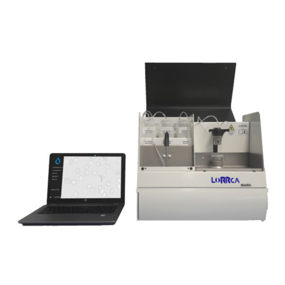
Instrument description Instrument description The Lorrca Maxsis consists of the instrument and a control PC (and optional printer). Main components: 1. Computer and display 2. BOB 3. CUP 4. Projection screen 5. De-ionized water bottle, Waste bottle 6. Pumps 7. Valves 8. - Page 18 Instrument description 9. Osmo HIGH, Osmo LOW, Elon ISO bottles 10. Sample unit 11. Oxygenscan unit (optional) MRN-231-EN Version 5.08 (24-04-2023)
-
Page 19: Technical Specifications
Instrument description 4.1 - Technical specifications Technical specifications for the Lorrca Maxsis: Lorrca® instrument models: Model name Catalogue number Model Lorrca® MaxSis LORC109003 100/240V 50-60Hz Mains voltage Slow blow 220V 1.6 Amp Fuse (20 x 5 mm) Slow blow 110V 3.15 Amp... - Page 20 Instrument description Objective mount C-mount Camera Connection USB 3.0 Minimal resolution 780x582 black/white Dimensions 40x40x40 mm Wave length 655 nm Laser Focus distance 170 mm output power Max 3 mW Tube solution EDTA-Blood Blood sample Deformability test +/- 25 ml Osmoscan +/- 200 ml Oxygenscan...
- Page 21 Instrument description mixer accuracy ±-0.5 mS/cm Reagents 50 - 500 mosm/kg Duration maximum 10 minutes Dilution (with full blood) < 200:1 ± 20% <5% at 3Pa VC elongation measurement MRN-231-EN Version 5.08 (24-04-2023)
-
Page 22: Introduction Lorrca® Maxsis
Instrument description 4.2 - Introduction Lorrca® MaxSis The Lorrca Maxsis is a new version of the earlier released Lorca (Laser-assisted Optical Rotational Cell Analyzer). The Lorrca® MaxSis (Lorrca® hereafter) combines Red Blood Cell (RBC) deformability by ektacytometry, osmoscan and aggregometry; all temperature controlled. It is capable of fully automated measurement and calculation of various phenomena of RBC’s by analysis of their rheological behaviour. -
Page 23: Intended Use
Instrument description 4.2.1 - Intended use The Lorrca Maxsis is intended for the following measurements on human and veterinary blood samples: • Red Blood Cell Deformability ▪ Laser diffraction ektacytometry ▪ Relaxation rate ▪ Parametrization of deformation curve ▪ Cell Stability test ▪... - Page 24 Instrument description Dynamic medium viscosity (mPa*s; 1 Poise = 100 mPa*s). Orientation angle. Shear stress (Pa; 1 Dyne/cm2 = 0.1 Pa). Back-scatter intensity (au = arbitrary units). Intensity parameter resulting from curve fit. Units Arbitrary units. Time, seconds. Shear stress, Pascal (1 Pa = 10 Dynes/cm2). Dynamic viscosity (1 mPa.s = 1 cP (centi-Poise)).
- Page 25 Instrument description Height of syllectogram upstroke (au). Upstroke Back-scatter intensity of syllectogram peak (au). Isc top Back-scatter intensity after one syllectogram half-life (au). Isc ½ Syllectogram base level (au). Isc0 Syllectogram amplitude (au). Area above syllectogram (first 10 s) (au*s). AreaA Area below syllectogram (first 10 s) (au*s).
-
Page 26: General Measurements Description
4.2.4 - General measurements description This section gives a short description of the measurements. 4.2.4.1 - Principle of operation Lorrca Maxsis In order to evaluate the flowing capacity of blood in different parts of the body it is important to have a technique available for the accurate measurement of Red Blood Cell (RBC) properties. - Page 27 Instrument description The LoRRca MaxSis is therefore an indispensable instrument. It uses a Couette geometry with a static BOB and a rotating cylinder (CUP) to create a simple shear flow. Cell deformability A thin layer of red blood cell suspension is sheared between two concentric cylinders.
-
Page 28: Introduction Osmoscan
RBC-shape recovery and aggregation 4.2.4.2 - Introduction Osmoscan The Lorrca Maxsis has an optional equipment with the possibility for automatic measurement of Red Blood Cell (RBC) deformability (expressed as elongation index, EI) as a continuous function of suspending medium osmolality. - Page 29 Instrument description Fig.1 Graphic representation of the measured loss of deformability, the point-of-sickling of SCD RBCs, as a result of oxygen-depletion in time, followed by subsequent gain of deformability of RBC’s during reoxygenation, as is visualized on the Oxygenscan. It is described by pO2: Oxygen- pressure (controlled, in mmHg), and by EI: elongation index (of the RBCs in shear rate), in SC RBCs: Sickle Cell samples Red Blood Cells.
-
Page 30: Safety
Safety Safety Read this paragraph carefully before using the instrument. 5.1 - General safety rules The instrument described in this manual is designed to be used by properly trained personnel only. For the correct and safe use of this instrument it is essential that both operating and servicing personnel follow generally accepted safety procedures in addition to the safety precautions specified in this manual. -
Page 31: Electrical Safety
The waste must be treated as potentially infectious (biohazards) material and disposed of according to local regulations. Check your local environment rules about discharging the waste. • Inside the instrument hazardous voltages reside. Never open the Lorrca Maxsis. Leave servicing to qualified service personnel only. •... -
Page 32: Laser And Mechanical Safety
Safety 5.3 - Laser and mechanical safety • When the hood is open avoid direct eye exposure • The corresponding position of each label on the product indicated: Label on the outside of the instrument • This instrument is equipped with a Class 3R laser. Avoid direct eye exposure. Label inside of the instrument •... -
Page 33: Bio Safety Bob Assembly
Safety "CAUTION – USE OF CONTROLS OR ADJUSTMENTS OR PERFORMANCE OF PROCEDURES OTHER THAN THOSE SPECIFIED HEREIN MAY RESULT IN HAZARDOUS RADIATION EXPOSURE" A Class 3R laser is considered to be safe if handled carefully, with restricted beam viewing. EYE INJURY HAZARD -- DIRECT AND REFLECTED BEAM Do NOT deliberately look into or stare into the beam this can cause injury to the retina. - Page 34 Safety An oxygen meter can be used to detect rapid increasing gas levels in the working space. MRN-231-EN Version 5.08 (24-04-2023)
-
Page 35: Bio Safety Standard Operating Procedures (S.o.p.)
Safety 5.6 - Bio safety Standard Operating Procedures (S.O.P.) In this section the following issues can be found: • Basics of Bio safety • S.O.P. for working with bio hazardous materials If another, more stringent, safety protocol is in place, please adhere to the strictest version. 5.6.1 - Basics of bio safety Basic rules on bio safety in a laboratory;... - Page 36 Safety "Universal Precautions" describes a set of procedures for dealing with subjects based on the assumption that they are positive for blood borne pathogens. Other precautions are necessary to prevent exposure to potential respiratory diseases. 5.6.2.2 - Medical requirements: Routine personal medical assessments are advised at regular intervals (yearly) for all personal exposed to potential biohazard.
- Page 37 Safety stored with personal outer clothing, to avoid transfer of contaminants. Gloves are considered contaminated after being worn. Avoid contamination of work surfaces with gloves. Dispose of gloves into a biohazard container. The use of eye protection is advised while processing samples. Wash hands before leaving the laboratory.
- Page 38 Installation Installation Installation means: Transport, final assembly, fitting the connections and the starting up of the instrument. This should only be performed by trained and skilled personnel. Starting up the instrument and giving instructions for the first (series of) measurements should always be carried out under the supervision of a Service Technician from the manufacturer or their representative.
- Page 39 Installation Laboratory Integrated Dry Nitrogen Gas Supply Specification Laboratory dry N2 purge system wall socket ▪ Flux requirement: gas flow minimal 6 ltr/min, connection optimal 9 ltr/min ▪ Pressure requirement: pressure 0.8- 1.0 bar Stand-Alone Cylinder Dry Nitrogen Gas Supply Required items Specification (example) Pressurized N2 gas cylinder...
- Page 40 Installation AR-CO2 gas pressure reduction valve / flow Alwell type EN ISO 2503 regulator • 1/4" BSP thread connection • Safety Valve • Shut-off valve ▪ Set to 9 ltr/min ▪ Output pressure 0.8 -1 bar RU3 compatible. Follow general requirements with gas connections for installation and use, apply pipe thread compound or gas-rated Teflon tape to the threads on threaded connections before assembling them.
- Page 41 Installation 6.2 - Transport When lifting the packaged instrument, take the following information into account: • The total weight of the instrument is 75 kg (including packaging). • The total weight of the reagent box is depending on the ordered amount. 6.3 - Environmental conditions and setting up the instrument 6.3.1 - Conditions The instrument should be set up on a flat table, level and with sufficient room around it.
- Page 42 5. Connect the Laptop and Printer cables according the laptop and Printer installation instructions. 6. Take the Lorrca Maxsis box out of the packaging in upright position and place it on the floor. 7. Open the box and lift the instrument out of the box by grabbing the handles (H) on the sides (not the hood handle) of the instrument.
- Page 43 Installation 8. Remove the protective materials from the instrument (store them to reuse in case of future transport); ▪ Foam pieces. ▪ Tie-wraps. 9. Move safety plate on pinch valves up 10. Unscrew the bolt from the pump assembly 11. Check/place the correct fuse (F). According ID-plate. Factory default is 230VAC. See section Replace the main fuses 12.
- Page 44 The Instrument is now ready for first start-up. Make sure you are familiar with the use of the Lorrca Maxsis, detailed instructions can be found in the electronic version of the User manual which is installed on the PC, click on the Manual ICON to get access to the manual.
- Page 45 Installation A0021247 USB/Serial converter USB type-A Male on the left side of the laptop b. RS232 Male in the Lorrca QEPC060268 2M SS USB 3.0 A-to-B-Cable-M/M a. USB 3.0 type-A Male on the right side of the laptop b. USB 3.0 type-B Male in the Lorrca QEDK100001 Euro power cable straight IEC C-13 in the Lorrca...
- Page 46 USB type-A Male on the right side of the B male laptop A0021245 USB C to USB-B 2M (optional) Printer connection 6.4 - First Start-up Steady state After switching on, the Lorrca Maxsis needs to warm up. MRN-231-EN Version 5.08 (24-04-2023)
- Page 47 Installation Osmoscan: 5 minutes Oxygenscan: 1 hour (see also pO2 calibration chapter) It is recommended to keep the instrument steady state within series of experiments. Before the instrument can be operated, you have to carry out the following checks and procedures: •...
- Page 48 Installation ▪ Not OK: Misaligned ▪ Check position of the projection screen. Alignment of the projection screen: • Use the hexagon key 2mm to loosen the projection screen holder. • Align the projection screen until the black dot on the screen is aligned with the laser spot.
- Page 49 Installation • Not OK: Driver failure. • Update the camera driver. See Camera driver installation • Choose <LoRRca IO><Rinse cup> and confirm. The tubes are being filled. Dry BOB and CUP. Do not scratch the cup and do not touch the glass with your fingers to prevent staining! Pay attention to the hole in the BOB.
- Page 50 Installation 6.5 - Checking Lorrca Maxsis functionality Both the elongation and aggregation program feature a “check” window that can be used to test the hardware functions individually: ▪ LoRRca status ▪ LoRRca IO ▪ Camera The adjustments made with this checking feature are only temporary and will be restored to default when closing the check window.
- Page 51 Installation 6.5.2 - Lorrca IO Function Description Control to select one of the following laser states: Laser state 1. On, continuous 2. On, Flash (Modulated) 3. Off. Control to select one of the following motor modes: Motor mode 1. Run until in home position, 2.
- Page 52 Installation 6.5.3 - Camera With this test, the laser is turned (continuous) and the motor speed is maintained as set in any of the other tabs. The image shows a colored version of the diffraction pattern (see screen). The “Use colors” check box can be cleared to view the underlying gray scale image.
- Page 53 Installation MRN-231-EN Version 5.08 (24-04-2023)
- Page 54 Lorrca Maxsis Program Lorrca Maxsis Program The Lorrca Maxsis is controlled via an external computer that runs the Lorrca Maxsis program and controlled by mouse pointer. Note: In the next sections move the mouse over the tab and click the left mouse button. Click again on the same tab for detailed information on the subject.
- Page 55 Lorrca Maxsis Program RBC aggregation screen Osmoscan screen Oygenscan screen MRN-231-EN Version 5.08 (24-04-2023)
- Page 56 Lorrca Maxsis Program 7.1 - Main screen MRN-231-EN Version 5.08 (24-04-2023)
- Page 57 Lorrca Maxsis Program 7.2 - Main screen settings 7.2.1 - Screen communication settings Settings: Select the output port for communication. Communication MRN-231-EN Version 5.08 (24-04-2023)
- Page 58 Lorrca Maxsis Program Lorrca Connection with laptop 1. Serial output comport.ASRL1::INSTR. By default 2. Baud rate. Selectable 1200, 4800 ,9600, 38400 and many more default is set on 115200 3. Data bits. Selectable 7 or 8 data bits 4. Parity bit: Selectable none, space, mark, even and odd 5.
- Page 59 Lorrca Maxsis Program Screen appears: Instrument settings Settings parameter Description Range/Setting Alias Alias for internal use Free text Serial number Serial number of the instrument see Typeplate BOB radius (mm) Outer radius of the static bob, in millimeters. [5, 50] mm...
- Page 60 Lorrca Maxsis Program Settings parameter Description Range/Setting CUP radius (mm) Inner radius of the rotating cup, in millimeters. [5, 50] mm Camera As installed, do not change ! cam1 cam2 pO2 Sensor batch number (used File name for calibration information sensor-spot...
- Page 61 Lorrca Maxsis Program 7.3 - Hardware check status (Lorrca status) MRN-231-EN Version 5.08 (24-04-2023)
- Page 62 Lorrca Maxsis Program 7.3.1 - Hardware check IO screen (Lorrca IO) Function Description Control to select one of the following laser states: Laser state 1. On, continuous 2. On, Flash (Modulated) 3. Off. Control to select one of the following motor modes: Motor mode 1.
- Page 63 Lorrca Maxsis Program 7.3.2 - Hardware check Camera screen 7.3.3 - Hardware pO2 Setting/Function Description MRN-231-EN Version 5.08 (24-04-2023)
- Page 64 Lorrca Maxsis Program If the spot is at home position, the oxygen tension (in mmHg), actual Oxygen sensor temperature and actual pressure is visible. In case of errors it will be indicated, see the list of oxygen errors To start the PO2S sensor self check.
- Page 65 Lorrca Maxsis Program 7.4 - Settings screen Before a measurement can be started check if the chosen settings are the appropriate ones, either the default settings or customized settings. You can always revert to the factory default settings by choosing <File ->Load...
- Page 66 Lorrca Maxsis Program Settings Description cannot read extremely large CSV-files. It is therefore advisable to backup and delete this file from the hard disk regularly, before its size exceeds the applicable maximum. <Enumerate file number> With this selection, each measurement is stored in a separate file with a name being equal to the sample id (as entered in the "Insert blood...
- Page 67 Lorrca Maxsis Program Settings parameter Description Range … for at least (s) Time to automatic start [5, 300] s Default = 30 seconds 7.4.3 - Elongation 7.4.3.1 - Deformability curve Parameters Settings parameter Description Logarithmic shear stress axis Checkbox Turns this option on/off 7.4.3.2 - Stress curve determination Parameters...
- Page 68 Lorrca Maxsis Program Settings parameter Description Range Valid determinations per Prescribes the number of subsequent EI determinations (each [2, 1000] shear stress from a newly acquired diffraction image) to find the average EI (and SD) per shear stress. Note: Default setting is "50", for Osmoscan only the setting must be lowered to "5".
- Page 69 Lorrca Maxsis Program 7.4.4.1 - Disaggregation options Settings parameter Description Range Disaggregation shear rate This disaggregation shear rate and time apply throughout [5, 2500] /s (1/s) the aggregation measurement procedure: 1. Before measuring the syllectogram, disaggregation time (s) [0, 3600] s 2.
- Page 70 Lorrca Maxsis Program Settings parameter Description Range Max Error Of Fit (au) It is evaluated whether or not each of the fitting models [0.01, 100] au was successful from the error-of-fit parameter (EOF). Since the syllectogram is sampled uniformly most data points stem from the tail of the curve.
- Page 71 Lorrca Maxsis Program Settings parameter Description Range Binary search steps A binary search algorithm is used to automatically [0, 100] generate two more shear rates to fine-tune the rough procedure (which used shear rates obtained from the user defined "iterate.txt" file). Each binary search step results in two more shear rates to measure the back-scatter intensity.
- Page 72 Lorrca Maxsis Program 7.4.4.3.1 - Edit Iteration shear rates 7.4.4.4 - FSAR options Settings parameter Description Range Perform FSAR procedure Checkbox, to include the FSAR procedure in the aggregation measurement. The FSAR measurement is performed immediately following the iteration procedure.
- Page 73 Lorrca Maxsis Program 7.4.5 - Osmoscan options This is only available when “Enable Osmoscan” is checked. Settings parameter Description Range Enable Osmoscan Checkbox, Turns this option on/off Osmoscan shear stress Default = 30 [10, 50] (Pa) (Pa) Step size (mOsm/kg)
- Page 74 Lorrca Maxsis Program Settings parameter Description Range Logarithmic pO2 axis Checkbox, Default No pO2 scan shear stress (Pa) Default = 30 Pa 0-100 Pa Determine pO2 every (s) Default = 10 s 0-3600 (s) Moving average size Default = 2...
- Page 75 Lorrca Maxsis Program To edit Scan steps: MRN-231-EN Version 5.08 (24-04-2023)
- Page 76 Lorrca Maxsis Program 7.5 - Osmoscan screen This screen appears when starting a scan. See Osmoscan options settings for details on the Settings parameters that influence the measurement. A measurement starts after subsequently clicking <New...(F1)>. On this screen are shown: 1.
- Page 77 Lorrca Maxsis Program 7.5.1 - Osmoscan result screen At measurement completion, the results are displayed on the screen. It is possible to print a measurement report by clicking the <Print report> button. The latest results are automatically saved as a results file (Default name: Results.CSV). See “Settings/Files...
- Page 78 Lorrca Maxsis Program End time Actual time that was valid after the last EI measurement at the given shear stress was performed. Time (s) Time, in seconds, since the beginning of the measurement. Coordinate count Number of coordinates in the iso-intensity curve that describes the shape of the diffraction pattern.
- Page 79 Lorrca Maxsis Program 4. Press <Rinse>. to rinse the system. Screen appears. Empty cup Press <Clean> 5. Remove the empty (rinse) tube from under the needle. 6. Press and the Osmoscan screen appears. 7. Press <F1> or click on to perform another Osmoscan.
- Page 80 Lorrca Maxsis Program MRN-231-EN Version 5.08 (24-04-2023)
- Page 81 Lorrca Maxsis Program 7.6 - Deformability curve determination screen This screen appears when starting a deformability measurement. See Deformability curve for details on the Settings parameters that influence the measurement. A measurement starts after subsequently clicking <New...(F1)>. On this screen are shown: 1.
- Page 82 Lorrca Maxsis Program 7.6.1 - Deformability curve result screen At measurement completion, the results are displayed on the screen. It is possible to print a measurement report by clicking the <Print report> button. The latest results are automatically saved as a results file (Default name: Results.CSV). See “Settings/Files...
- Page 83 Lorrca Maxsis Program Coordinate count or Number of coordinates in the iso-intensity curve that describes the shape of the Crd cnt diffraction pattern. A (pixels) Vertical axis of ellipse. B (pixels) Horizontal axis of ellipse. Elongation index. Eof (pixels) Error of fit. This parameter represents the average distance (in pixel units) of the iso-intensity pixels to the best-fit ellipse that resulted.
- Page 84 Lorrca Maxsis Program 7.7 - Oxygenscan screen This screen appears when starting a scan. See Oxyscan options settings for details on the Settings parameters that influence the measurement. A measurement starts after subsequently clicking <New...(F1)>. On this screen are shown: 1.
- Page 85 Lorrca Maxsis Program 7.7.1 - Oxygenscan result screen At measurement completion, the results are displayed on the screen. It is possible to print a measurement report by clicking the <Print report> button. The latest results are automatically saved in result files (in original format in folder: Results.CSV and in an alternative format in a sub folder named "Data format 2022").
- Page 86 Lorrca Maxsis Program B (pixels) Horizontal axis of ellipse. Elongation index p02 (mm/Hg) The oxygen pressure measured in the sample while deoxygenating N2 (valve) Position of the N2 valve; 0 or 1, indicating On or Off. The N2 flow may also be controlled.
- Page 87 Lorrca Maxsis Program 1. Colored diffraction pattern. 2. Curve display screen. 3. Indication of cell shape. 4. Measurement and sample details. 5. Measurement results. 7.8.1 - Stability curve determination results screen At measurement completion, the results are displayed on the screen.
- Page 88 It reflects how well the iso-intensity coordinates comply with the ellipse model. 7.8.1.2 - Open Stability curve files A .SMP or .CSV result file can be shown again. Default folder C://LoRRca MaxSis/Results/Elongation. MRN-231-EN Version 5.08 (24-04-2023)
- Page 89 Lorrca Maxsis Program 7.9 - Cell Membrane stability screen This screen appears when starting a stability test. See Stability test Settings for details on the Settings parameters that influence the measurement. The cell membrane stability test consists of 3 stages.
- Page 90 Lorrca Maxsis Program 7.9.1 - Deformability results 1 screen At measurement completion, the results are displayed on the screen. It is possible to print a measurement report by clicking the <Print report> button. The latest results are automatically saved as a results file (Default name: Results.CSV). See “Settings/Files...
- Page 91 Lorrca Maxsis Program After a measurement has completed, the program sets the fill/empty speed (<Settings> <General options Fill/ (rps)>) and asks the operator to remove the blood sample. empty speed • Press <Clean>. Sample is removed and system is rinsed. Sample is lost and no longer available.
- Page 92 Lorrca Maxsis Program 7.9.4 - Cell membrane stability results screen At measurement completion, the results are displayed on the screen. It is possible to print a measurement report by clicking the <Print report> button. The latest results are automatically saved as a results file (Default name: Results.CSV). See “Settings/Files...
- Page 93 Lorrca Maxsis Program 7.9.5 - Deformability results 2 screen At measurement completion, the results are displayed on the screen. It is possible to print a measurement report by clicking the <Print report> button. The latest results are automatically saved as a results file (Default name: Results.CSV). See “Settings/Files...
- Page 94 Lorrca Maxsis Program Shear stress (Pa) Applied shear stress. Coordinate count or Number of coordinates in the iso-intensity curve that describes the shape of the Crd cnt diffraction pattern. A (pixels) Vertical axis of ellipse. B (pixels) Horizontal axis of ellipse.
- Page 95 Lorrca Maxsis Program A (pixels) Vertical axis of ellipse. B (pixels) Horizontal axis of ellipse. Elongation index Eof (pixels) Error of fit. This parameter represents the average distance (in pixel units) of the iso-intensity pixels to the best-fit ellipse that resulted. It reflects how well the iso-intensity coordinates comply with the ellipse model.
- Page 96 Lorrca Maxsis Program #Valid The number of diffraction patterns that were within the ±2SD confidence interval. This number agrees with the desired count as given in the Settings menu (<Settings<Determinations per shear stress). 7.10 - RBC aggregation screen This screen appears when starting RBC aggregation test. See...
- Page 97 Lorrca Maxsis Program 7.10.1 - RBC aggregation result screen At measurement completion, the results are displayed on the screen. It is possible to print a measurement report by clicking the <Print report> button. The latest results are automatically saved as a results file (Default name: Results.CSV). See “Settings/Files...
- Page 98 Lorrca Maxsis Program Result parameter Description Upstroke Change in back-scatter intensity due to RBC relaxation. Isctop – Isc dis Isc top Maximum back-scatter intensity recorded throughout the syllectogram => Peak intensity (usually the top of the syllectogram). Isc½ Back-scatter intensity at t ½...
- Page 99 Lorrca Maxsis Program Result parameter Description RBC-shape recovery contribution (r = recovery). RBC-shape recovery time constant. RBC-rouleaux formation contribution (f = fast). RBC-rouleaux formation time constant. RBC-3D aggregate formation contribution (s = slow). RBC-3D aggregate formation time constant. Syllectogram base level.
- Page 100 Lorrca Maxsis Program 7.10.1.2 - Open Aggregation files A .SMP or .CSV result file can be shown again. Default folder C://LoRRca MaxSis/Results/Aggregation. 7.10.1.3 - Rinse cup RBC Aggregation After a measurement has completed, the program sets the fill/empty speed (<Settings>...
- Page 101 • Start Lorrca software. Steady state After switching on, the Lorrca MaxSis needs 5 minutes to warm up. For pO2 scan: The Lorrca Maxsis needs at least 60 minutes to warm up. Recommended is to perform the "Self-check&calibration" weekly. It is noted with a pop-up if performed more than a week ago.
- Page 102 General operation procedure 8.2 - Preparations First preparations: 1. Check the de-ionized water bottle, should be filled 2. Check the waste bottle, should be empty 3. Place the reagent bottles (if applicable) 4. Check applicable viscosity of reagents 5. Check the gradient pump tubes by pushing cassettes downwards (no click if correctly fixed and in parallel position) 6.
- Page 103 General operation procedure For Instruments without Oxygenscan and without Luer connection on top of the bob: 1. Prepare 5 ml vial of Elon ISO or Oxy ISO 2. Select from the menu Deformability Curve 3. Draw 1 ml Elon or Oxy ISO from the vial with a pipette or pastette and insert this into the cup 4.
- Page 104 After opening, the reagents can be used for one month, if stored at 4-7°C (this holds for storage in instrument bottles as well as in the storage bottle). • Only use the reagent bottles as supplied with the Lorrca Maxsis. 8.2.2 - RBC necessary per test/scan •...
- Page 105 General operation procedure 8.2.3 - Estimated number of RBC in the laser path The suspension volume in the laser beam = 0,3 microliter (1mm2 x 0.3 mm gap) deformability curve and Osmoscan there are 100 * 10 For a RBC in 5000 microliter reagent which results in 6000 RBC (100 * 10 /5000 *0,3).
- Page 106 General operation procedure 1. Check that all tubes are connected correctly to the Osmo HIGH and Osmo LOW, water and waste bottles 2. Select "Osmoscan" on main screen. The Osmoscan screen appears 3. Place a sample tube with DI water at the needle position. 4.
- Page 107 General operation procedure • Lower the BOB if applicable. • Start a new measurement by clicking the <New…(F1)> button in the screen. • Enter the measurement ID. The measurement ID should not contain other characters than digits or letters. It is used to store measurement data.
- Page 108 General operation procedure 1. Place the sample at sampling position. 2. Close the hood 3. Press <OK> 8.3.3 - Adjust video camera Osmoscan screen MRN-231-EN Version 5.08 (24-04-2023)
- Page 109 General operation procedure It displays a colored version of the diffraction pattern. Because there are air bubbles in the cup this pattern it will be very irregular: • It is optional to adjust the camera gain (bar on the right side). If the sample volume was set based on the cell count, this is normally not required.
- Page 110 General operation procedure 8.3.5 - Start new measurement After a measurement has completed and the report is printed (yes/no) • Press the <Yes> for printed report. • Press the <No> if no printed report is required. Screen appears: Rinse gradient system 1.
- Page 111 General operation procedure 4. Press <Rinse>. to rinse the system. Screen appears. Empty cup Press <Clean> 5. Remove the empty (rinse) tube from under the needle. 6. Press and the Osmoscan screen appears. 7. Press <F1> or click on to perform another Osmoscan. New...F1 it is not necessary to dry the bob and cup between Osmoscan runs.
- Page 112 General operation procedure 8.4 - Performing Deformability curve test Start software 8.4.1 - Preparing a blood sample Use the dedicated Lorrca reagents (see Appendix - Parts list) A blood sample can be stored at a maximum of one hour (at room temperature). After that the sample cannot be used anymore.
- Page 113 General operation procedure 4. Gently mix the blood by immediately inverting the tube 40 times (don’t shake) until it is homogeneous. 5. Click on on the Main screen. Deformability curve 6. Press <New...(F1)> MRN-231-EN Version 5.08 (24-04-2023)
- Page 114 General operation procedure 8.4.2 - Insert blood sample deformability curve screen Before inserting blood: Prepare a blood sample for RBC test. • Lower the BOB if applicable. • Start a new measurement by clicking the <New…(F1)> button in the screen. •...
- Page 115 General operation procedure Depending on the instrument there are two ways that the sample suspension may be inserted. • For all instruments by pipetting 880 µl directly into the bottom of the cup, followed by slowly lowering the bob. • If there is a bracket with a Luer connection on the bob.
- Page 116 General operation procedure 8.4.3 - Adjust video camera deformability screen • It is optional to adjust the camera gain (bar on the right side). If the sample volume was set based on the cell count, this is normally not required. Default gain of 300 will be valid for most samples if the volume is based on the cell count.
- Page 117 General operation procedure 8.4.4 - Deformability curve result screen At measurement completion, the results are displayed on the screen. It is possible to print a measurement report by clicking the <Print report> button. The latest results are automatically saved as a results file (Default name: Results.CSV). See “Settings/Files ”...
- Page 118 General operation procedure 1. Press <Clean> 2. Open the hood. 3. Dry the cup and bob with a tissue and for instruments equipped with a bracket with a Luer connection, also blow the bob and cup dry the insertion tube with a 60 ml Syringe. 4.
- Page 119 General operation procedure 1. Bring the blood sample to room temperature. 2. For the highest precision perform a cell count and see chapter RBC necessary per test/scan for the required whole blood volume. 3. Just before the measurement, mix the calculated sample volume (as a reference 25 μl of normal EDTA- anticoagulated blood) in the 5 ml ready to use Elon ISO.
- Page 120 General operation procedure • Lower the BOB if applicable. • Start a new measurement by clicking the <New…(F1)> button in the screen. • Enter the measurement ID. The measurement ID should not contain other characters than digits or letters. It is used to store measurement data.
- Page 121 General operation procedure 8.5.3 - Adjust video camera stability screen • It is optional to adjust the camera gain (bar on the right side). If the sample volume was set based on the cell count, this is normally not required. Default gain of 300 will be valid for most samples if the volume is based on the cell count.
- Page 122 General operation procedure 8.5.4 - Stability curve determination results screen At measurement completion, the results are displayed on the screen. It is possible to print a measurement report by clicking the <Print report> button. The latest results are automatically saved as a results file (Default name: Results.CSV). See “Settings/Files ”...
-
Page 123: Preparing A Blood Sample
General operation procedure 1. Press <Clean> 2. Open the hood. 3. Dry the cup and bob with a tissue and for instruments equipped with a bracket with a Luer connection, also blow the bob and cup dry the insertion tube with a 60 ml Syringe. 4. -
Page 124: Insert Blood Sample Membrane Screen
General operation procedure 1. Bring the blood sample to room temperature. 2. For the highest precision perform a cell count and see chapter RBC necessary per test/scan for the required whole blood volume. 3. Just before the measurement, mix the calculated sample volume (as a reference 25 μl of normal EDTA- anticoagulated blood) in the 5 ml ready to use Elon ISO. - Page 125 General operation procedure • Lower the BOB if applicable. • Start a new measurement by clicking the <New…(F1)> button in the screen. • Enter the measurement ID. The measurement ID should not contain other characters than digits or letters. It is used to store measurement data.
-
Page 126: Adjust Video Camera Membrane Screen
General operation procedure 8.6.3 - Adjust video camera membrane screen • It is optional to adjust the camera gain (bar on the right side). If the sample volume was set based on the cell count, this is normally not required. Default gain of 300 will be valid for most samples if the volume is based on the cell count. -
Page 127: Cell Membrane Stability Results Screen
General operation procedure 8.6.4 - Cell membrane stability results screen At measurement completion, the results are displayed on the screen. It is possible to print a measurement report by clicking the <Print report> button. The latest results are automatically saved as a results file (Default name: Results.CSV). See “Settings/Files ”... -
Page 128: Deformability Results 2 Screen
General operation procedure 8.6.5 - Deformability results 2 screen At measurement completion, the results are displayed on the screen. It is possible to print a measurement report by clicking the <Print report> button. The latest results are automatically saved as a results file (Default name: Results.CSV). See “Settings/Files ”... -
Page 129: Performing Rbc Aggregation Test
General operation procedure 1. Press <Clean> 2. Open the hood. 3. Dry the cup and bob with a tissue and for instruments equipped with a bracket with a Luer connection, also blow the bob and cup dry the insertion tube with a 60 ml Syringe. 4. -
Page 130: Insert Blood Sample Rbc Aggregation Screen
General operation procedure 1. Incubate 4 ml of whole blood, with at least 40 ml of air (1:10), in a tube preferably on a roller-bank for 15 minutes, minimum. About 600-900 µl of whole blood is required to perform an aggregation measurement. - Page 131 General operation procedure The measurement ID is not allowed to contain characters other than digits or letters. It is used to store measurement data (if enabled in the Settings menu). The “Remarks” and “Donation time” fields may be ignored but serve to include sample details. Always check whether CUP and BOB are clean and dry before entering a blood sample.
-
Page 132: Adjust Temperature Rbc Aggregation Screen
General operation procedure 8.7.3 - Adjust temperature RBC aggregation screen It subsequently displays a “Wait until temperature is stable” window. • Press <Start now> if you want to start the measurement immediately. The measurement starts and the curve starts to appear. MRN-231-EN Version 5.08 (24-04-2023) -
Page 133: Rbc Aggregation Result Screen
General operation procedure 8.7.4 - RBC aggregation result screen At measurement completion, the results are displayed on the screen. It is possible to print a measurement report by clicking the <Print report> button. The latest results are automatically saved as a results file (Default name: Results.CSV). See “Settings/Files ”... - Page 134 General operation procedure 1. Press <Clean> 2. Open the hood. 3. Dry the cup and bob with a tissue and for instruments equipped with a bracket with a Luer connection, also blow the bob and cup dry the insertion tube with a 60 ml Syringe. 4.
-
Page 135: Performing Oxygenscan
General operation procedure 8.8 - Performing Oxygenscan This manufacturer’s standard operating protocol is to be validated by each lab. Prior to use • The sample should not be stored at room temperature for more than 4 hours. • Samples should be stored at 4-7 ⁰C for a minimum of 30 minutes. •... - Page 136 5. The self-check takes around 10 minutes. If the Self Check fails: the pO2 scan will be greyed out in the main menu (screenshot) All calibration results are stored in C:Lorrca MaxSis\SelfCheck_V01.txt Steps of the Self-check are: Display sensor batch number: 200123-001 (example) - Step 1: Temperature check: OK (37,0⁰C )
-
Page 137: Cleaning Procedure
General operation procedure (In Hardware check screen, Lorrca IO, set Cup velocity to 1 rps and motor mode to run home) Damaged; verify that the sensor spot is not damaged by rubbing off the black silicone backing. Expired; the sensor spot may have expired, try a new sensor spot to see whether this one passes the test. -
Page 138: Place Sample Oxygenscan Test
General operation procedure 6. Return the sample to the fridge. 7. Gently mix the Oxy ISO vial by reversing 40x, use the sample/Oxy ISO solution within 15 minutes. (Oxy ISO is not a storage medium) 8. Slowly draw 1,6 mL of the sample/Oxy ISO solution in a new(dry) 3 mL syringe. Remove air bubbles. A blood sample can be kept at room temperature during a limited time. - Page 139 General operation procedure Both pictures above show sharp edges, the aspiration procedure was correct. Check the leveling around the Oxygensensor spot when the cup is rotated to the left and when rotated forward. Picture above shows correct leveling. MRN-231-EN Version 5.08 (24-04-2023)
-
Page 140: Oxygenscan
General operation procedure Picture above indicating incorrect leveling. If leveling is not correct, thoroughly clean Bob and Cup with X-Clean and rub with X-Clean wetted tissue. Rinse well with DI water and rub with DI water tissue. 8. Close the hood 9. -
Page 141: End Of Day Wash And Powering Off
General operation procedure At measurement completion, result-data is displayed on-screen, the software offers an option to print (yes/ no), and the data is stored on the drive of the computer. Always correlate measurement results with the graph before reporting. After each Oxygenscan follow the Cleaning procedure After the last Oxygenscan of the day, close the nitrogen gas supply on the bottle to avoid unnecessary loss of gas by a possible small leak. - Page 142 General operation procedure 1. Remove both tubes on the reagent bottles. 2. Mount the reagent tubes to the cleaning tube LORC070905 from the cleaning solution bottle. 3. Place a tube with cleaning solution at at the Osmoscan sample position. 4. Close the Lorrca program window. 5.
-
Page 143: Decontamination Procedures Routine
General operation procedure 1. Restart the Lorrca program on the computer 2. If applicable: skip the Sensor calibration procedure 3. Place a tube with DI water at the Osmoscan sample position. 4. Remove the tube from the cleaning solution and place it on the DI water bottle 5. -
Page 144: Waste Container Disposal
General operation procedure Small spills of biohazard material should be treated by first covering them with an absorbent paper to avoid the formation of aerosols. Disinfect the spill by slowly pouring on a disinfecting solution working from the outside to the centre of the spill in a circular motion. Leave the spill long enough for disinfection to take place (check decontaminating instructions on the disinfectant container for time) and then carefully wipe up, use protection gloves. - Page 145 General operation procedure • Go to Hardware check ->Lorrca • Press <Rinse cup>. • Press <Rinse gradient pump>. (If available) • Dry CUP and BOB. Do not scratch the CUP! • End of day wash (see further in this chapter) •...
-
Page 146: Reporting
Reporting Reporting Reporting examples. MRN-231-EN Version 5.08 (24-04-2023) -
Page 147: Deformability Report
Reporting 9.1 - Deformability Report Deformability curve determination parameters explanation MRN-231-EN Version 5.08 (24-04-2023) -
Page 148: Cell Membrane Stability Report
Reporting 9.2 - Cell Membrane Stability report page 1 of 3 Deformability results 1 parameters explanation MRN-231-EN Version 5.08 (24-04-2023) -
Page 149: Cell Membrane Stability Report
Reporting 9.3 - Cell Membrane Stability report page 2 of 3 Stability results parameters explanation MRN-231-EN Version 5.08 (24-04-2023) -
Page 150: Cell Membrane Stability Report
Reporting 9.4 - Cell Membrane Stability report page 3 of 3 Deformability results 2 parameters explanation MRN-231-EN Version 5.08 (24-04-2023) -
Page 151: Osmoscan Report
Reporting 9.5 - Osmoscan Report Osmoscan parameters explanation MRN-231-EN Version 5.08 (24-04-2023) -
Page 152: Oxygen Report (.Csv)
Reporting 9.6 - Oxygen Report (.CSV) Measurement result file (standard) MRN-231-EN Version 5.08 (24-04-2023) - Page 153 Reporting Measurement result format (Data format 2022) MRN-231-EN Version 5.08 (24-04-2023)
-
Page 154: Troubleshooting
This paragraph is intended for trained personal. They should be familiar with at least the operation and various basic settings. Do not hesitate to contact RR Mechatronics if you are confronted by a fault which is not described in this paragraph. - Page 155 • Switch on the LoRRca and start the software. Note: For Error codes > 25: Restart the LoRRca MaxSis, if still NOT OK: Call RR Mechatronics see Service request protocol MRN-231-EN Version 5.08 (24-04-2023)
-
Page 156: Error Messages (Oxygenscan)
Troubleshooting 10.2 - Error Messages (Oxygenscan) Message Description Solution No PT100 connected! No PT100 connected to the device or Check the PT100 presence and its PT100 not correctly connected. soldered connection to the PCB. No sensor connected! No sensor is connected (Amplitude < Check the optical coupling to the 1000). -
Page 157: Troubleshooting Table
Troubleshooting SD card full! SD card is full. Backup and wipe SD card Pulse counter overflow! The pulse counter has reached the Device has to be sent to RRM for pulse counter overflow limit. service Temperature sensor not available! The temperature sensor was activated Device has to be sent to RRM for but it is not present on this device. -
Page 158: Communication Problems
Troubleshooting Field Description Check/Remedy • Check connection cable. Reconnect if necessary. Camera No camera image • Check Camera driver is not defect. • Check position projection screen Camera Disturbed image • Adjust projection screen if necessary (see Adjusting projection screen •... - Page 159 Troubleshooting For Osmoscan only at Lorrca Connection: The option "Oxygenscan" has to be disabled in "Setting screen " 1. Connect the Lorrca instrument 2. Set comport for the instrument at Lorrca Connections, the comport number is given by Windows. For Oxygen scan: The option "Oxygenscan"...
- Page 160 Troubleshooting Also Windows settings concerning USB-ports can be set not correctly, check USB Settings, especially when using the USB-hub. At Windows power management: USB selective suspend setting: both disabled At Device manager: USB Controllers: UNCHECK: Allow the computer to turn off this device to save power MRN-231-EN Version 5.08 (24-04-2023)
- Page 161 Weekly Monthly Yearly Clean Reagent handling Visual check Pump tube replacement Periodical maintenance* Report irregularities in the logbook. *The yearly maintenance has to be performed by a trained engineer. Please contact RR Mechatronics for more information. MRN-231-EN Version 5.08 (24-04-2023)
- Page 162 Maintenance 11.2 - Cleaning Clean the Instrument once a day. Note the following points: Never use compressed air for cleaning, as this may cause swarf and fragments to be blown into the instrument. The use of flammable fluids is not allowed. Do not use medical alcohol, bleach or any solvent for cleaning, use only DI water or Starrsed X-clean.
- Page 163 This file must be placed in the main directory C:/Lorrca MaxSis/. The old data file should be moved to a separate directory where the old data files of the used spots are stored (this might be useful in the future) MRN-231-EN Version 5.08 (24-04-2023)
- Page 164 Maintenance 4. Start software and select on tab Settings, screen appears: Hardware settings Lorrca Instrument settings 5. Select at PO2 Sensor batch number the correct calibration file, which is given with the sensor-spot. If the new calibration file cannot be found after replacement of the sensor-spot, the following warning is given Press OK 6.
- Page 165 11.5 - Visual checks Report irregularities in the logbook. • Check for scratches on surface projection screen or CUP: ▪ No scratches: Continue ▪ Scratches: Contact RR Mechatronics • Check tube attachments. ▪ When loose: re-attach ▪ When damaged: replace 11.6 - Lorrca reagents routine...
- Page 166 Place the memory stick in the USB slot of the computer (or the USB extension cable). • Drag the file C:\LoRRca Maxsis\Results onto the memory stick. If you have a previously stored backup files on the memory stick, you should rename it first.
- Page 167 Maintenance 11.11 - Adjustments and replacements Replacement parts list can be found in Appendix - Parts list 11.11.1 - Adjusting projection screen • Switch the instrument. • Start-up the PC. • Choose LoRRca software program. • Select <Hardware check>. • Move the Bob down.
- Page 168 Maintenance ▪ Not OK: Misaligned ▪ Check position of the projection screen. Alignment of the projection screen: • Use the hexagon key 2mm to loosen the projection screen holder. • Align the projection screen until the black dot on the screen is aligned with the laser spot.
- Page 169 Maintenance • Not OK: Driver failure. • Update the camera driver. See Camera driver installation • Choose <LoRRca IO><Rinse cup> and confirm. The tubes are being filled. Dry BOB and CUP. Do not scratch the cup and do not touch the glass with your fingers to prevent staining! Pay attention to the hole in the BOB.
- Page 170 (3,2mm tube) and the rinse pump uses QWLV090012 (1,6mm tube) Always replace the correct tube! The pumps are in the foot of the Lorrca Maxsis, pull on the lid to open the pump drawer. The pump tube needs to be replaced every 6 months.
- Page 171 Maintenance • Remove the old tube from the pump as shown: • Pull the tube from the connectors and install the new tube in the reverse order. • Check that all connecting tubes and the tube cover are attached. 11.11.3.2 - Pump connection tubing Pumps to Needle assembly (LORC070904) Note: Start to install with the tube end with label 6 which is shown GREEN...
- Page 172 Maintenance 3. Connect tube with label 7 to the output port of the 4. Connect tube with label 4 to the Input port of the Waste pump. Waste pump. Tube to needle assembly (LORC070901) • Connect tube with label 5 onto connector 5 •...
- Page 173 Maintenance • Connect tube with label 2 onto connector 2 11.11.4 - Tubing replacements Tubing as used for Osmoscan 11.11.4.1 - Gradient pump tube replacement After 500 measurements/ half year. MRN-231-EN Version 5.08 (24-04-2023)
- Page 174 Maintenance Disconnect water and reagent tubing and pull up the sample needle Lower the BOB and perform two times a function Prime all [ LoRRca IO ] [ Prime all ] [ Start ] Hardware check Open the pump drawer and pull the drawer out. MRN-231-EN Version 5.08 (24-04-2023)
- Page 175 Maintenance Replace the tube assembly with new tube assembly Release the tube cassette. following Install LORC070901 tubing (see also Appendix - Parts list spare- and replacement parts) 11.11.4.2 - Install LORC070901 tubing Put the waste tubing labeled with 3 and 5 into the first tube bracket Assure that the tubing is not twisted and the locking ridge is pointing up Continue the with the four other tube brackets MRN-231-EN Version 5.08 (24-04-2023)
- Page 176 Maintenance Continue the with the rest of the tube brackets • Hook the first tube bracket onto the pump frame. (Waste bracket) This how it looks when all the tube brackets are in place. Tube to needle assembly Connect tube with label 3 onto connector 3 •...
- Page 177 Maintenance • Connect small (sample) tube onto the first • Connect tube with label 2 onto connector 2 cassette. MRN-231-EN Version 5.08 (24-04-2023)
- Page 178 Maintenance MRN-231-EN Version 5.08 (24-04-2023)
- Page 179 Maintenance 11.11.4.3 - Install LORC070902 tubing set 1 Note: Start to install with the tube end with label 2 which is shown GREEN in the picture. Next picture: The installed tube is now BLUE, continue with the next GREEN tube. 1.
- Page 180 Maintenance 7. Connect the tube "1" onto connector 1. Tube to needle assembly 1. Connect tube with label 3 on the connector 3 2. Connect the other end to the needle assembly MRN-231-EN Version 5.08 (24-04-2023)
- Page 181 Maintenance MRN-231-EN Version 5.08 (24-04-2023)
- Page 182 Maintenance 11.11.4.4 - Install LORC070903 tubing set 2 Note: Start to install with the tube end with label 5 which is shown GREEN in the picture. Next picture: The installed blue tube is now BLUE, continue with the next GREEN tube. Start with tube end with label 5.
- Page 183 Maintenance 8. Take the long end of the tube and run this through 9. Connect tube "4" on the bob, connect tube "6" on the the front hole EC-sensor Tubing to waste connector • Connect tube labelled with waste to the waste •...
- Page 184 Maintenance MRN-231-EN Version 5.08 (24-04-2023)
- Page 185 Maintenance 11.11.4.5 - Install LORC070904 tubing set 3 Note: Start to install with the tube end with label 6 which is shown GREEN in the picture. Next picture: The installed tube is now BLUE continues with the next GREEN tube. 1.
- Page 186 Maintenance [ LoRRca IO ] [ Prime all ] [ Start ] Hardware check • Check the pump function and exclude leakage, check the tubes are filled correctly without air bubbles. 11.11.5 - Preparation for long time inactivity In case of long-time inactivity or temporary storage: 1.
- Page 187 Appendix for Lorrca Appendix for Lorrca Appendix section MRN-231-EN Version 5.08 (24-04-2023)
- Page 188 1, June 2018 Version: RR Mechatronics shall not in any event be liable for any direct, indirect, special, incidental, or consequential damages, including, without limitation, lost revenues, or lost profits, arising out of or in any way connected with the use or misuse of the information or lack of information in this Instruction.
- Page 190 This picture is from a Lorrca without a cup. Please do not remove the cup! Part 2a: (applicable for Lorrca 109001) Use another piece of foam and cut two blocks in the following size with a cut in the side to put it over the pump plate.
- Page 191 Part 2b: (applicable for Lorrca109003) Use safety plate (yellow/green in the picture) to secure the pinch valves Tighten the bolt on the pump assembly to secure the peristaltic pumps.
- Page 192 Appendix for Lorrca 12.2 - Appendix - Spare parts In your order, first state the part number followed by the quantity required. Since 01-01-2020 new ordering numbers are used by RR Mechtronics for all spare parts and consumables. The new ordering numbers are the part numbers, preceded with an "S"...
- Page 193 QRR 010946 Starrsed X-Clean 5 Ltr Accessories Part No Description LORC110100 Manual Lorrca MaxSis QEDK100017 Euro plug lead 10A with locking system for IEC inlets QWBM540005 Hex key 2 mm A0021247 RS232 Adapter cable (serial converter) MRN-231-EN Version 5.08 (24-04-2023)
- Page 194 Appendix for Lorrca 12.3 - Appendix - Parts list Order number Periodical Maintenance Kit SLORC110985 Contents: Part No Description LORC070901* Tubing set Peristaltic pump QWLV090011 Peristaltic pump tube 3,2mm (waste pump) QWLV090012 Peristaltic pump tube 1,6mm (rinse pump) LORC070902* Tubing set 1 LORC070903* Tubing set 2 LORC070904*...
- Page 195 Appendix for Lorrca LORC080902 Bob pcb assembly LORC080917 Heater assembly LORC120408 Bob cylinder including capillary (for <2021 models) LORC040910 EC Cell assembly LORC060910 Camera assembly (for USB 3.0) LORC020903 Servo motor assembly PO2S020153 PO2S luminophore spots PO2S200166 Reducer (for <2021 models) LORC120903 Motor retro kit (for <2021 models) QEDV130017...
- Page 196 Drawings and parts Lorrca Drawings and parts Lorrca Drawing section. MRN-231-EN Version 5.08 (24-04-2023)
- Page 197 Drawings and parts Lorrca 13.1 - LORC070020 Tubing diagram Parts LORC070020 Tubing diagram MRN-231-EN Version 5.08 (24-04-2023)
- Page 198 Drawings and parts Lorrca 13.2 - LORC080020 Connection diagram MRN-231-EN Version 5.08 (24-04-2023)
- Page 199 Log book (Example) Log book (Example) Name: Date: Description visual inspection NOT OK REMARKS Scratches on glass surface of cup Check tube attachments Check tube damage Description functional test NOT OK REMARKS Hardware check For accordance Manager: Remarks: MRN-231-EN Version 5.08 (24-04-2023)
- Page 200 Log book (Example) MRN-231-EN Version 5.08 (24-04-2023)
- Page 201 Glossary of Terms AMC stands for the Academic Medical Center in Amsterdam, Netherlands. EI = expressed as elongation index HE stands for Hereditary Elliptocytosis. Lorca Lorca stands for Laser-assisted Optical Rotational Deformability Cell Analyzer MWM stands for Medical Waste Management RBC is used as a short for Red Blood Cell...
- Page 202 ....Cell membrane stability results screen..92, Features of the Lorrca Maxsis ....Cell Membrane stability screen.
- Page 203 Lorrca Maxsis Program....Lorrca reagents......
- Page 204 Preparation for long time inactivity... Troubleshooting table....Preparations......Tubing replacements.
Need help?
Do you have a question about the Lorrca MaxSis and is the answer not in the manual?
Questions and answers