
Related Manuals for Edwards HV8000 aftercooler Mk4


Summary of Contents for Edwards HV8000 aftercooler Mk4
- Page 1 edwardsvacuum.com HV8000 Aftercooler (Mk4) INSTRUCTION MANUAL A71213880_A Original instructions...
- Page 2 Copyright notice ©Edwards Limited 2020. All rights reserved. Trademark credit Edwards and the Edwards logo are trademarks of Edwards Limited, Innovation Drive, Burgess Hill, West Sussex RH15 9TW. Disclaimer The content of this manual may change from time to time without notice. We accept no liability for any errors that may appear in this manual nor do we make any expressed or implied warranties regarding the content.
-
Page 3: Table Of Contents
Contents 1. Safety and compliance........5 1.1 Definition of Warnings and Cautions. - Page 4 List of Figures Figure 1: Aftercooler components..........8 Figure 2: Aftercooler dimensions.
-
Page 5: Safety And Compliance
A71213880_A - Safety and compliance 1. Safety and compliance 1.1 Definition of Warnings and Cautions NOTICE: For safe operation from the start, read these instructions carefully before you install or commission the equipment. Read all the safety instructions in this section and the rest of this manual carefully and make sure that you obey these instructions. -
Page 6: Safety Symbols
A71213880_A - Safety and compliance 1.2 Safety symbols The safety symbols on the products shows the areas where care and attention is necessary. The safety symbols that follow are used on the product or in the product documentation. Warning/Caution An appropriate safety instruction must be followed or caution to a po- tential hazard exists. -
Page 7: Introduction
A71213880_A - Introduction 2. Introduction 2.1 Scope This manual provides installation, operation and maintenance instructions for the HV8000 aftercooler (Mk4) - referred to as aftercooler in this manual. Use the aftercooler as described in this manual. Use this manual together with the HV8000 manual (Publication number A31103880). -
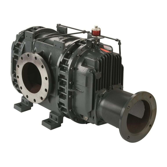
Page 8: Figure 1 Aftercooler Components
A71213880_A - Introduction Figure 1 Aftercooler components 1. Water inlet connection 1. Water inlet connection 2. Heat sink 2. Heat sink 3. Cooling block 3. Cooling block 4. Mounting/support flange 4. Mounting/support flange 5. Water outlet connection 5. Water outlet connection 6. -
Page 9: Aftercooler Kit Components
A71213880_A - Introduction 2.3 Aftercooler kit components Refer to Figure: Aftercooler components for the aftercooler components. A flow restrictor (A24802232) is supplied separately with the aftercooler kit. Table 1 Retrofit kit (A71213024) components Description Quantity Check Mk4 aftercooler Gasket M20 x 145 stud bolt M20 nut M20 plain washer M20 S-coil washer... -
Page 10: Technical Data
A71213880_A - Technical data 3. Technical data Table 3 Technical data Parameter Value Mass (including flange) 25 kg (approximate) 8 – 10 l/m Flow rate (2.1 – 2.6 US gallon/minute) Cooling water operating tempera- +5 °C ‑ +35 °C ture range Maximum working pressure 5 barg (7.25 psig) Mounting/support flange... -
Page 11: Installation
A71213880_A - Installation 4. Installation 4.1 Installation safety WARNING: BLOCKED COOLING WATER SUPPLY Risk of damage to equipment. If the cooling waterlines are closed or blocked when the aftercooler is in operation, there will be high pressure and temperature inside the aftercooler. -
Page 12: Install The Aftercooler
A71213880_A - Installation If the equipment is not to be used immediately, refit the protective packaging and store in suitable conditions as described in Storage on page 20. 4.3 Install the aftercooler Note: The aftercooler will physically fit to either flange (port) of the HV8000, but you must install it at the discharge (outlet) side of the pump. -
Page 13: Removal Of Existing Aftercooler
A71213880_A - Installation 4.3.1 Removal of existing aftercooler CAUTION: WATER SPILL Risk of damage to equipment. The aftercooler being replaced may contain water after it is removed from the pump. Make sure that no water enters the booster pump system. CAUTION: HEAVY OBJECT Risk of injury. -
Page 14: Figure 5 Cooling Water Connection
A71213880_A - Installation The aftercooler requires two gaskets, one below and one above the flange. You must replace both the gaskets. To tighten the aftercooler, you must tighten the opposite bolts one by one. Cooling water supply connections The cooling water inlet connection is on the opposite side to the temperature sensor connection. -
Page 15: Steel Degassing Systems
A71213880_A - Installation Control or alarm limits If there is a control system (for example a PLC) used to control the pumping system, you must set an alarm limit for the aftercooler. Action System response Value Alarm Stop pump 6 l/m (1.59 US gallon/minute) Temperature sensor If the HV8000 has a temperature transmitter fitted to the existing aftercooler, remove and fit it to the port on the Mk4 aftercooler. -
Page 16: Figure 6 System Without Flow Transmitter On Aftercooler Outlet Line
A71213880_A - Installation Figure 6 System without flow transmitter on aftercooler outlet line A. Before change A. Before change B. After change B. After change Page 16 08/2020... -
Page 17: Figure 7 System With Flow Transmitter On Aftercooler Outlet Line
A71213880_A - Installation Figure 7 System with flow transmitter on aftercooler outlet line A. Before change A. Before change B. After change B. After change 08/2020 Page 17... -
Page 18: Maintenance
A71213880_A - Maintenance 5. Maintenance Table 4 Maintenance schedule Check Interval Check that the HV8000 aftercooler is not damaged. Check that there are no external leaks. Weekly Check that the water flow is between 8 ‑ 10 l/m (2.1 ‑ 2.6 US gallon/min) Visually inspect the aftercooler heat sinks for product build up. -
Page 19: Disposal
A71213880_A - Disposal 6. Disposal Dispose of the equipment safely in accordance with all local and national safety and environmental requirements. 08/2020 Page 19... -
Page 20: Storage
A71213880_A - Storage 7. Storage If the equipment is not used immediately, replace it in its packaging and store it in a cool and dry place until necessary. When required for use, refer to Installation to install the equipment. Page 20 08/2020... -
Page 21: Service
A71213880_A - Service 8. Service 8.1 Return the equipment or components for service Before you send your equipment to us for service or for any other reason, you must send us a completed Declaration of Contamination of Vacuum Equipment and Components – Form HS2. -
Page 22: Appendix A1 - Tube Fittings
A71213880_A - Appendix A1 - Tube fittings 9. Appendix A1 - Tube fittings 9.1 Correct use of tube fittings Note: It is recommended to use an additional spanner when you remove or fit the tube connector, to make sure that the fitting does not rotate. You must know how to correctly fit and tighten tube fittings to prevent leaks. -
Page 23: Reconnect A Tube Fitting
A71213880_A - Appendix A1 - Tube fittings 9.1.2 Reconnect a tube fitting You can achieve an accurate seal against leakage, even if you disconnect the tube connector several times and re-connect again. To reconnect a tube fitting refer to Figure: Reconnect a tube fitting and do the steps that follow: Shows the tube connector after disconnection. - Page 24 edwardsvacuum.com...
Need help?
Do you have a question about the HV8000 aftercooler Mk4 and is the answer not in the manual?
Questions and answers