
Subscribe to Our Youtube Channel
Related Manuals for Moxa Technologies AWK-1121


Summary of Contents for Moxa Technologies AWK-1121
- Page 1 AWK-1121 Quick Installation Guide Moxa AirWorks Second Edition, June 2014 2014 Moxa Inc. All rights reserved. Reproduction without permission is prohibited. P/N: 1802011210011...
-
Page 2: Package Checklist
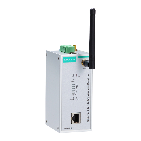
Overview Moxa’s AWK-1121 WLAN Client is ideal for applications that are hard to wire, too expensive to wire, or use mobile equipment that connects over a TCP/IP network. The AWK-1121 is rated to operate at temperatures ranging from 0 to 60°C for standard models and -40 to 75°C for extended temperature models, and is rugged enough for any harsh industrial environment. - Page 3 Panel Layout of the AWK-1121 Top Panel View 1. Grounding screw (M3) 2. Terminal block for PWR1 and PWR2 3. RS-232 console port 4. AUX antenna port 5. System LEDs: PWR, FAULT, and STATE LEDs 6. LEDs for signal strength 7.
-
Page 4: Mounting Dimensions
DIN-Rail Mounting The aluminum DIN-Rail attachment plate should be fixed to the back panel of the AWK-1121 when you take it out of the box. If you need to reattach the DIN-Rail attachment plate to the AWK-1121, make sure the stiff metal spring is situated towards the top, as shown in the figures below. -
Page 5: Wall Mounting (Optional)
STEP 2: Mounting the AWK-1121 to a wall requires 4 screws. Use the AWK-1121 device, with wall mount plates attached, as a guide to mark the correct locations of the 4 screws. The heads of the screws should be less than 6.0 mm in diameter, and the shafts should be less... -
Page 6: Wiring Requirements
Wiring Requirements WARNING Safety First! Be sure to disconnect the power cord before installing and/or wiring your Moxa AWK-1121. WARNING Safety First! Calculate the maximum possible current in each power wire and common wire. Observe all electrical codes dictating the maximum current allowed for each wire size. -
Page 7: Wiring The Redundant Power Inputs
Wiring the Redundant Power Inputs The 4-contact terminal block connector on the AWK-1121’s top panel is used for the AWK-1121’s two DC inputs. The top and front views of the terminal block connector are shown here. STEP 1: Insert the negative/positive DC wires into the V-/V+ terminals. -
Page 8: Communication Connections
The AWK-1121 has one RS-232 (8-pin RJ45) console port located on the top panel. Use either an RJ45-to-DB9 or RJ45-to-DB25 cable to connect the Moxa AWK-1121’s console port to your PC’s COM port. You may then use a console terminal program to access the AWK-1121 for console configuration. -
Page 9: Led Indicators
LED Indicators The front panel of the Moxa AWK-1121 contains several LED indicators. The function of each LED is described in the table below. Color State Description Power is being supplied Green Power is not being supplied Booting Blinking IP address cannot be got from DHCP (slow) server (interval: 1 sec). - Page 10 only support DSSS) • 5.18 to 5.24 GHz (4 channels for W52) Security Firewall for MAC/IP/Protocol/Port-based filtering 64-bit and 128-bit WEP encryption, WPA/WPA2-Personal and Enterprise (IEEE 802.1X/RADIUS, TKIP and AES) Transmission Rates 802.11b: 1, 2, 5.5, 11 Mbps 802.11a/g: 6, 9, 12, 18, 24, 36, 48, 54 Mbps TX Transmit Power 802.11b: •...
- Page 11 Details See www.moxa.com/support/warranty.aspx ATTENTION The AWK-1121 is NOT a portable mobile device and should be located at least 20 cm away from the human body. The AWK-1121 is NOT designed for the general public. To deploy AWK-1121s and establish a wireless network safely, a well-trained technician is required for installation.
- Page 12 AUX antenna (on the top panel) may be selected for use. Make sure the antenna connection matches the antenna configured in the AWK-1121/1127 interface. To protect the connectors and RF module, all radio ports should be terminated by either an antenna or a terminator. The use of the resistive terminator for terminating the unused antenna port is strongly recommended.
Need help?
Do you have a question about the AWK-1121 and is the answer not in the manual?
Questions and answers