Table of Contents
Advertisement
Quick Links
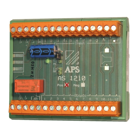
COMMON ALARM INDICATOR
AS1210
OPERATING MANUAL
Safety regulations
Schematics
Function signal inputs normally open NO
Function signal inputs normally closed NC
Operating instructions
Dimension diagram
Technical data
www.aps-systems.ch
for installation
Display
Ordering information
Condition at delivery
page 2
page 3
page 4
page 5
page 6
page 7
page 8
Advertisement
Table of Contents

Subscribe to Our Youtube Channel
Related Manuals for APS AS1210


Summary of Contents for APS AS1210
- Page 1 COMMON ALARM INDICATOR AS1210 OPERATING MANUAL Safety regulations for installation page 2 Schematics page 3 Function signal inputs normally open NO page 4 Function signal inputs normally closed NC page 5 Operating instructions Display Condition at delivery page 6 ...
-
Page 2: Safety Regulations
Installation The AS1210 is snap-mounted onto a DIN or C- rail. The AS1210 has connectors for power supply on both sides, U+ and U-. These are connected internally and may be used as required. It can also be used as a junction box. - Page 3 Schematics Example signal inputs as normally open NO...
- Page 4 Function signal inputs normally open NO Function diagram Description The signal lamps H are designed for fault indicators. As soon as a signal input appears, the respective signal lamp lights up, the optional buzzer and relay are activated. The connected user, e.g. a horn or a lamp, remains activated until the QT button is pressed.
- Page 5 Function signal inputs normally closed NC Function diagram Description The signal lamps H are designed for operation indicators. As soon as a signal input disappears, the respective signal lamp turns off, the optional buzzer and relay are activated. The connected user, e.g. a horn or a lamp, remains acti- vated until the QT button is pressed.
-
Page 6: Condition At Delivery
Relay normally closed NC Inputs normally open NO Inputs normally closed NC Display The AS1210 has a green status LED which indicates the operating mode: LED is blinking: System activated LED lit up: Relay activated Condition at delivery The AS1210 is delivered open with both jumpers. - Page 7 Dimensions...
-
Page 8: Technical Data
35mm DIN-rail EN50022 Fitting C-rail 32mm C-rail EN50035 Ordering information Article number Designation 824.512.05 AS1210 positively switching without buzzer 824.512.06 AS1210 negatively switching without buzzer 824.512.07 AS1210 positively switching with buzzer 824.512.08 AS1210 negatively switching with buzzer APS systems AG...
Need help?
Do you have a question about the AS1210 and is the answer not in the manual?
Questions and answers