
Related Manuals for Ariston CLAS EVO 28 FF


Summary of Contents for Ariston CLAS EVO 28 FF
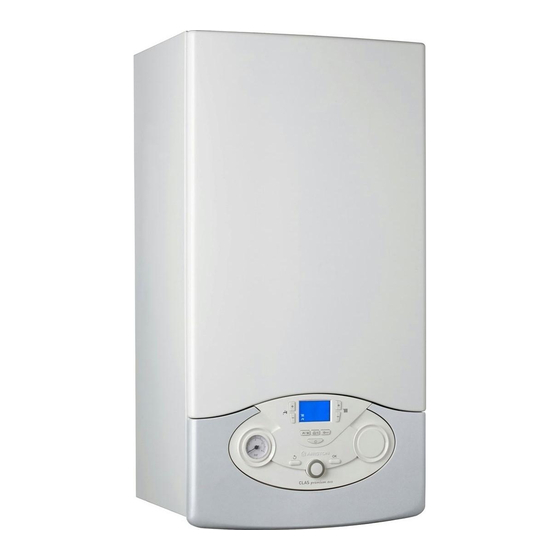
- Page 1 CLAS EVO CLAS EVO SYSTEM CALDAIA MURALE ISTANTANEA WALL-HUNG GAS BOILER CLAS EVO 24 FF CLAS EVO 28 FF CLAS EVO SYSTEM 24 FF CLAS EVO SYSTEM 28 FF CLAS EVO SYSTEM 32 FF...
-
Page 2: Table Of Contents
INDICE INDEX Generalità ......................3 Overview ......................3 Avvertenze per l’installatore ...............3 Advice for the installer ..................3 Marcatura CE ....................3 CE labelling .......................3 Norme di sicurezza ..................4 Safety regulations ..................4 Descrizione del prodotto .................5 Product description ..................5 Pannello comandi ..................5 Control Panel....................5 Display ......................6 Display ........................6... -
Page 3: Generalità
overview Advice for the installer Avvertenze per l’installatore The installation and fi rst ignition of the boiler must be performed L’installazione e la prima accensione della caldaia devono essere by qualifi ed personnel in compliance with current national eff ettuate da personale qualifi cato in conformità alle normative regulations regarding installation, and in conformity with any nazionali di installazione in vigore e ad eventuali prescrizioni requirements established by local authorities and public health... -
Page 4: Norme Di Sicurezza
overview Norme di sicurezza Safety regulations Legenda simboli: Key to symbols: Il mancato rispetto dell’avvertenza comporta rischio di lesioni, in Failure to comply with this warning implies the risk of personal determinate circostanze anche mortali, per le persone injury, in some circumstances even fatal Il mancato rispetto dell’avvertenza comporta rischio di Failure to comply with this warning implies the risk of damage, in danneggiamenti, in determinate circostanze anche gravi, per... -
Page 5: Descrizione Del Prodotto
product description Pannello comandi Control Panel Legenda: Legend : 1. Display 1. Display 2. Tasti +/- regolazione temperatura sanitario 2. Domestic Hot Water adjustment button +/- 3. Tasto MODE - selezione modalità di funzionamento 3. M button (estate / inverno) (Operation mode selection (summer/winter) 4. -
Page 6: Display
product description Display Display Legenda Legend Cifre per indicazione: Digits indicating: - stato caldaia e indicazione - boiler status and temperature °C °C temperaure ( indication ( - Segnalazione codici d’errore (Err) - error code signals (Err) - Richiesta pressione tasto RESET - menu settings (caldaia in blocco) Technical assistance request... -
Page 7: Vista Complessiva
product description Vista complessiva Overall view CLAS EVO SYSTEM 24/28/32 FF CLAS EVO 24/28 FF 14 15 Legend Legenda Flue connector Collettore scarico fumi Air pressure switch Pressostato fumi Condensate discharge Raccoglicondensa Main Heat Exchanger Scambiatore primario C.H. Flow temperature probe Sonda mandata riscaldamento Burner Bruciatore... -
Page 8: Dimensioni Caldaia
product description Dimensioni caldaia Overall Dimensions A. Mandata impianto / bollitore B. Uscita acqua calda CLAS EVO 24/28 FF CLAS EVO SYSTEM 32 FF C. Ingresso Gas D. Entrata acqua fredda CLAS EVO SYSTEM 24/28 FF E. Ritorno Impianto R. Ritorno bollitore (modelli SYSTEM) A. -
Page 9: Dati Tecnici
Dati tecnici Nome modello CLAS EVO 24 FF CLAS EVO 28 FF Certifi cazione CE (pin) 1312BR4793 Tipo caldaia C12-C32-C42-C52-C62-C82-B22-B22p-B32 Portata termica nominale in riscaldamento max/min (Hi) 25,8 / 11,0 30,0 / 13,0 Portata termica nominale in riscaldamento max/min (Hs) -
Page 10: Technical Information
Technical Data Model Name CLAS EVO 24 FF CLAS EVO 28 FF CE certifi cation (pin) 1312BR4793 Boiler type C12-C32-C42-C52-C62-C82-B22-B22p-B32 Max/min nominal heat input(Hi) 25,8 / 11,0 30,0 / 13,0 Max/min nominal heat input (Hs) 28,7 / 12,2... - Page 11 product description Dati tecnici Nome modello CLAS EVO CLAS EVO CLAS EVO SYSTEM 24 FF SYSTEM 28 FF SYSTEM 32 FF Certifi cazione CE (pin) 1312BR4793 1312BR4794 Tipo caldaia C12-C32-C42-C52-C62-C82-B22-B22p-B32 Portata termica nominale in riscaldamento max/min (Hi) 25,8 / 11,0 30,0 / 13,0 32,5 / 14,0 Portata termica nominale in riscaldamento max/min (Hs)
- Page 12 product description Technical Data Model Name CLAS EVO CLAS EVO CLAS EVO SYSTEM 24 FF SYSTEM 28 FF SYSTEM 32 FF CE certifi cation (pin) 1312BR4793 1312BR4794 Boiler type C12-C32-C42-C52-C62-C82-B22-B22p-B32 Max/min nominal heat input(Hi) 25,8 / 11,0 30,0 / 13,0 32,5 / 14,0 Max/min nominal heat input (Hs) 28,7 / 12,2...
-
Page 13: Installazione
installation Before installing the appliance Avvertenze prima dell’installazione The boiler heats water to a temperature below boiling. La caldaia serve a riscaldare l’acqua ad una temperatura inferiore a It should be connected to a heating system and to a domestic quella di ebollizione. -
Page 14: Collegamento Gas
installation Gas connection Collegamento gas The boiler was designed to use gases belonging to the categories as La caldaia è stata progettata per utilizzare gas appartenenti alle shown in the following table. categorie come riportato sulla seguente tabella COUNTRY MODEL CATEGORIES NAZIONE MODELLO... -
Page 15: Rappresentazione Grafi Ca Prevalenza Residua Circolatore
installation Rappresentazione grafi ca della prevalenza residua circolatore Residual Head of the Boiler ΔT 20°C For the measuring of the pipes and of the heating bodies in the Per il dimensionamento delle tubazioni e dei corpi radianti heating system, the residual head value should be calculated as a dell’impianto di riscaldamento si valuti il valore di prevalenza residua in funzione della portata richiesta, secondo i valori riportati sul function of the requested fl ow rate, in accordance with the values... -
Page 16: Schema Idraulico
installation Schema idraulico Water circuit diagram Legenda: Legend: Ventilatore Main Heat Exchanger Scambiatore primario Sonda mandata riscaldamento Central Heating Flow Temperature Probe Burner Bruciatore Ignition Electrodes Elettrodi di accensione Valvola gas Gas Valve Secondary Exchanger Scambiatore secondario Safety valve Valvola di sicurezza 3 bar By-pass automatico 11. -
Page 17: Collegamento Condotti Aspirazione E Scarico Fumi
installation Collegamento condotti aspirazione e scarico fumi Connecting the Flue La caldaia è idonea a funzionare in modalità B prelevando aria The boiler is designed to operate in B mode (by drawing air from the dall’ambiente e in modalità C prelevando aria dall’esterno. room) and in C mode (by drawing air from outside). -
Page 18: Tabella Lunghezze Condotti Aspirazione/Scarico
Table of fl ue gas exhaust duct lengths Lunghezza massima tubi aspirazione/scarico (m) Maximum Extension Exhaust-air Diametro CLAS EVO 24 FF CLAS EVO 28 FF Tipologia di CLAS EVO SYSTEM 32 FF condotti CLAS EVO SYSTEM 24 FF CLAS EVO SYSTEM 28 FF... - Page 19 The diagrams illustrate some of the various designs for coaxial or twin scarico coassiale o sdoppiato. pipe fl ue systems. For further information on discharge/ventilation Per maggiori informazioni relative ad accessori scarico/aspirazione accessories, see the FLUE PIPE ACCESSORIES ARISTON MANUAL. consultare il Catalogo Fumi ARISTON. Sistemi coassiali Coaxial System...
-
Page 20: Collegamenti Elettrici
installation Attenzione! WARNING Prima qualunque intervento nella caldaia togliere Before performing any work on the boiler, fi rst disconnect it from l’alimentazione elettrica tramite l’interruttore bipolare esterno. the electrical power supply using the external bipolar switch. Collegamenti elettrici Electrical connections Per una maggiore sicurezza far eff ettuare da personale qualifi cato un For increased safety, ask a qualifi ed technician to perform a thorough controllo accurato dell’impianto elettrico. -
Page 21: Collegamento Periferiche
installation Collegamento Periferiche Peripheral unit connection Per accedere alle connessioni delle periferiche procedere come segue: To access peripheral unit connections carry out the following steps: - scollegare elettricamente la caldaia - Disconnect the boiler from the power supply - rimuovere il carter sganciandolo dal portastrumenti - Remove the casing by unhooking it from the instrument panel - rimuovere il mantello frontale - Rotate the control panel while pulling it forwards... -
Page 22: Schema Elettrico
installation Schema elettrico caldaia Electrical diagram Per una maggiore sicurezza far eff ettuare da personale qualifi cato un For increased safety, ask a qualifi ed technician to perform a thorough controllo accurato dell’impianto elettrico. check of the electrical system. Il costruttore non è responsabile per eventuali danni causati The manufacturer is not responsible for any damage caused by the dalla mancanza di messa a terra dell’impianto o per anomalie di lack of a suitable earthing system or by the malfunctioning of the... -
Page 23: Messa In Funzione
commissioning Ignition procedure Procedura di accensione Press the ON/OFF button on the control Premere il tasto ON/OFF sul pannello panel to switch on the boiler. The display comandi per accendere la caldaia il shows: display visualizza: ● the operating mode: ●... -
Page 24: Prima Accensione
commissioning Prima accensione First ignition 1. Assicurarsi che: 1. Make sure that: il rubinetto gas sia chiuso; - the gas valve is closed il collegamento elettrico sia stato eff ettuato in modo corretto. - the electrical connection has been properly carried out. Make Assicurarsi in ogni caso che il fi lo di terra verde/giallo sia collegato sure that, in any case, the green/yellow earthing wire is connected ad un effi ciente impianto di terra. -
Page 25: Verifi Ca Delle Regolazioni Gas
commissioning Verifi ca delle regolazioni gas Checking the gas settings Rimuovere il mantello frontale e procedere come sotto riportato. Remove the front casing and proceed as described below. Controllo della pressione di alimentazione. Supply pressure check 1. Allentare la vite “1” (fi g. a) ed inserire il tubo di 1. -
Page 26: Regolazione Della Massima Potenza Riscaldamento
commissioning Controllo della potenza minima Checking the minimum power 1. Per controllare la potenza minima, allentare la vite “2” (fi g.b) ed 1. To check the minimum power level, loosen screw “2” (Fig. b) and inserire il tubo di raccordo del manometro nella presa di pressione. insert the pressure gauge connection pipe into the pipe tap. -
Page 27: Regolazione Della Massima Potenza Riscaldamento Assoluta
commissioning Checking maximum absolute heating power Controllo della potenza massima riscaldamento assoluta ONLY IN CASE OF GAS CHANGE OR P REPLACEMENT SOLO IN CASO DI CAMBIO GAS O SOSTITUZIONE SCHEDA To check/modify the maximum absolute heating power, access Per controllare/modifi care la potenza massima riscaldamento the gas valve and proceed as follows: assoluta accedere alla valvola gas e procedere come segue: 1. -
Page 28: Tabella Riepilogativa Trasformazione Gas
Tabella riepilogativa gas Table summarising changes CLAS EVO 24 FF CLAS EVO 28 FF CLAS EVO SYSTEM 32 FF CLAS EVO SYSTEM 24 FF CLAS EVO SYSTEM 28 FF G230 G230 G230 Indice di Wobbe inferiore (15°C, 1013 mbar) -
Page 29: Funzione Auto
Per attivare la funzione premere il tasto AUTO. To activate the function, press the AUTO button. Per maggiori informazioni consultare il Manuale For further information please refer to the di Termoregolazione di ARISTON. ARISTON temperature adjustment manual. Esempio 1: Example 1:... -
Page 30: Sistemi Di Protezione Caldaia
sistemi di protezione caldaia boiler protection devices Condizioni di arresto dell’apparecchio Appliance shut-off conditions The boiler is protected from malfunctions by means of internal La caldaia è protetta da malfunzionameto tramite controlli interni da checks performed by the electronic P.C.B., which stops the boiler parte della scheda elettronica, che opera se necessario un blocco di from operating if necessary. -
Page 31: Tabella Riepilogativa Codici Errore
sistemi di protezione caldaia boiler protection devices Tabella riepilogativa codici errori Table summarising error codes Central Heating circuit Circuito Primario Display Description Display Descrizione 1 01 Overheat 1 01 Sovratemperatura 1 03 1 03 1 04 1 04 1 05 Insuffi cient circulation 1 05 Circolazione Insuffi ciente... -
Page 32: Analisi Della Combustione
sistemi di protezione caldaia boiler protection devices Analisi della combustione Combustion Analysis La caldaia ha sulla parte esterna del collettore scarico fumi due The fl ue connector has two apertures, readings can be taken for the pozzetti per rilevare la temperatura dei gas combusti e dell’aria temperature of the combustion by-products and of the combustion comburente, concentrazioni di O e CO... -
Page 33: Menù Impostazione - Regolazione - Diagnostica
menù impostazione - regolazione - diagnostica settings - adjustment - problem identifi cation menus Accesso ai Menu di Accessing the settings - adjustment - problem identifi cation impostazione - regolazione - diagnostica menus La caldaia permette di gestire in maniera completa il sistema di The boiler can be used to manage the heating and domestic hot riscaldamento e produzione di acqua calda ad uso sanitario. - Page 34 menù impostazione - regolazione - diagnostica settings - adjustment - problem identifi cation menus I parametri relativi ad ogni singolo menu sono riportati nelle pagine The parameters relating to each individual menu are listed in the following pages. seguenti. The various parameters can be accessed and modifi ed using the O L’accesso e la modifi ca dei vari parametri viene eff ettuata attraverso il button and the encoder (see fi g.
- Page 35 menù impostazione - regolazione - diagnostica settings - adjustment - problem identifi cation menus descrizione range description value note notes SERVICE CODE INSERIMENTO CODICE D’ACCESSO Rotate encoder clockwise to select code 234 and press OK ruotare l’encoder per selezionare 234 e premere il tasto OK 0 NETWORK 0 NETWORK 0 4 DISPLAY SETTING...
- Page 36 menù impostazione - regolazione - diagnostica settings - adjustment - problem identifi cation menus descrizione range description value note notes 2 3 5 Selezione Tipologia 0 = Manuale 2 3 5 Anti-cycling time mode 0 = Manual ritardo d'accensione in 1 = Automatico 1 = Automatic riscaldamento...
- Page 37 menù impostazione - regolazione - diagnostica settings - adjustment - problem identifi cation menus descrizione range description value note notes 2 5 3 Logica spegimento 0 = Anticalcare 2 5 3 D.H.W. switch logic 0 = Anti-scale bruciatore in sanitario (stop a >...
- Page 38 menù impostazione - regolazione - diagnostica settings - adjustment - problem identifi cation menus descrizione range description value note notes 4 PARAMETRI ZONA 1 4 ZONE 1 PARAMETER 4 0 IMPOSTAZIONE TEMPERATURE ZONA 1 4 0 ZONE 1 TEMPERATURE SETTING 4 0 2 Fix temperature central from 35 to 82 (°C) 4 0 2 Impostazione Temperatura...
- Page 39 menù impostazione - regolazione - diagnostica settings - adjustment - problem identifi cation menus descrizione range description value note notes 4 2 4 Impostazione infl uenza da 0 a 20 4 2 4 Room sensor Infl uence from 0 to 20 del sensore ambiente per il to calculate the set- calcolo della temperatura di...
- Page 40 menù impostazione - regolazione - diagnostica settings - adjustment - problem identifi cation menus descrizione range description value note notes 5 2 5 Impostazione temp. massima da 35 a 82 °C 5 2 5 Maximum Central Heating from 35 to 82 °C riscaldamento Zona 2 Temperature Zone 2 5 2 6 Impostazione temperatura...
- Page 41 menù impostazione - regolazione - diagnostica settings - adjustment - problem identifi cation menus descrizione range description value note notes 8 SERVICE PARAMETERS 8 PARAMETRI PER ASSISTENZA TECNICA 8 1 STATISTICHE 8 1 STATISTICHE 8 1 0 Hours Burner On (Central Heating) (XXh) 8 1 0 Numero ore funzionamento bruciatore in riscaldamento (XXh) 8 1 1 Hours Burner On (Domestic Hot Water) (XXh) 8 1 1 Numero ore funzionamento bruciatore in sanitario (XXh)
-
Page 42: Manutenzione
maintenance Istruzioni per l’apertura della mantellatura ed ispezione Instructions for opening the casing and performing an dell’interno internal inspection Prima di qualunque intervento nella caldaia togliere l’alimentazione Before performing any work on the boiler, fi rst disconnect it from the elettrica tramite l’interruttore bipolare esterno e chiudere il rubinetto electrical power supply using the external bipolar switch and shut off del gas. -
Page 43: Note Generali
maintenance La manutenzione è essenziale per la sicurezza, il buon funzionamento Maintenance is an essential part of the safe and effi cient operation of e la durata della caldaia. Va eff ettuata in base a quanto previsto dalle the boiler and ensures its durability. It should be performed according norme vigenti. -
Page 44: Informazioni All'utente
maintenance Controllare periodicamente il pH della miscela acqua-antigelo del used in conjunction with the anti-scaling and anti-corrosion function, circuito caldaia e sostituirla quando il valore misurato è inferiore al in the quantities suggested by the manufacturer, at the mimimum limite prescritto dal produttore dell’antigelo. temperature. -
Page 45: Targhetta Caratteristiche
maintenance Targhetta caratteristicheì Symbols used on the data plate 60/80°C Legenda: Legend : Marchio 14. Portata termica max - min 1. Brand 14. Input rating nominal heating Produttore 15. Potenza termica max - min 2. Manufacturer 15. Power ouput heating Modello - Nr. - Page 48 199 111 222 Servizio clienti Costo della chiamata al telefono fisso: 0,143 Euro al minuto in fascia oraria intera e 0,056 Euro in fascia oraraia ridotta (IVA inclusa) Ariston Thermo SpA Viale A. Merloni, 45 60044 Fabriano (AN) www.aristonthermo.it info.it@aristonthermo.com...
Need help?
Do you have a question about the CLAS EVO 28 FF and is the answer not in the manual?
Questions and answers