Advertisement
Quick Links
Keithley Instruments, Inc.
28775 Aurora Road
Cleveland, Ohio 44139
1-888-KEITHLEY
www.keithley.com
Introduction
This instruction sheet contains a parts list and installation information for the Model 4299-1 Single Unit Adjustable
Heavy-Duty Rack Mount Kit. This kit includes all hardware necessary to mount one Model 260x SourceMeter
Instrument in a standard 19-inch rack.
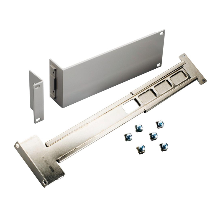
Parts list
Table lists the parts supplied with the Model 4299-1 Single Unit Adjustable Heavy-Duty Rack Mount Kit.
4299-1 parts list
Quantity
Description
1
Front Rack Ear
1
Rear Rack Mount Bracket
1
Rack Mount Extension Arm
6
Cage Nut
1
"DO NOT DISCARD" Label
4
#8-32 X 3/8 LG Phillips Pan Head Screw
2
#10-32 X 3/8 LG Phillips Pan Head Sems Screw
6
#10-32 X 5/8 LG Phillips Truss Head Screw
1
Half Rack Front Panel
PA-908 Rev. B / May 2007
Single Unit Adjustable Heavy-Duty Rack Mount Kit
Keithley Part Number
2602-333
2602-334
2602-335
FA-274
MC-345
8-32X3/8PPH
10-32X3/8PPHSEM
10-32X5/8PHTRSH
2602-344
Model 4299-1
®
1
Advertisement

Related Manuals for Keithley 4299-1


Summary of Contents for Keithley 4299-1
- Page 1 1-888-KEITHLEY www.keithley.com Introduction This instruction sheet contains a parts list and installation information for the Model 4299-1 Single Unit Adjustable ® Heavy-Duty Rack Mount Kit. This kit includes all hardware necessary to mount one Model 260x SourceMeter Instrument in a standard 19-inch rack.
-
Page 2: Installation
Model 4299-1 Installation Instructions Installation The following procedure outlines the installation of the rack mount kit. WARNING Make sure the instrument that is being installed is in a powered down state with all cables unplugged. Failure to install an instrument in a discharged state may cause an electrical shock or death. - Page 3 Model 4299-1 Installation Instructions 1. Remove the handle —The handle serves as an adjustable tilt-bail. Adjust its position by gently pulling it away from the sides of the instrument case and swinging it up or down. To remove the handle, swing the handle below the bottom surface of the case and back until the orientation arrows on the handles line up with the orientation arrows on the mounting ears (refer to Figure 1).
- Page 4 Model 4299-1 Installation Instructions Step 2. Install mounting hardware to instrument NOTE The instrument may be installed on the rack’s right side with the dress panel on the left side as shown in the following illustrations, or on the rack’s left side with the dress panel on the right side (not shown, but similar).
-
Page 5: Step 3. Prepare The Rack
Model 4299-1 Installation Instructions Figure 3 Attach rack ear and dress panel to instrument Front Mounting Holes Pan Head Screw (Phillips) 8-32x3/8PPH (2 Places) Rear Mounting Holes FRONT NOTE** Use Rear Mounting Holes in Front Rack Ear Rack Ear when attaching to a 260x. -
Page 6: Step 4. Install The Instrument
Model 4299-1 Installation Instructions Figure 4 Attach rack mount extension arm Cage Nut FA-274 (4 Places) Front Rack Rails Cage Nut Rear Rack Rails FA-274 (2 Places) Rack Mount Extension Arm (2602-335) Truss Head Screw (Phillips) 10-32x5/8PHTRSH (2 Places) Step 4. Install the instrument... - Page 7 Model 4299-1 Installation Instructions Figure 5 Instrument Installation Rack Mount Extension Arm (2602-335) Rack Rails (not included) Rear Rack Mount Bracket (2602-334) Truss Head Screw (Phillips) 10-32x5/8PHTRSH (2 Places) FRONT Truss Head Screw (Phillips) 10-32x5/8PHTRSH (2 Places) PA-908 Rev. B / May 2007...
Need help?
Do you have a question about the 4299-1 and is the answer not in the manual?
Questions and answers