Sign In
Upload
Manuals
Brands
Curtis Instruments Manuals
Controller
F Series
Curtis Instruments F Series Controller Manuals
Manuals and User Guides for Curtis Instruments F Series Controller. We have
1
Curtis Instruments F Series Controller manual available for free PDF download: Manual
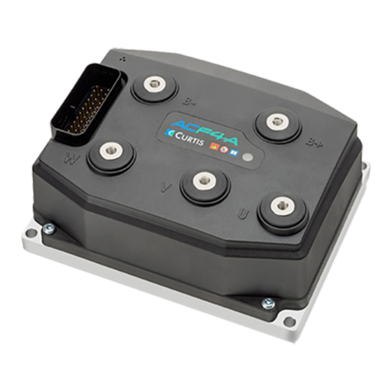
Curtis Instruments F Series Manual (214 pages)
Motor Controller With VCL
Brand:
Curtis Instruments
| Category:
Controller
| Size: 4 MB
Table of Contents
Table of Contents
2
1: Overview
9
Figure 1 AC F4-A Motor Controller
9
How to Use this Manual
10
Getting the most out of Your Curtis Controller
10
2: Installation and Wiring
11
Physically Mounting the Controller
11
Figure 2 AC F4-A Dimensions
11
Precautions
12
High Current Connections
12
Table 1 High Power Connections
12
Figure 3: Battery Power and Motor Phase Terminal Connections
13
Low Current Connections
14
Table 2 the AMPSEAL Connector Components & Part Numbers
14
Figure 4 35-Pin AMPSEAL Connector
14
Rotor Position Feedback (Pins 18, 26, 31, 32)
15
Canbus (Pins 21, 34 and 28, 29)
15
Figure 5 35-Pin AMPSEAL Connection Assignments
15
All Other Low Power Wiring
16
Protected Voltages
16
Table 3 AMPSEAL Connections Protected Voltages
16
Controller Inputs and Outputs
17
Table 4 Logic and Low-Current Connections
17
Controller Wiring Diagram (Examples)
18
Figure 6: Ac F4-A Basic Wiring Diagram
18
Figure 7: Ac F4-A Can Tiller Head Wiring Diagram
19
Figure 7A: Ac F4-A Isolated Can
20
Low Current 35-Pin Connector Electrical Specifications
21
Digital (Switch) Inputs
21
Table 5 Switch (Digital) Inputs Electrical Specifications
21
Analog Inputs
23
Table 6 Analog Inputs Electrical Specifications
23
Potentiometer Inputs with Dynamic Testing
24
Pwm and Digital Drivers
25
Table 7 Potentiometer Input/Configuration Electrical Specifications
25
Table 8 Driver Outputs Electrical Specifications
26
Power Supply Outputs
27
Table 9 Power-Supply Outputs Electrical Specifications
27
Keyswitch and Coil Supply
28
Table 10 Keyswitch and Coil Supply Electrical Specifications
28
Can Ports
29
Table 11 CAN Ports Electrical Specifications
29
Motor Position Sensor Inputs
30
Table 12 Digital/Quadrature Encoder Electrical Specifications
30
Table 13 Sin/Cos Sensor Device Electrical Specifications
31
Motor Temperature Input
32
Table 14 Motor Temperature Sensor Specifications
32
3: Application-Specific Features
33
Motor Speed Constraints
33
Voltage Limits
34
Over-Voltage Region
35
Severe Over-Voltage Region
35
Under-Voltage Region
35
Output-Disabled Region
36
Brownout Voltage
36
Battery Discharge Indicator
36
4: Programmable Parameters
37
Programming Menus
37
Parameter Change Faults [Pcf]
37
Monitor Variables Within Parameter Menus
37
Programming Tools
37
Menu Chart Format
38
Terminology
38
Sdo Write Message
40
Parameter Menus
42
Speed Mode Express
48
Speed Mode
49
Figure 8: Acceleration Rate Response
52
Figure 9: Braking Response Rate
53
Application Setup
56
Figure 10 Throttle Adjustments Diagram
58
Figure 11: Throttle Signal Processing
60
Figure 12: Brake Signal Processing
63
Figure 13: Emergency Reverse Supervision Function
78
Figure 14: Interlock Brake Supervision Speed Limit for Positive Initial Speed
80
Figure 15: Interlock Brake Supervision Speed Limit for Negative Initial Speed
81
Figure 16: Interlock Brake Supervision Distance Check
81
Figure 18: Hydraulic System Diagram, with a Fixed (On/Off) Load-Hold Valve
84
Figure 19: Lift-Input Signal Chain (Processing)
85
Figure 20: Lift-Lowering Signal Chain (Processing)
85
Controller Setup
93
Figure 21: Input 10 Digital and Analog Signal Chain
95
Figure 22: Drive Current Limiting Map
115
Figure 23: Regen Current Limiting Map
116
Ac Motor Setup Menu
117
5: System Monitor
124
Table 16 System Monitor Variables
124
6: Commissioning
135
Initial Setup
135
To Begin
136
Control Mode Selection
136
Parameter Settings - Method Overview
136
Ac Traction Motor Setup Guide
137
Controller Setup Guide
139
Traction Throttle Setup
141
Figure 24: Throttle Related Parameters - Setup Options
142
Voltage Throttle
144
Automated Acim (Motor) Characterization Procedure
150
Traction Systems
151
Tuning Guide
155
Selecting the Control Mode
155
Speed Mode Express Tuning
155
Speed Mode Tuning
156
Other Parameter Tuning
157
Setting up the Hydraulic System
158
Hydraulic Lift and Lower Command Inputs
158
Lift & Lower Switch Inputs
159
Lift Switch Input, with a Proportional Lowering Valve
161
7: Diagnostics and Troubleshooting
163
The Diagnostics Process
163
Troubleshooting Chart Index
168
Fault Actions
172
Table 17 Fault Actions
172
Table 18 Fault Code Troubleshooting Chart
174
8: Maintenance
191
Cleaning
191
Fault History
191
Canopen Pdo Mapping Object Description
192
Example for Rpdo Mapping with the Cit Cit Programmer
194
Example for Tpdo Mapping with the Programmer
196
Example for Rpdo Mapping with Sdo Writes
197
Electromagnetic Compatibility (Emc)
199
Electrostatic Discharge (Esd) Immunity
200
Decommissioning and Recycling the Controller
200
En 13849 Compliance
201
Curtis Integrated Toolkit
203
Creating a Project with a New F-Series Controller
205
Vehicle Can-Port Wiring
212
Specifications: Controller
213
Table E-1 Specifications: AC F4-A Controller
213
Advertisement
Advertisement
Related Products
Curtis Instruments 1212
Curtis Instruments 1212P
Curtis Instruments 1232
Curtis Instruments 1234
Curtis Instruments 1236
Curtis Instruments 1238
Curtis Instruments AC F4-A
Curtis Instruments MultiMode 1230
Curtis Instruments MultiMode 1243 Generation 2
Curtis Instruments PMC 1200 Series
Curtis Instruments Categories
Controller
Touch Panel
I/O Systems
Battery Charger
Motherboard
More Curtis Instruments Manuals
Login
Sign In
OR
Sign in with Facebook
Sign in with Google
Upload manual
Upload from disk
Upload from URL