Advertisement
Quick Links
Advertisement

Related Manuals for DLS Reference ACW68


Summary of Contents for DLS Reference ACW68
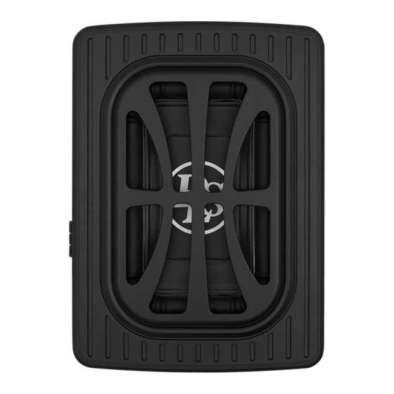
- Page 1 User manual 6”X 8” Active Slim Subwoofer...
-
Page 2: Table Of Contents
Professional tips Product markings Welcome to DLS! Specifications Thank you for buying a DLS Reference ACW68 active slim subwoofer. For us, it’s all about the sound experience. We care deeply about sound and construction quality. In order for your experience to... -
Page 3: Features
”ON” position, the fers because of the 50-60Hz bump in subwoofer auto power on when there is factory radio output. With DLS Bass optimi- signal input. If the amplifierdetect no signal ze control you can tune the low bass in your input, the amplifier will auto turn off. - Page 4 Features 6. Input Gain Control 9. Low Level input After you have installed your system, turn Low level inputs are the recommended way this control to minimum.Turn the head unit to input the audio signal to the subwoofer if on (and the subwoofer willturn on via the RCA outputs are present on your head unit remote connection).
- Page 5 NOTE: Do not connect BOTH the high level and low level inputs from your receiver to your amplifier at the same time. Low Level Input Wiring Low-level (RCA) input wiring is prefered for best audio performance. Most trunk or hatchback installations will require a 15-20 feet RCA cable, while pickup trucks and under seat installations will require a 6-12 feet RCA cable.
- Page 6 Power Terminal Connect to a good chassis ground. The ground connection should be clean, unpainted metal to provide a good electrical connection. Use a wire brush, a scraper or a piece of an abrasive sheet to clean the metal. Remote Terminal Connect the remote terminal to the remote output of the head unit.
-
Page 7: Installation
Installation We include a fixing kit to ensure the subwoofer remains securely mounted. Two types of installation are possible. 4 screws M6*8 Figure 1 4 mounting tabs Under the seat Figure 2 1. The seat must be positioned in its normal fixed position. - Page 8 Installation We include a fixing kit to ensure the subwoofer remains securely mounted. Two types of installation are possible. 4 screws M6*8 Figure 1 4 mounting tabs In the trunk Figure 2 1. Rear seats must be positioned in their normal fixed position.
-
Page 9: Troubleshooting Testing
Troubleshooting testing lf you experience operation or performance problems with this product, compare your installation with the electrical wiring diagram on the previous pages. lf problems persist, read the following troubleshooting tips which may help eliminate the problems. Amplifier will not Check to make sure you have a good ground connection. -
Page 10: Professional Tips
Quasi-balanced signal cables. DLS NOTE! Tweeters can not be tested this way, PRO-cables are Quasi-balanced. double check the connections instead. -
Page 11: Product Markings
European Economic Area (EEA). DLS products complies with the relevant provisions of the RoHS Directive for the European Union. In common with all Electrical and Electronic Equipment (EEE) the product should not be disposed of as household waste. -
Page 12: Specifications
Specifications MODEL DLS ACW68 Power 120 W RMS / 250 W max Max <0.4 % Signal-to-noise ratio >90 dB Frequency response 30 Hz-150 Hz Input sensitivity, high level 0.9 V Input sensitivity, low level 300 mV Low Pass Filter 50 Hz-150 Hz...
Need help?
Do you have a question about the Reference ACW68 and is the answer not in the manual?
Questions and answers