Cisco Firepower 4100 Manual
Hide thumbs
Also See for Firepower 4100:
- Command reference manual (421 pages) ,
- Hardware installation manual (82 pages) ,
- Manual (42 pages)
Table of Contents
Advertisement
Quick Links
Overview
•
•
•
•
•
•
•
•
•
•
•
•
•
•
•
Features
The Cisco Firepower 4100 is a standalone modular security services platform. It is capable of running multiple
security services simultaneously and so is targeted at the data center as a multiservice platform. The series
includes the Firepower 4112, 4115, 4125, and 4145. See
product IDs (PIDs) associated with the 4100 series.
The Firepower 4100 supports Cisco Secure Firewall Threat Defense, Cisco Secure Firewall eXtensible
Operating System (FXOS), and Cisco Secure Firewall ASA software. See
Compatibility, which lists software and hardware compatibility information for the Firepower 4100 series.
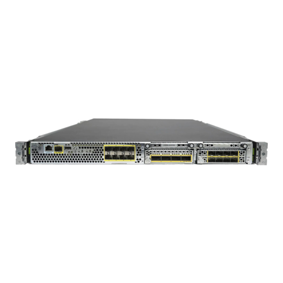
The following figure shows the Firepower 4100.
Features, on page 1
Deployment Options, on page 5
Package Contents, on page 5
Serial Number Location, on page 6
Front Panel, on page 8
Front Panel LEDs, on page 9
Rear Panel, on page 10
Network Modules, on page 11
Hardware Bypass Network Modules, on page 15
Power Supply Modules, on page 22
Fan Modules, on page 24
Supported SFP/SFP+ and QSFP Transceivers, on page 25
Hardware Specifications, on page 28
Product ID Numbers, on page 29
Power Cord Specifications, on page 32
Product ID Numbers, on page 29
Cisco Firepower 4100/9300 FXOS
Overview
for a list of the
1
Advertisement
Table of Contents

Related Manuals for Cisco Firepower 4100


Summary of Contents for Cisco Firepower 4100
-
Page 1: Table Of Contents
Power Cord Specifications, on page 32 Features The Cisco Firepower 4100 is a standalone modular security services platform. It is capable of running multiple security services simultaneously and so is targeted at the data center as a multiservice platform. The series includes the Firepower 4112, 4115, 4125, and 4145. - Page 2 Overview Features Figure 1: Firepower 4100 The following table lists the features for the Firepower 4100. Table 1: Firepower 4100 Features Feature 4112 4115 4125 4145 Security standards — • Common Criteria (CC) certification for the Network Device certifications Collaborative Protection Profile (NDcPPv2.2E), VPN Gateway Module (VPNGW_MOD_v1.1), and Firewall...
- Page 3 Overview Features Feature 4112 4115 4125 4145 Rack mount Slide rails, mount ears, and screws included (4-post EIA-310-D rack) Airflow Front to rear Cold aisle to hot aisle Processor One 12-core Two 12-core Two 16-core Two 22-core 2.1-GHz Intel Xeon 2.1-GHz Intel Xeon 2.1-GHz Intel Xeon 2.1-GHz Intel Xeon...
- Page 4 Overview Features Feature 4112 4115 4125 4145 Supported network • 8-port 10-Gigabit Ethernet SFP+ modules • 4-port 40-Gigabit Ethernet QSFP+ • 8-port 1-Gigabit Ethernet copper with hardware bypass • 2-port 40-Gigabit Ethernet QSFP+ (built-in) with hardware bypass • 6-port 1-Gigabit Ethernet SX fiber SFP (built-in) with hardware bypass •...
-
Page 5: Deployment Options
• In newer spine/leaf data center designs, deployment as a leaf that exclusively offers security functions Package Contents The following figure shows the package contents for the Firepower 4100. Note that the contents are subject to change and your exact contents might contain additional or fewer items. -
Page 6: Serial Number Location
Hardware Installation Guide, the Regulatory and Safety Information Guide, the Getting Started Guide, and the Easy Deployment Guide. Serial Number Location The serial number for the Firepower 4100 series chassis is located on the pullout asset card on the front panel. Overview... - Page 7 Overview Serial Number Location Figure 3: Serial Number on the 4100 Chassis You can also view additional model information on the compliance label located on the bottom of the chassis. Figure 4: Compliance Label on the 4100 Chassis Overview...
-
Page 8: Front Panel
Note RJ-45 Console Port The Firepower 4100 has a standard RJ-45 console port. You can use the CLI to configure your Firepower 4100 through the RJ-45 serial console port by using a terminal server or a terminal emulation program on a computer. -
Page 9: Front Panel Leds
Each port has LEDs that represent link/activity status. Management Port The Firepower 4100 chassis has a management port that requires a 1-Gb fiber or copper SFP. Front Panel LEDs The following figure and table describe the Firepower 4100 front panel LEDs. -
Page 10: Rear Panel
• Blue—Locate is on. Network activity • Off—No connection or port is not in use. • Amber—No link or network failure. • Green—Link up. • Green, flashing—Network activity. Rear Panel The following figure shows the rear panel of the Firepower 4100. Overview... -
Page 11: Network Modules
10 seconds before turning power back ON. Network Modules The Firepower 4100 contains two network module slots that provide optical or electrical network interfaces. Network modules are optional, removable I/O modules that provide either additional ports or different interface types (1/10/40 Gb). - Page 12 Make sure you have the correct firmware package and software version installed to support this network module. For instructions on how to verify your firmware package version and to upgrade the firmware if necessary, see the Cisco Firepower 4100/9300 FXOS Firmware Upgrade Guide. See Cisco Firepower 4100/9300 FXOS Compatibility for the software compatibility matrix.
- Page 13 Make sure you have the correct firmware package and software version installed to support this network module. For instructions on how to verify your firmware package version and to upgrade the firmware if necessary, see the Cisco Firepower 4100/9300 FXOS Firmware Upgrade Guide. See Cisco Firepower 4100/9300 FXOS Compatibility for the software compatibility matrix.
- Page 14 Make sure you have the correct firmware package and software version installed to support this network module. For instructions on how to verify your firmware package version and to upgrade the firmware if necessary, see the Cisco Firepower 4100/9300 FXOS Firmware Upgrade Guide. See Cisco Firepower 4100/9300 FXOS Compatibility for the software compatibility matrix.
-
Page 15: Hardware Bypass Network Modules
Overview Hardware Bypass Network Modules Figure 10: Power LED Network activity LEDs • Off—No connection or port is not in use. • Amber—No link or network failure. • Green—Link up. • Green, flashing—Network activity. Network activity LEDs Ethernet X/1 • Off—No connection or port is not in use. •... - Page 16 Overview 1-Gb Network Module with Hardware Bypass Note When the appliance switches from normal operation to hardware bypass or from hardware bypass back to normal operation, traffic may be interrupted for several seconds. A number of factors can affect the length of the interruption;...
- Page 17 Make sure you have the correct firmware package and software version installed to support this network module. For instructions on how to verify your firmware package version and to upgrade the firmware if necessary, see the Cisco Firepower 4100/9300 FXOS Firmware Upgrade Guide. See Cisco Firepower 4100/9300 FXOS Compatibility for the software compatibility matrix.
- Page 18 Make sure you have the correct firmware package and software version installed to support this network module. For instructions on how to verify your firmware package version and to upgrade the firmware if necessary, see the Cisco Firepower 4100/9300 FXOS Firmware Upgrade Guide. See Cisco Firepower 4100/9300 FXOS Compatibility for the software compatibility matrix.
- Page 19 50 m cable distance Note See the Cisco 40GBASE QSFP Modules Data Sheet for specifications of the QSFP for the 40-Gb BASE-SR-4. We recommend the following Cisco OM3 MTP/MPO cables. Table 3: Cisco Cables Cisco Part Number Cable Length CAB-ETH-40G-5M CAB-ETH-40G-10M...
- Page 20 Overview 1-Gb SX/10-Gb SR/10-Gb LR Network Module with Hardware Bypass Figure 13: FPR4K-NM-6X1SX-F, FPR4K-NM-6X10SR-F, FPR4K-NM-6X10LR-F Captive screw/handle Six network activity LEDs: • Amber—No connection, or port is not in use, or no link or network failure. • Green—Link up, no network activity. •...
- Page 21 Overview 1-Gb SX/10-Gb SR/10-Gb LR Network Module with Hardware Bypass Core diameter (microns) Modal bandwidth Cable distance (MHz/km) Half the Note distance specified by the IEEE standard. Cable and operating 62.5 160 (FDDI) 110 m distance 62.5 200 (OM1) 137 m 250 m 500 (OM2) 275 m...
-
Page 22: Power Supply Modules
Power Supply Modules The Firepower 4100 supports two AC or DC power supply modules so that dual power supply redundancy protection is available. Facing the back of the chassis, the power supply modules are numbered left to right, for example, PSU1 and PSU2. - Page 23 Overview Power Supply Modules Maximum current 13 A (at 100 V AC) The system power requirements are lower than the power Note supply module capabilities. See Hardware Specifications, on page 28 for the system power requirements. Maximum output power 1100 W Frequency 50 to 60 Hz Redundancy...
-
Page 24: Fan Modules
Power supply module is OK and on. Fan Modules The Firepower 4100 requires six fan modules, which are hot-swappable. They are installed in the rear of the chassis. The system supports operation with a single fan failure (N+1 fan redundancy), but do not run the system for an extended amount of time without all fan modules installed. -
Page 25: Supported Sfp/Sfp+ And Qsfp Transceivers
Overview Supported SFP/SFP+ and QSFP Transceivers The fan modules are numbered left to right, for example, FAN1, FAN2, FAN3, FAN4, FAN5, and FAN6. Remove and Replace the Fan Module for the procedure for removing and replacing the fan module. The following figure shows the location of the fan LED. Figure 15: Fan LED Two-color LED The fan module has one two-color LED, which is located on the upper left corner of the fan. - Page 26 Statement 1055 Class 1/1M Laser Invisible laser radiation is present. Do not expose to users of telescopic optics. This applies to Class 1/1M laser products. The following table lists the Cisco supported transceivers. Table 10: Supported Cisco SFP/SFP+ Transceivers Optics Type...
- Page 27 Overview Supported SFP/SFP+ and QSFP Transceivers 1G-ZX GLC-ZX-SMD 1G 1000Base-T GLC-T 1G 1000Base-T GLC-TE 10 Gb 10G-SR SFP-10G-SR 10G-SR-S SFP-10G-SR-S 10G-LR SFP-10G-LR 10G-LR-S SFP-10G-LR-S 10G-LRM SFP-10G-LRM 10G-ER SFP-10G-ER 10G-ER-S SFP-10G-ER-S 10G-ZR-S SFP-10G-ZR-S 10G Cu, 1m SFP-H10GB-CU1M 10G Cu, 1.5m SFP-H10GB-CU1-5M 10G Cu, 2m SFP-H10GB-CU2M 10G Cu, 2.5m...
-
Page 28: Hardware Specifications
QSFP-H40G-ACU 40G-4X10G-CU-A, 7M, 10M QSFP-4X10G-AC 40G-AOC, 1M, 2M, 3M, 5M, 7M, QSFP-H40G-AOC 10M, 15M Hardware Specifications The following table contains hardware specifications for the Firepower 4100. Table 11: Firepower 4100 Hardware Specifications Specification 4112 4115 4125 4145 Dimensions (H x W 1.75 x 16.89 x 29.7 inches (4.44 x 42.90 x 75.43 cm) -
Page 29: Product Id Numbers
87 dB (maximum) Product ID Numbers The following table lists the PIDs associated with the Firepower 4100. All of the PIDs in the table are field-replaceable. If you need to get a return material authorization (RMA) for any component, see... - Page 30 Overview Product ID Numbers Table 12: Firepower 4100 PIDs Description FPR4112-ASA-K9 Cisco Firepower 4112 ASA appliance, 1 RU, two network module bays FPR4112-NGFW-K9 Cisco Firepower 4112 NGFW appliance, 1 RU, two network module bays FPR4112-NGFW-K9 Cisco Firepower 4112 NGIPS appliance, 1 RU, two...
- Page 31 Overview Product ID Numbers Description FPR4K-NM-4X40G 4-port 40-Gb QSFP+ network module FPR4K-NM-4X40G= 4-port 40-Gb QSFP+ network module (spare) FPR4K-NM-6X10LR-F 6-port 10-Gb LR hardware bypass network module FPR4K-NM-6X10LR-F= 6-port 10-Gb LR hardware bypass network module (spare) FPR4K-NM-6X10SR-F 6-port 10-Gb SR hardware bypass network module FPR4K-NM-6X10SR-F= 6-port 10-Gb SR hardware bypass network module (spare)
-
Page 32: Power Cord Specifications
Overview Power Cord Specifications Description FPR4K-CBL-MGMT= Cable management brackets (spare) FPR4K-SSD-BBLKD SSD slot carrier FPR4K-SSD-BBLKD= SSD slot carrier (spare) FPR4K-SSD400 400-GB SSD for Firepower 4112, 4115, and 4125 FPR4K-SSD400= 400-GB SSD for Firepower 4112, 4115, and 4125 (spare) FPR4K-SSD800 800-GB SSD for Firepower 4145 FPR4K-SSD800= 800-GB SSD for Firepower 4145 (spare) Power Cord Specifications... - Page 33 Overview Power Cord Specifications Figure 18: Australia CAB-9K10A-AU Plug: A.S. 3112-2000 Cord set rating: 10 A, 250 V Connector: IEC 60320-C15 — Figure 19: Brazil CAB-250V-10A-BR Plug: EL223 (NBR 14136) Cord set rating: 10 A, 250 V Connector: EL 701B (EN 60320/C13) —...
- Page 34 Overview Power Cord Specifications Figure 21: China CAB-9K10A-CH Plug: CCC GB2099.1, GB1002 Cord set rating: 10 A, 250 V Connector: IEC 60320-C15 — Figure 22: Denmark CAB-TA-DN Plug: DK3 Cord set rating: 10 A, 250 V Connector: IEC 60320-C13 — Figure 23: Europe CAB-AC-EUR Plug: CEE 7/7 Cord set rating: 10 A, 250 V...
- Page 35 Overview Power Cord Specifications Figure 24: India CAB-250V-10A-ID Plug: IS 6538-1971 Cord set rating: 10 A, 250 V Connector: IEC 60320-C13 — Figure 25: Israel CAB-250V-10A-IS Plug: SI-32 Cord set rating: 10 A, 250 V Connector: IEC 60320-C13 — Figure 26: Italy CAB-9K10A-IT Plug: CEI 23-16/VII Cord set rating: 10 A, 250 V Connector: IEC 60320-C15...
- Page 36 Overview Power Cord Specifications Figure 27: Korea CAB-9K10A-KOR Plug: CEE 7/7 Cord set rating: 10 A, 250 V Connector: IEC 60320-C19 — Figure 28: Japan CAB-L620P-C13-JPN Plug: NEMA L6-20P Cord set rating: 15 A, 250 V Connector: IEC 60320-C13 — Figure 29: Japan CAB-TA-JP Plug: NEMA5-15P/JIS 8303 Cord set rating: 12 A, 125 V...
- Page 37 Overview Power Cord Specifications Figure 30: North America CAB-TA-NA Plug: NEMA5-15P Cord set rating: 12 A, 125 V Connector: IEC 60320-C15 — Figure 31: Saudi Arabia ATA187PWRCORD-SAUD Plug: BS1363A/SS145 Cord set rating: 10 A, 250 V Connector: IEC 60320-C13 — Figure 32: South Africa CAB-9K10A-SA Plug: SABS 164 Cord set rating: 10 A, 250 V...
- Page 38 Overview Power Cord Specifications Figure 33: Switzerland CAB-9K10A-SW Plug: SEV 1011 Cord set rating: 10 A, 250 V Connector: IEC 60320-C15 — Figure 34: Taiwan CAB-9K10A-TWN Plug: CNS10917-2 Cord set rating: 10 A, 125 V Connector: IEC 60320-C15 — Figure 35: United Kingdom CP-PWR-CORD-UK Plug: BS1363A/SS145 Cord set rating: 10 A, 250 V Connector: IEC 60320-C13...