Table of Contents
Advertisement
Quick Links
Advertisement
Table of Contents

Related Manuals for IFM PG243


Summary of Contents for IFM PG243
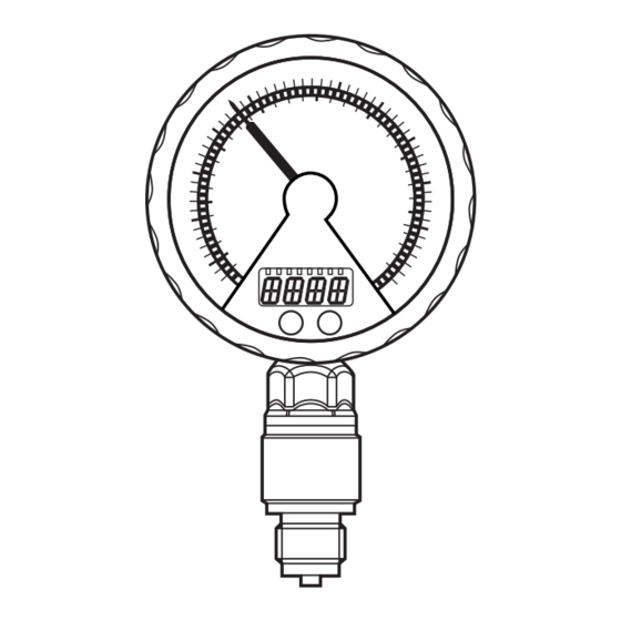
- Page 1 Operating instructions Electronic manometer PG243 PG244...
-
Page 2: Table Of Contents
Contents 1 Preliminary note ���������������������������������������������������������������������������������������������������3 1�1 Symbols used ������������������������������������������������������������������������������������������������3 2 Safety instructions �����������������������������������������������������������������������������������������������4 3 Functions and features ����������������������������������������������������������������������������������������4 3�1 Applications ���������������������������������������������������������������������������������������������������4 4 Function ���������������������������������������������������������������������������������������������������������������5 4�1 Processing of the measured signals ��������������������������������������������������������������5 4�2 Pressure monitoring / switching function �������������������������������������������������������6 4�3 Pressure monitoring / analogue function �������������������������������������������������������7 4�4 Customer-specific calibration ������������������������������������������������������������������������8 5 Installation������������������������������������������������������������������������������������������������������������9 6 Electrical connection ������������������������������������������������������������������������������������������10... -
Page 3: Preliminary Note
9�5 Service functions �����������������������������������������������������������������������������������������22 9�5�1 Read min/max values for system pressure ����������������������������������������22 9�5�2 Reset all parameters to factory setting �����������������������������������������������22 10 Operation ���������������������������������������������������������������������������������������������������������22 10�1 Read set parameters ���������������������������������������������������������������������������������22 10�2 Error indications �����������������������������������������������������������������������������������������22 10�3 Further technical data ��������������������������������������������������������������������������������23 11 Factory setting �������������������������������������������������������������������������������������������������23 1 Preliminary note 1.1 Symbols used ►... -
Page 4: Safety Instructions
2 Safety instructions • The device described is a subcomponent for integration into a system� - The manufacturer is responsible for the safety of the system� - The system manufacturer undertakes to perform a risk assessment and to create a documentation in accordance with legal and normative requirements to be provided to the operator and user of the system�... -
Page 5: Function
• When the damping device is removed, it can become unusable� • When the damping device is removed, the unit can no longer be used under UL conditions� If you have any questions, please contact ifm electronic’s sales specialists� 4 Function 4.1 Processing of the measured signals •... -
Page 6: 4�2 Pressure Monitoring / Switching Function
4.2 Pressure monitoring / switching function OUT1 changes its switching state if it is above or below the set switching limits (SP1, rP1)� The following switching functions can be selected: • Hysteresis function / normally open: [OU1] = [Hno] (→ fig. 1). •... -
Page 7: 4�3 Pressure Monitoring / Analogue Function
4.3 Pressure monitoring / analogue function The analogue output can be configured� • [OU2] defines whether the set measuring range is provided as 4���20 mA ([OU2] = [I]) or as 20���4 mA ([OU2] = [InEG])� Scaling can be set by means of the teaching process or by entering a value for the ASP and AEP parameters�... -
Page 8: 4�4 Customer-Specific Calibration
4.4 Customer-specific calibration The customer-specific calibration changes the curve of measured values compared to the real measured values (shifting / change of the gradient; (→ 9.4.6) [CAL])� • Two calibration points can be defined (CP1, CP2)� The two points are independent of each other�... -
Page 9: Installation
5 Installation Before installing and removing the unit: make sure that no pressure is applied to the system� Note: If 0% is displayed and no pointer is visible, this does not mean that no pressure is applied to the system! We recommend horizontal installation for high medium temperatures�... -
Page 10: Electrical Connection
Pin 3 Pin 4 (OUT1) • Binary switching output pressure monitoring Pin 2 (OUT2) • Analogue output for system pressure Core colours of ifm sockets: 1 = BN (brown), 2 = WH (white), 3 = BU (blue), 4 = BK (black) -
Page 11: Operating And Display Elements
7 Operating and display elements Mode/ Enter 1: Analogue display - Display of the current system pressure in mbar and kPa, bar and kPa or bar and MPa� (→ Depending on the measuring range)� 2: LED ring According to the setting of parameter [LED] (→ 9.2): - Display of set point and reset point�... -
Page 12: Menu
6: Touch button Mode/Enter* - Selection of the parameters and acknowledgement of the parameter values� * The two touch buttons are activated simply by touching / deactivated by releasing the touch button� The touch button must be completely covered to be activated� Slow covering (e�g�... -
Page 13: 8�2 Explanation Of The Main Menu
8.2 Explanation of the main menu SP1/rP1 Upper / lower limit value for system pressure at which OUT1 switches� Output function for OUT1: • Switching signal for the pressure limit values: hysteresis function [H ��] or window function [F ��], either normally open [� no] or normally closed [� nc]� Output function for OUT2: •... -
Page 14: 8�3 Menu Structure: Level 2 (Extended Functions)
8.3 Menu structure: level 2 (extended functions) 1: Change to the main menu... -
Page 15: 8�4 Explanation Of The Menu Level 2
8.4 Explanation of the menu level 2 Standard unit of measurement for system pressure (bar or PSI)� Display mode: SELd • Pressure in the unit set in [Uni]� • Pressure in % of the set scaling of the analogue output� Analogue start point for system pressure: measured value at which 4 mA is provided (20 mA if [OU2] = [InEG])�... -
Page 16: Parameter Setting
9 Parameter setting During parameter setting the unit remains in the operating mode� It continues its monitoring function with the existing parameters until the parameter setting has been completed� Exceptions: changes to the parameters COF (→ 9.4.1), CP1 and CP2 (→ 9.4.6) take effect immediately�... - Page 17 ► Touch [Set] and keep it touched until Enter the valid code no� appears� ► Touch [Mode/Enter] briefly� On delivery by ifm electronic: no access restriction� • Locking / unlocking The unit can be locked electronically to prevent an unintentional operation�...
-
Page 18: 9�2 Configuration Of The Digital Display (Optional)
9.2 Configuration of the digital display (optional) ► Select [Uni] and set the unit of measurement: - [bAr], [mbAr], [MPa], [kPa]� The available unit of measurement depends on the measuring range� ► Select [SELd] and set type of indication: - [P]: system pressure in the unit set in Uni� - [P%]: system pressure in % of the set scaling of the analogue output;... -
Page 19: 9�3 Set Output Signals
9.3 Set output signals 9.3.1 Set output functions ► Select [OU1] and set the switching function: - [Hno] = hysteresis function/NO� - [Hnc] = hysteresis function/NC� - [Fno] = window function/NO� - [Fnc] = window function/NC� ► Select [OU2 ] and set the analogue function: - [I] = current signal proportional to pressure 4…20 mA�... -
Page 20: 9�4 User Settings (Optional)
As an alternative: ► Select [ASP] and set the measured value at which 4 mA is provided (20 mA at [OU2] = [InEG])� ► Select [AEP] and set the measured value at which 20 mA is provided (4 mA at [OU2] = [InEG])� Minimum distance between ASP and AEP = 25 % of the final value of the measuring range (turn-down 1:4)�... -
Page 21: 9�4�5 Set Damping For The Analogue Signal
9.4.5 Set damping for the analogue signal ► Select [dAA] and set a value between 0�01 and 30 s� dAA value = response time between pressure change and change of the analogue signal in seconds� 9.4.6 Calibrate curve of measured values If the unit is to adopt the settings for the calibration points, the following conditions must be adhered to: - CP1 and CP2 must be within the measuring range (i�e�... - Page 22 9.5 Service functions 9.5.1 Read min/max values for system pressure ► Select [HI] or [LO] and touch [Set] briefly� [HI] = maximum value, [LO] = minimum value� Delete memory: ► Select [HI] or [LO]� ► Touch [Set] and keep it touched until [----] is displayed� ►...
- Page 23 10.3 Further technical data Further technical data and scale drawing at www�ifm�com� 11 Factory setting Factory setting User setting 25,0 % VMR* 24,9 % VMR* ASP / tASP 0 % VMR* AEP / tAEP 100 % VMR* COF / tCOF...
Need help?
Do you have a question about the PG243 and is the answer not in the manual?
Questions and answers