Table of Contents
Advertisement
Quick Links
Advertisement
Table of Contents

Subscribe to Our Youtube Channel
Related Manuals for Zmotion XPLC300


Summary of Contents for Zmotion XPLC300
- Page 2 This manual is copyrighted by Shenzhen Technology Co., Ltd., without the written permission of the Zmotion Technology, no person shall reproduce, translate and copy any content in this manual. The above-mentioned actions will constitute an infringement of the copyright of the company's manual, and Zmotion will investigate legal responsibility according to law.
- Page 3 ⚫ Zmotion will not take any legal responsibility for personal safety accidents and property losses caused by failure to comply with the contents of this manual or illegal operation of products. Safety Level Definition According to the level, it can be divided into "...
- Page 4 ◆ Improper installation of the controller may result in misoperation, failure and fire. Wiring ◆ The specifications and installation methods of the external wiring of the equipment shall comply with the requirements of local power distribution regulations. ◆ When wiring, all external power supplies used by the system should be disconnected before operation.
-
Page 5: Table Of Contents
Local IO Offset Configuration ............... 23 4.2.2. Local Analog Offset Configuration ............24 4.2.3. IO Offset Configuration for ZMIO Expansion (that comes with XPLC300 controller) ......................24 4.2.4. Analog Offset Configuration for ZMIO Expansion (that comes with XPLC300 controller) .................... 24... - Page 6 XPLC300 Motion Controller Hardware Manual V1.5 5.1. ZDevelop Software Usage ................26 5.2. PC Upper-Computer Program Application ............. 31 Chapter VI Run and Maintain .................... 34 6.1. Regular Inspection and Maintenance ............. 34 6.2. Common Problems ..................35...
-
Page 7: Chapter I Production Information
Chapter I Production Information 1.1. Product Information XPLC300 motion controllers is a kind of EtherCAT vertical fieldbus motion controller that supports ladder diagram programming. The controller itself supports max 16 axes to achieve point to point, linear interpolation, electronic cam and other control requirements. -
Page 8: System Frame
XPLC300 Motion Controller Hardware Manual V1.5 ◆ Support secondary development on all kinds of PC platforms. ◆ Support multi-file and multi-task programming in ZBasic, and PC program and controller inner program can work at the same time. ◆ A variety of program encryption methods to protect the intellectual property rights of customers. -
Page 9: Hardware Installment
XPLC300 Motion Controller Hardware Manual V1.5 1.4. Hardware Installment → Unit: mm → Installation Step: ➢ Please use 35mm standard DIN guide rail. ➢ Open guide rail buckle of ECAT communication module, then embed the controller in the DIN guide rail. - Page 10 XPLC300 Motion Controller Hardware Manual V1.5 ⚫ In order to facilitate ventilation and controller replacement, 2-3cm should be left between the upper and lower parts of the controller and the installation environment and surrounding components. Considering the convenient operation and maintenance of the ⚫...
-
Page 11: Chapter Ii Product Specification
XPLC300 Motion Controller Hardware Manual V1.5 Chapter II Product Specification 2.1. Basic Specification Item Description Basic Axes There are 4/6/8/12 axes Max Extended Axes Type of Basic Axes EtherCAT bus axes (no pulse axes and ecoder) Digital IO 1 input and no output... -
Page 12: Nameplate Information
XPLC300 Motion Controller Hardware Manual V1.5 2.2. Nameplate Information Here shows XPLC312E, others are the same rule. → Model description: 2.3. Order Information Model Axes Encoder Total axes IN/OUT AD/DA Description XPLC304E Point to point, XPLC306E linear XPLC308E interpolation, electronic cam... -
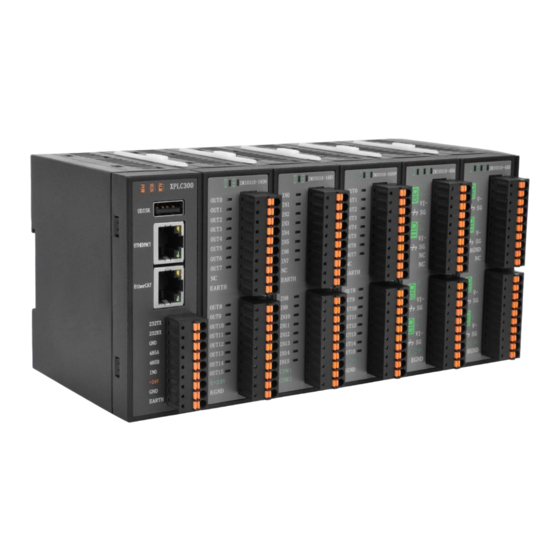
Page 13: Interface Definition
XPLC300 Motion Controller Hardware Manual V1.5 2.4. Interface Definition → Interface Description Mark Interface Number Description Power state: green, it lights when power is conducted. The led that indicates the current state. Run state: green, it lights when runs normally... -
Page 14: Work Environment
XPLC300 Motion Controller Hardware Manual V1.5 command, default IP address is 192.168.0.11 UDISK U disk interface Insert U disk equipment 24V DC power, it supplies the power for E+24V Main power supply controller. 2.5. Work Environment Item Parameters Work Temperature -20℃-60℃... -
Page 15: Chapter Iii Wiring, Communication Configuration
XPLC300 Motion Controller Hardware Manual V1.5 Chapter Wiring, Communication Configuration & 3.1. User Terminal The user terminal adopts a 9Pin (there are all 3 terminals) screw-type pluggable wiring terminal, and the interval (means the gap distance between two ports) should be 3.81mm. -
Page 16: Rs485, Rs232 Communication Specification & Wiring
XPLC300 Motion Controller Hardware Manual V1.5 Voltage DC24V(-10%~10%) The current to open ≤0.5A The current to work ≤0.4A Anti-reverse connection Valid Overcurrent Protection Valid 3.1.2. RS485, RS232 Communication Specification & Wiring RS485 serial port supports MODBUS_RTU protocol and custom communication, mainly including 485A, 485B and public end. - Page 17 XPLC300 Motion Controller Hardware Manual V1.5 Connect 232RX and 232TX of RS232 to 232RX and 232TX of the controller correspondingly, and connect the public ends “GND” of RS232 communication parties together. → Wiring Notes: As above, the daisy chain topology is used for wiring (the star topology structure ⚫...
-
Page 18: Basic Usage Method
XPLC300 Motion Controller Hardware Manual V1.5 weak current, it is recommended for the distance to be more than 20cm. It should be noted that the equipment grounding (chassis) on the entire line must be ⚫ good, and the grounding of the chassis should be connected to the standard factory ground pile. -
Page 19: Digital Input Specification & Wiring
XPLC300 Motion Controller Hardware Manual V1.5 “ZBasic Programming Manual” for details. (5) According to their respectively instructions, correctly set the relevant parameters of the third-party equipment to match the parameters of each node. (6) Correctly set the "address" and "speed" of the slave station expansion module according to the manual of the slave station. - Page 20 XPLC300 Motion Controller Hardware Manual V1.5 Max current -6mA (negative) Isolation mode optoelectronic isolation Note: the above parameters are standard values when the voltage of controller power supply (E+24V port) is 24V. → Wiring Reference → Wiring Note: The wiring principle of high-speed digital input IN (0) is shown in the figure above.
-
Page 21: Basic Usage Method
“ZDevelop/View/In”. Please refer to “ZBasic” for details. 3.2. U Disk XPLC300 series motion controller provides a USB communication interface, which can insert the U disk device. It is used for ZAR program upgrading, controller data importing and exporting, file 3 executing, etc. -
Page 22: Ethernet
500mA Whether Isolates 3.3. ETHERNET XPLC300 motion controller has a 100M network port, and it supports MODBUS_TCP protocol and custom communication, the default IP address is 192.168.0.11. The pin definition is as follows: The Ethernet port of the controller can be connected to a computer, HMI, etc. through an Ethernet cable, and using point to point connection method. -
Page 23: Ethercat Bus Interface
XPLC300 Motion Controller Hardware Manual V1.5 3.4. EtherCAT Bus Interface XPLC300 motion controller has a 100M EtherCAT communication interface, and it supports EtherCAT protocol. In addition, EtherCAT driver or EtherCAT expansion module can be connected. The pin definition is as follows: →... - Page 24 XPLC300 Motion Controller Hardware Manual V1.5 → Communication Cable Requirements Both ETHERNET communication interface and EtherCAT communication interface adopt standard Ethernet RJ45 interface. The network cable adopts Category 5e STP, and the crystal head has a metal shell to reduce interference and to prevent information from being eavesdropped. As shown below:...
- Page 25 XPLC300 Motion Controller Hardware Manual V1.5 →Cable production steps: Strip the cable insulation, the exposed copper part depends on the size of the tube- ⚫ type pre-insulated terminal. Pass the conductor part of the cable into the tubular pre-insulated terminal and crimp ⚫...
-
Page 26: Chapter Iv Expansion Module
Open the gap clips of all modules. ⚫ Align the local expansion front-end interface of the expansion sub-module with the ⚫ local expansion rear-end interface of the XPLC300 series controller (or expansion sub-module). Press the gap clips of all modules together. ⚫... -
Page 27: Function Configuration
Configuration includes local offset configuration and built-in ZMIO expansion configuration, which can be further divided into IO configuration and analog configuration. 4.2.1. Local IO Offset Configuration Functional Description It is used to offset local IO address of XPLC300 controllers. Grammar LOCALIO_OFFSET=value Parameter List... -
Page 28: Local Analog Offset Configuration
AIO starting address Example LOCALAIO_ADDRESS=8 ‘local AIO address is offset to 1 Note: there is no analogs for XPLC300 series controllers, no offset configuration effect. 4.2.3. IO Offset Configuration for ZMIO Expansion (that comes with XPLC300 controller) It is used to offset local IO address of ZMIO300 expansion Functional Description that comes with XPLC300 controllers. - Page 29 ‘local AIO address brought by ZMIO expansion is offset to 33 Controller status (before modification): Controller status (after modification): How to check the situation of ZMIO expansion brought by XPLC300 controller: Functional It is used to check the situation of ZMIO expansion brought by XPLC300 Description controller.
-
Page 30: Chapter V Program & Applications
5.1. ZDevelop Software Usage ZDevelop is a PC-side program development, debugging and diagnostic software for the ZMoiton series motion controllers of Zmotion Technology. Through it, users can easily edit and configure the controller program, quickly develop applications, diagnose system operating parameters in real time, and watch the motion controller. The running program is debugged in real time and supports Chinese and English bilingual environments. - Page 31 XPLC300 Motion Controller Hardware Manual V1.5 Click “File” – “New File”, select file type to build, here select Basic, click “OK”. Double click “AutoRun”, enter task number 0.
- Page 32 XPLC300 Motion Controller Hardware Manual V1.5 Edit program program editing window, click “save”, built basic file will be saved under “zpj.” project automatically. “Save all” means all files under this project will be saved. Click “controller – connect”, if no...
- Page 33 XPLC300 Motion Controller Hardware Manual V1.5 parameters port address, then click “connect”. Click “Ram/Rom” – “download RAM download ROM”, if it is successful, there is print indication, the same time, program downloaded into controller runs automatically. RAM: it will not...
- Page 34 XPLC300 Motion Controller Hardware Manual V1.5 Click “Debug” – “Start/Stop Debug” to call “Task” “Watch” window, because it was downloaded before, here select “Attach the current”. Click “View” – “Scope” to open oscilloscope. Note: ⚫ When opening an project, choose to open the zpj file of the project. If only the Bas file is opened, the program cannot be downloaded to the controller.
-
Page 35: Pc Upper-Computer Program Application
Mac, Android, and wince, and provides dll libraries in various environments such as vc, c#, vb.net, and labview, as shown in the figure below. PC software programming refers to "ZMotion PC Function Library Programming Manual". The program developed using the PC software cannot be downloaded to the controller, and it is connected to the controller through the dll dynamic library. - Page 36 XPLC300 Motion Controller Hardware Manual V1.5 Select development language “Visual C++” and the select program type “MFC application type”. Select “Based on basic box”, click “next” or “finish” Find function library provided manufacturer. Routine below (64-bit library) Copy all DLL related library files under the above path to the newly created project.
- Page 37 XPLC300 Motion Controller Hardware Manual V1.5 zmotion.lib Item". Related header 2) Add static files: libraries and zauxdll2.h, related zmotion.h header files in sequence in the pop-up window. Declare relevant header files and define controller connection handle, so far the project is...
-
Page 38: Chapter Vi Run And Maintain
XPLC300 Motion Controller Hardware Manual V1.5 Chapter VI Run and Maintain The correct operation and maintenance of the motion controller can not only guarantee and extend the life cycle of the equipment itself, but also take technical management measures according to the pre-specified plan or the corresponding technical conditions to prevent equipment performance degradation or reduce the probability of equipment failure. -
Page 39: Common Problems
XPLC300 Motion Controller Hardware Manual V1.5 Should be within the range of Whether the controller is subjected to vibration resistance vibration or shock impact resistance Keep good ventilation and Is the heat dissipation good heat dissipation The mounting screws should... - Page 40 XPLC300 Motion Controller Hardware Manual V1.5 invalid. and whether the "input" view can watch the signal change of the limit sensor. Check whether the mapping of the limit switch is correct. Check whether the limit sensor is connected to the common terminal of the controller.
- Page 41 XPLC300 Motion Controller Hardware Manual V1.5 Check master-slave configuration, communication speed configuration, etc. Check the DIP switch to see if there are multiple expansion modules with the same ID. Use twisted-pair cables, ground the shielding layer, and use dual power supplies for severe interference...
Need help?
Do you have a question about the XPLC300 and is the answer not in the manual?
Questions and answers