Table of Contents
Advertisement
Quick Links
Advertisement
Table of Contents

Related Manuals for MSI G52-M7246X1


Summary of Contents for MSI G52-M7246X1
- Page 1 975X Platinum Series MS-7246 (v1.X) ATX Mainboard G52-M7246X1...
- Page 2 FCC-B Radio Frequency Interference Statement This equipment has been tested and found to comply with the limits for a class B digital device, pursuant to part 15 of the FCC rules. These limits are designed to provide reasonable protection against harmful interference in a residential installation. This equipment generates, uses and can radiate radio frequency energy and, if not installed and used in accordance with the instruction manual, may cause harmful interference to radio communications.
-
Page 3: Copyright Notice
Copyright Notice T he material in this document is the intellec tual property of M ICRO-STAR INTERNATIONAL. W e take every care in the preparation of this document, but no guarantee is given as to the correctness of its contents. Our products are under continual improvement and we reserve the right to make changes without notice. -
Page 4: Technical Support
Alternatively, please try the following help resources for further guidance. † Visit the MSI homepage & FAQ site for technical guide, BIOS updates, driver updates, and other information: http://www.msi.com.tw & http://www.msi. -
Page 5: Weee Statement
WEEE Statement... -
Page 8: Table Of Contents
CONTENTS FCC-B Radio Frequency Interference Statement ............ii Copyright Notice ......................iii Technical Support ......................iv Safety Instructions ......................iv WEEE Statement ......................v Chapter 1. Getting Started ..................1-1 Mainboard Specifications ................... 1-2 Mainboard Layout ....................1-4 Packing Contents ....................1-5 Chapter 2. - Page 9 IrDA Infrared Module Header: JIR ............. 2-17 Front USB Connectors: JUSB1 / JUSB2 ..........2-18 Front Panel Audio Connector: JAUD1 ............2-18 IEEE 1394 Connector: J1394_1(Optional) ..........2-19 Chassis Intrusion Switch Connector: JCI1 ..........2-19 D-Bracket™ 2 Connector: JLED1 ............. 2-20 Button .........................
- Page 10 MEGA STICK ....................... 4-10 Basic Function ................... 4-10 Non-Unicode programs supported ............4-12 Core Center ......................4-14 Left-wing: Current system status ............4-15 Right-wing: PC hardware status during real time operation ....4-15 Power on Agent ....................4-16 Power On ....................4-16 Power Off / Restart ...................
- Page 11 Sound Effect ....................7-5 Mixer ......................7-8 Audio I/O ..................... 7-12 Microphone ....................7-17 3D Audio Demo ................... 7-18 Information ....................7-19 Using 2-, 4-, 6- & 8- Channel Audio Function ..........7-21...
-
Page 12: Chapter 1. Getting Started
Getting Started Chap t er 1 . Ge tting Started Getting Started Thank you for choosing the 975X Platinum Series (MS-7246) v1.x ATX mainboard. The 975X Platinum Series mainboard is based ® ® on Intel 975X and Intel ICH7R chipset for optimal system efficiency. ®... -
Page 13: Mainboard Specifications
Pentium 4, Pentium D, Pentium 4 Extreme Edition and Pentium Ex- treme Edition LGA775 processors in LGA775 package. † Support Cedar Mill Value Processor † Supports 4-pin CPU Fan pin header with Fan Speed Control. (For the latest information about CPU, please visit http://www.msi.com.tw/program/ products/mainboard/mbd/pro_mbd_cpu_support.php) Chipset † Intel ®... - Page 14 Getting Started † One PCI Express to PATA/ SATAII Host controller integrated in JMicron JMB361. - Supports connect up to 1 Ultra ATA drives. - Supports 1 SATAII drive. - Supports SATA+PATA RAID 0/ RAID 1 mode. On-Board Peripherals † On-Board Peripherals include: - 1 floppy port supports 1 FDD with 360K, 720K, 1.2M, 1.44M and 2.88Mbytes - 1 serial port - 1 parallel port supports SPP/EPP/ECP mode...
-
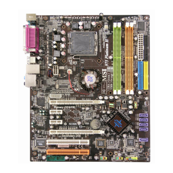
Page 15: Mainboard Layout
M S-7246 ATX Mainboard Mainboard Layout JCI1 Top : mouse Bottom: keyboard PWR_FAN Winbond W83627EHG Top : Paralle l Port Bottom: COM A 1394 Port (opti onal) SPDIF (Coaxial) USB ports CPU_FAN T: LAN jack Intel B: USB ports 975X NB_FAN Line-In Line-Ou t... -
Page 16: Packing Contents
Getting Started Packing Contents MSI Driver/Utility CD SATA Cable MSI motherboard Standard Cable for Standard Cable for Power Cable Floppy Disk IDE Devices D-Bracket 2 IEEE1394-Bracket Back IO Shield (Optional) (Optional) * The pictures are for reference only and may vary f rom the pac king c ontents of the product you User’s Guide... -
Page 17: Chapter 2. Hardware Setup
Hardware Setup Chapter 2. Hardware Setup Hardware Setup This chapter tells you how to install the CPU, memory modules, and expansion cards, as well as how to setup the jumpers on the mainboard. Also, it provides the instructions on connecting the periph- eral devices, such as the mouse, keyboard, etc. -
Page 18: Quick Components Guide
M S-7246 ATX Mainboard Quick Components Guide CPU, p.2-3 PWR_FAN, p2-14 CPU_FAN, p2-14 NB_FAN, p2-14 DIMM1/2/3/4, p.2-7 JPW, p.2-9 JCI1, p2-19 ATX, p.2-9 FDD, p.2-14 Back Panel, p.2-10 IDE1/IDE2, p.2-15 JPWR, p.2-9 PCIE_X16, SYS_FAN, p.2-24 p.2-14 JIR, p.2-17 JCD1, p.2-17 SATA1~4, PCIE_X1, p.2-16... -
Page 19: Central Processing Unit: Cpu
W hen you are installing the CPU, make sure to install the cooler to prevent overheating. If you do not have the CPU cooler, contact your dealer to purchase and install them before turning on the computer. For the latest information about CPU, please visit http://www.msi.com.tw/pro- gram/products/mainboard/mbd/pro_mbd_cpu_support.php. MSI Reminds You... -
Page 20: Cpu & Cooler Installation
CPU Clip to clip the CPU up, pressing the clips on both sides to the center, as the arrows shown. MSI Reminds You... 1. Confirm if your CPU cooler is firmly installed before turning on your system. - Page 21 Hardware Setup 5. The CPU has a plastic cap on it to 6. Remove the cap from lever hinge side protect the contact from damage. (as the arrow shows). The pins of Before you have installed the CPU, socket reveal. always cover it to protect the socket pin.
- Page 22 CPU. MSI Reminds You... 1. Check the information in PC Health Status of H/W M onitor in BIOS (Chapter 3) for the CPU temperature. 2. Whenever CPU is not installed, always protect your CPU socket pin with the plastic cap covered (shown in Figure 1) to avoid damaging.
-
Page 23: Memory
DDRII memory module in the DDRII slot. Otherwise, you are not able to boot up your system and your mainboard might be damaged. For the updated supporting memory modules, please visit http://www.msi. com.tw/program/products/mainboard/mbd/pro_mbd_trp_list.php. DIMM1~DIMM4 (from left (Greem) to right(Orange)) Channel A (DIMM1 &... -
Page 24: Installing Ddrii Modules
256MB~2GB 256MB~2GB 256MB~2GB 1GB~8GB MSI Reminds You... - Dual-channel DDRII works ONLY in the 5 combinations listed in the table shown in the previous page. - Please select the identical memory modules to install on the dual channel, and DO NOT install three memory modules on three DIMMs, or it may cause some failure. -
Page 25: Power Supply
+12V JPWR +12V MSI Reminds You... 1. These three connectors connect to the ATX power supply and have to work together to ensure stable operation of the mainboard. 2. Power supply of 450 watts (and above) is highly recommended for system stability. -
Page 26: Back Panel
M S-7246 ATX Mainboard Back Panel The back panel provides the following connectors: RS-Out L-In Parallel M ou se SPDIF IEEE1394 USB Ports Keyboard COM Port L-Out CS-Out (optional) SPDIF Mouse/Keyboard Connector ® The mainboard provides a standard PS/2 mouse/keyboard mini DIN connector ®... -
Page 27: Serial Port Connector: Com Port
Hardware Setup Serial Port Connector: COM Port The mainboard offers one 9-pin male DIN connector COM Port. It’s a 16550A high speed communication port that send/receive/ 16 bytes FIFOs. You can attach a serial mouse or other serial device directly to it. Pin Definition SIGNAL DESCRIPTION... -
Page 28: Lan (Rj-45) Jack
Center/Subwoofer Line Out Speaker Out ( in 7.1CH / 5.1CH) (Front R/L) M IC SPDIF-Out MSI Reminds You... For the advanced functions of the audio codec, please refer to Chapter 7: Introduction to Realtek ALC883 Audio Codec for details. 2-12... -
Page 29: Parallel Port Connector: Lpt1
Hardware Setup Parallel Port Connector: LPT1 The mainboard provides a 25-pin female centronic connector as LPT. A parallel port is a standard printer port that supports Enhanced Parallel Port (EPP) and Ex- tended Capabilities Parallel Port (ECP) mode. Pin Definition SIGNAL DESCRIPTION STROBE... -
Page 30: Connectors
SENSOR Control CPU_ FAN SYS_ FAN PW R_ FAN NB _ F AN MSI Reminds You... 1. Always consult the vendors for proper CPU cooling fan. ® 2. Please refer to the recommended CPU fans at Intel official website. 2-14... -
Page 31: Hard Disk Connector: Ide1/ Ide2
IDE2 (Secondary IDE Connector) IDE2 only can connect a Master drive. MSI Reminds You... If you install two hard disks on cable, you must configure the second drive to Slave mode by setting its jumper. Refer to the hard disk documentation supplied by hard disk vendors for jumper setting instructions. -
Page 32: Sataii Connectors Controlled By Intel Ich7R: Sata1~Sata4
Take out the dust cover and connect to the hard disk devices Connect to serial ATA ports MSI Reminds You... Please do not fold the serial ATA cable in a 90-degree angle, since this might cause the loss of data during the transmission. 2-16... -
Page 33: Front Panel Connectors: Jfp1 / Jfp2
Hardware Setup Front Panel Connectors: JFP1 / JFP2 The mainboard provides two front panel connectors for electrical connection ® to the front panel switches and LEDs. JFP1 is compliant with Intel Front Panel I/O Connectivity Design Guide. JFP1 Pin Definition SIGNAL DESCRIPTION Power... -
Page 34: Front Usb Connectors: Jusb1 / Jusb2
USB0+ USB1+ (USB 2.0/standard spec) USBOC MSI Reminds You... Note that the pins of VCC and GND must be connected correctly, or it may cause some damage. Front Panel Audio Connector: JAUD1 The JAUD1 front panel audio connector allows you to connect to the front ®... -
Page 35: Ieee 1394 Connector: J1394_1(Optional)
Hardware Setup IEEE 1394 Connector: J1394_1(Optional) The mainboard provides one 1394 pin header that allow you to connect op- tional IEEE 1394 port. Pin Definition SIGNAL SIGNAL TPA+ TPA- Ground Ground TPB+ TPB- J1394_1 Cable power Cable power Key (no pin) Ground How to attach the IEEE 1394 Port: Connected to J1394_1 (Green connector) -
Page 36: D-Bracket™ 2 Connector: Jled1
M S-7246 ATX Mainboard D-Bracket™ 2 Connector: JLED1 The mainboard comes with a JLED1 connector for you to connect to D-Bracket™ 2. D-Bracket™ 2 is a USB Bracket that supports both USB1.1 & 2.0 spec. It integrates four LEDs and allows users to identify system problem through 16 various combina- tions of LED signals. - Page 37 Hardware Setup G reen Description D-Bracket™ 2 System Power ON The D-LED will hang here if the processor is damaged or not installed properly. Early Chipset Initialization Memory Detection Test Testing onboard memory size. The D-LED will hang if the memory module is damaged or not installed properly.
- Page 38 M S-7246 ATX Mainboard D-Bracket™ 2 Description BIOS Sign On This will start showing information about logo, proces- sor brand name, etc... Testing Base and Extended Memory Testing base memory from 240K to 640K and extended memory above 1MB using various patterns. Assign Resources to all ISA.
-
Page 39: Button
OS every time it is turned on. If you want to clear the system configuration, use the SW (Clear CMOS Button) to clear data. Press the button to clear the data. MSI Reminds You... Make sure that you power off the system before clearing CMOS data. -
Page 40: Slots
M S-7246 ATX Mainboard Slots The mainboard provides 2 PCI Express x16 slots, 2 PCI Express x1 slots and 2 PCI bus slots. It supports 2 PCIE x 16 slots transfer into 2 PCIE x 8 ports (CrossFire Technology). PCI Express Slots The PCI Express slots, as a high-bandwidth, low pin count, serial, intercon- nect technology, support Intel highest performance desktop platforms utilizing the Intel Pentium 4 processor with HT Technology. - Page 41 DMS connector DVI connector DVI connector (connectting to the monitor) MSI Reminds You... 1. Mainboard photos shown in this section are for demonstration only. The appearance of your mainboard may vary depending on the model you purchase. ®...
- Page 42 CrossFire™ to operate. The following aspect appears in Catalyst™ Control Center: Select the Advanced View f rom t h e view drop menu. MSI Reminds You... A CrossFire™ system has four possible display modes: • SuperTiling • Scissor Mode • Alternate Frame Rendering • Super Anti-aliasing.
-
Page 43: Pci (Peripheral Component Interconnect) Slots
Hardware Setup PCI (Peripheral Component Interconnect) Slots The PCI slots allow you to insert the expansion cards to meet your needs. W hen adding or removing expansion cards, make sure that you unplug the power supply first. Meanwhile, read the documentation for the expansion card to make any necessary hardware or software settings for the expansion card, such as jumpers, switches or BIOS configuration. -
Page 44: Chapter 3. Bios Setup
SETUP. ² You want to change the default settings for customized features. MSI Reminds You... 1. The items under each BIOS category described in this chapter are under c on tinuous update for better s y s tem per formanc e. -
Page 45: Entering Setup
M S-7246 ATX Mainboard Entering Setup Power on the computer and the system will start POST (Power On Self Test) process. W hen the message below appears on the screen, press <DEL> key to enter Setup. Press DEL to enter SETUP If the message disappears before you respond and you still wish to enter Setup, restart the system by turning it OFF and On or pressing the RESET button. -
Page 46: The Main Menu
BIOS Setup The Main Menu ® Once you enter Phoenix-Award BIOS CMOS Setup Utility, the Main Menu will appear on the screen. The Main Menu allows you to select from the eleven setup functions and two exit choices. Use arrow keys to select among the items and press <Enter> to accept or enter the sub-menu. - Page 47 M S-7246 ATX Mainboard Load Fail-Safe Defaults Use this menu to load factory default settings into the BIOS for stable system per- formance operations. Load Optimized Defaults Use this menu to load the BIOS values for the best system performance, but the system stability may be affected.
-
Page 48: Standard Cmos Features
BIOS Setup Standard CMOS Features The items in Standard CMOS Features Menu includes some basic setup items. Use the arrow keys to highlight the item and then use the <PgUp> or <PgDn> keys to select the value you want in each item. Date (mm:dd:yy) This allows you to set the system to the date that you want (usually the current date). - Page 49 M S-7246 ATX Mainboard Drive A This item allows you to set the type of floppy drive installed. Available options: [None], [360K, 5.25 in.], [1.2M, 5.25 in.], [720K, 3.5 in.], [1.44M, 3.5 in.], [2.88M, 3.5 in.]. Halt On The setting determines whether the system will stop if an error is detected at boot. Available options are: [All Errors] The system stops when any error is detected.
-
Page 50: Advanced Bios Features
BIOS Setup Advanced BIOS Features CPU Feature Press <Enter> to enter the sub-menu and the following screen appears: Intel(R) SpeedStep(tm) tech (EIST) The Intel SpeedStep technology allows you to set the performance level of the microprocessor whether the computer is running on battery or AC power. This field will appear after you installed the CPU which support speedstep technology. - Page 51 BIOS. After updating the BIOS, you should immedi- ately re-enable it to protect it against viruses. Setting options: [Enabled], [Disabled]. MSI Reminds You... Available settings for “1st/2nd/3rd & other Boot Device” vary depending on the bootable devices you have installed.
- Page 52 BIOS Setup Quick Boot Setting the item to [Enabled] allows the system to boot within 5 seconds since it will skip some check items. Setting options: [Enabled], [Disabled]. Boot Up NumLock LED This setting is to set the Num Lock status when the system is powered on. Setting to [On] will turn on the Num Lock key when the system is powered on.
-
Page 53: Advanced Chipset Features
M S-7246 ATX Mainboard Advanced Chipset Features System BIOS Cacheable Selecting [Enabled] allows caching of the system BIOS ROM at F0000h-FFFFFh, resulting in better system performance. However, if any program writes to this memory area, a system error may result. Setting options: [Enabled], [Disabled]. Video BIOS Cacheable Selecting [Enabled] allows caching of the video BIOS ROM at C0000h to C7FFFh, resulting in better video performance. -
Page 54: Integrated Peripherals
BIOS Setup Integrated Peripherals USB Controller Select [Enabled] if your system contains a Universal Serial Bus (USB) controller and you have USB peripherals. Setting options: [Enabled], [Disabled]. USB 2.0 Controller Select [Enabled] if your system contains the USB 2.0 controller. Setting options: [Enabled], [Disabled]. - Page 55 M S-7246 ATX Mainboard Onboard BCM GB LAN This field controls the onboard BCM GB LAN controller. Setting options: [Enabled], [Disabled]. PCI-E Compliancy Mode This field specify the PCI-E compliable mode. Setting options: [v1.0a], [v1.0]. IO Devices Configuration Press <Enter> to enter the sub-menu and the following screen appears: Onboard FDC Controller Select [Enabled] if your system has a floppy disk controller (FDC) installed on the system board and you wish to use it.
- Page 56 BIOS Setup ECP Mode Use DMA The ECP mode has to use the DMA channel, so choose the onboard parallel port with the ECP feature. After selecting it, the following message will appear: “ECP Mode Use DMA.” At this time, the user can choose between DMA channel [3] or [1].
- Page 57 M S-7246 ATX Mainboard SATA Devices Configuration Press <Enter> to enter the sub-menu and the following screen appears: SATA Mode, On-Chip Serial ATA These 2 items allow you to select the SATA and the ATA/IDE configuration. For the setting options of SATA Mode, select [IDE] if you want to have SATA as IDE function.
-
Page 58: Power Management Setup
BIOS Setup Power Management Setup MSI Reminds You... S3-related functions described in this section are available only when your BIOS supports S3 sleep mode. ACPI Function This item is to activate the ACPI (Advanced Configuration and Power Management Interface) Function. If your operating system is ACPI-aware, such as W indows 2000/ XP, select [Enabled]. - Page 59 M S-7246 ATX Mainboard Power Button Function This feature sets the function of the power button. Setting options: [Power Off] The power button functions as normal power off button. [Suspend] W hen you press the power button, the computer enters the suspend/ sleep mode, but if the button is pressed for more than four seconds, the computer is turned off.
- Page 60 BIOS Setup Time (hh:mm:ss) Alarm The field specifies the time for Resume by RTC Alarm. Format is <hour> <minute><second>. POWER ON Function This controls how the PS/2 mouse or keyboard can power on the system. Setting options: [Password], [Hot KEY], [Mouse Left], [Mouse Right], [any KEY], [BUTTON ONLY], [Keyboard 98].
-
Page 61: Pnp/Pci Configurations
M S-7246 ATX Mainboard PNP/PCI Configurations This section describes configuring the PCI bus system and PnP (Plug & Play) feature. PCI, or Peripheral Component Interconnect, is a system which allows I/O devices to operate at speeds nearing the speed the CPU itself uses when communicating with its special components. - Page 62 BIOS Setup The setting must be set to Enabled if any ISA bus adapter in the system requires VGA palette snooping. INT Pin 1/2 Assignment The items let you assign an IRQ line to INT Pin#1~2 separately. Selecting Auto allows BIOS to determine the appropriate IRQ for each INT Pin.
-
Page 63: H/W Monitor
M S-7246 ATX Mainboard H/W Monitor This section shows the status of your CPU, fan, overall system status, etc. Monitor function is available only if there is hardware monitoring mechanism onboard. CPU Smart Fan Temperature W hen the current temperature of the CPU fan reaches the value you specify here, the CPU fan will speed up for cooling down to avoid the CPU damage;... -
Page 64: Cell Menu
Cell Menu The items in Cell Menu includes some important settings of voltage, frequency and overclocking functions. MSI Reminds You... Change these settings only if you are familiar with the chipset. Current CPU/ FSB Clock These three items show the current clocks of CPU/ FSB/ DRAM. Read-only. - Page 65 M S-7246 ATX Mainboard MSI Reminds You... Even though the Dynamic Overclocking Technology is more stable than manual overclocking, basically, it is still risky. We suggest user to make sure that your CPU can afford to overclocking regularly first. If you find...
- Page 66 BIOS Setup FSB & Memory Clock Ratio These settings control the ratio of FSB Clock and Memory Clock to enable the CPU & Memory to run at different frequency combinations. Please note that the setting options vary according to the CPU FSB Clock preset. Memory speed = FSB x Memory Ratio x Double Data Rate (ex.
- Page 67 M S-7246 ATX Mainboard MSI Reminds You... The settings shown in different color in CPU Voltage, Memory Volt- age and PCI Express Voltage help to verify if your setting is proper for your system. G ray: Default setting. Yellow: High performance setting.
- Page 68 CPU FSB Frequency are the items for you to overclock the CPU and the Memory. Please refer to the descriptions of these fields for more information. MSI Reminds You... 1. CPU Clock = FSB Frequency * Adjust CPU Ratio 2. Memory speed = FSB Frequency x Memory Ratio x Double Data Rate 3.
-
Page 69: Load Fail-Safe/Optimized Defaults
M S-7246 ATX Mainboard Load Fail-Safe/Optimized Defaults The two options on the main menu allow users to restore all of the BIOS settings to the default Fail-Safe or Optimized values. The Optimized Defaults are the default values set by the mainboard manufacturer specifically for optimal performance of the mainboard. -
Page 70: Bios Setting Password
BIOS Setup BIOS Setting Password W hen you select this function, a message as below will appear on the screen: Type the password, up to six characters in length, and press <Enter>. The password typed now will replace any previously set password from CMOS memory. You will be prompted to confirm the password. -
Page 71: Chapter 4. Introduction To Digicell
MP3 files management and communication / 802.11g W LAN settings. Moreover, with this unique utility, you will be able to activate the MSI well-known features, Live Update and Core Center, which makes it easier to update the BIOS/drivers online, and to monitor the system hardware status (CPU/Fan temperature and speed) or to overclock the CPU/memory. -
Page 72: Main
Introduction: Click on each icon appearing above to enter the sub-menu to make further configuration. M SI Click on this button to link to MSI website: http://www.msi.com.tw. Quick Guide Click on this button and the quick guide of DigiCell will be displayed for you to review. - Page 73 Power on Agent In this sub-menu, you can configure date, time and auto-executed programs of the power-on, power-off and restarting features. MSI Reminds You... Click on back button in every sub-menu and it will bring you back to the main menu.
-
Page 74: H/W Diagnostic
In the H/W Diagnostic sub-menu, you can see the information, status and note of each DigiCell. You may double check the connection and installation of the item marked as gray. You may also click on the Mail to MSI button to send your questions or suggestions to MSI’s technical support staff. -
Page 75: Communication
Introduction to DigiCell Communication In the Communication sub-menu, you can see the status of all the LAN / W LAN / Bluetooth on the screen if the hardware is installed. The first icon indicates the onboard LAN on your system, the second icon indicates the wireless LAN status, and the third one is the information about the bluetooth on your system. -
Page 76: Software Access Point
M S-7246 ATX Mainboard M SI Feature Software Access Point In the Software Access Point sub-menu, you can see the communication status on your system and choose the desired software access point mode by clicking on the desired icon. The default settings are configured for your usage. The default soft- ware access point mode is set to WLAN Card Mode. -
Page 77: Access Point Mode
Introduction to DigiCell Access Point Mode Click on “Setting” button of the Access Point Mode and the following screen will display. IP Sharing Click on this icon to enable/disable the IP sharing. The default of this setting is disabled. Disabled. Enabled. -
Page 78: Wlan Card Mode
M S-7246 ATX Mainboard M SI Feature M AC Address MAC stands for Media Access Control. A MAC address is the hardware address of a device connected to a network. Security This option allows you to enable/disable the authentication function. Authentication Open: Communicates the key across the network. -
Page 79: Live Update
BIOS/drivers/VGA BIOS/VGA Driver/Utility online so that you don’t need to search for the correct BIOS/driver version throughout the whole Web site. To use the function, you need to install the “MSI Live Update 3” application. After the installation, the “MSI Live Update 3”... -
Page 80: Mega Stick
M S-7246 ATX Mainboard M SI Feature MEGA STICK In the MEGA STICK sub-menu, you can configure the settings of MSI MEGA STICK and the media files (*.m3u, *.mp3, *.wav, *.cda, *.wma) on your system. Basic Function Here you can edit your own play list with the buttons “load”, “save”, “delete”, “shuttle”, “repeat”... - Page 81 Introduction to DigiCell There is also a toolbar for you to execute some basic function, like play, stop, pause, previous/next song, song info and volume adjust. There is also a scroll bar on the top for you to forward/rewind. pause previous next forward/rewind...
-
Page 82: Non-Unicode Programs Supported
M S-7246 ATX Mainboard M SI Feature Non-Unicode programs supported If you are using an operating system in European languages, and you’d like to play the media files in MEGA STICK with East-Asian languages (such as Chinese, Japanese... etc.), it is possible that the file names will display incorrectly. You can install the Supplemental Language Support provided by Microsoft to solve this problem. - Page 83 Introduction to DigiCell 3. Then go to the [Advanced] tab and select the language you want to be supported (the language of the filename in the MegaStick) from the drop- down list in the [Language for non-Unicode programs], then click [Apply]. The system will install the necessary components from your Microsoft Setup CD immediately.
-
Page 84: Core Center
M S-7246 ATX Mainboard M SI Feature Core Center Click on the Core Center icon in the main menu and the Core Center program will be enabled. CoreCenter is just like your PC doctor that can detect, view and adjust the PC hardware and system status during real time operation. -
Page 85: Left-Wing: Current System Status
Introduction to DigiCell Left-wing: Current system status In the left sub-menu, you can configure the settings of FSB, Vcore, Memory Voltage and AGP Voltage by clicking the radio button next to each item and make it available (the radio button will be lighted as yellow when selected), use the “+” and “-” buttons to adjust, then click “OK”... -
Page 86: Power On Agent
Click “OK” to restart the computer right away or click “Later” to restart your computer later. MSI Reminds You... Please note that the new setting will not take effect until you restart your computer. -
Page 87: Power Off / Restart
Delete. delete the added program MSI Reminds You... You can also enable the Every turn on function, which will enable the specified program(s) and file(s) every time the Digi Cell utility runs. -
Page 88: Auto Login
M S-7246 ATX Mainboard M SI Feature Auto Login Since the Power On function allows the system to power on automatically, you may have to enable this Auto Login function in the following situations: 1. If you are using a computer belonging to a domain in office, and you need to enter your user name &... -
Page 89: Chapter 5. Intel Ich7R Sata Raid Introduction
Technology is the advanced ability for two RAID volumes to share the combined space of two hard drives being used in unison. MSI Reminds You... The minimum number of hard drives for RAID 0, RAID 1 or Matrix mode is 2. The minimum number of hard drives for RAID 10 mode is 4. And the minimum number of hard drives for RAID 5 mode is 3. -
Page 90: Bios Configuration
Intel RAID Option ROM. During the Power-On Self Test (POST), the following message will appear for a few seconds: MSI Reminds You... The “Driver Model”, “Serial #” and “Size” in the following example might be different from your system. - Page 91 Introduction to Intel ICH7R SATA RAID After pressing the <Ctrl> and <I> keys simultaneously, the following window will appear: (1) Create RAID Volume Select option 1 “Create RAID Volume” and press <Enter> key. The following screen appears. Then in the Name field, specify a RAID Volume name and then press the <TAB>...
- Page 92 M S-7246 ATX M ainboard In the Disk field, press <Enter> key and the following screen appears. Use <Space> key to select the disks you want to create for the RAID volume, then click <Enter> key to finish selection. Then select the strip value for the RAID array by using the “upper arrow” or “down arrow”...
- Page 93 Introduction to Intel ICH7R SATA RAID MSI Reminds You... Since you want to create two volumes (Intel Matrix RAID Technology), this default size (maximum) needs to be reduced. Type in a new size for the first volume. As an example: if you want the first volume to span the first half of the two disks, re-type the size to be half of what is shown by default.
- Page 94 Here you can delete the RAID volume, but please be noted that all data on RAID drives will be lost. MSI Reminds You... If your system currently boots to RAID and you delete the RAID volume in the Intel RAID Option ROM, your system will become unbootable.
- Page 95 RAID structures from the drives. The following screen appears: Press <Y> key to accept the selection. MSI Reminds You... 1. You will lose all data on the RAID drives and any internal RAID structures when you perform this operation.
-
Page 96: Installing Software
Windows XP/2000 installation. † Existing Windows XP/2000 Driver Installation 1. Insert the MSI CD into the CD-ROM drive. 2. The CD will auto-run and the setup screen will appear. 3. Under the Driver tab, click on Intel IAA RAID Edition. -
Page 97: Installation Of Intel Matrix Stroage Console
For this reason, you cannot remove or un-install this driver from the system after installation; however, you will have the ability to un-install all other non-driver components. Insert the MSI CD and click on the Intel IAA RAID Edition to install the software. Click on this item... - Page 98 M S-7246 ATX M ainboard The InstallShield Wizard will begin automatically for installation showed as following: Click on the Next button to proceed the installation in the welcoming window. 5-10...
- Page 99 Introduction to Intel ICH7R SATA RAID The window shows the components to be installed. Click Next button to continue. After reading the license agreement in the following window, click Yes button to continue. 5-11...
- Page 100 M S-7246 ATX M ainboard Select the folder in which you want the program to be installed in the following window, and click Next button to start installation. Select a program folder in the following window where you want Setup to add the program icon.
- Page 101 Introduction to Intel ICH7R SATA RAID The following window appears to show the Intel Application Accelerator RAID Edition Setup installation status. Once the installation is complete, the following window appears. 5-13...
-
Page 102: Raid Migration Instructions
3. Install the Intel Matrix Storage Console after the operating system is installed. To create a volume from an existing disk, complete the following steps: MSI Reminds You... A Create from Existing Disk operation will delete all existing data from the added disk and the data cannot be recovered. It is critical to backup all important data on the added disk before proceeding. -
Page 103: Create Raid Volume From Existing Disk
Introduction to Intel ICH7R SATA RAID Create RAID Volume from Existing Disk To create a RAID volume from an existing disk, choose Action --> Create RAID Volume from Existing Hard Drive. The Create RAID Volume from Existing Hard Drive Wizard pops up to lead you for the following procedure. - Page 104 M S-7246 ATX M ainboard (1) Step 1: Configure Volume Here you can configure the new RAID volume by entering the volume name, selecting the RAID level and strip size. † RAID Volume Name: A desired RAID volume name needs to be typed in where the ‘RAID_Volume0’ text currently appears above.
- Page 105 Introduction to Intel ICH7R SATA RAID expensive (requiring read-in prior to write, in order to be able to calculate the correct parity information), or similar to RAID-1 writes. The write efficiency depends heavily on the amount of memory in the machine, and the usage pattern of the array.
- Page 106 M S-7246 ATX M ainboard (3) Select Member Hard Drive(s) Then select the member disk (the target disk) that you wish to use and then click “--->” to move it to the Selected field. Then click Next to continue. Please note that the existing data on the selected hard drive(s) will be deleted permanently.
- Page 107 Introduction to Intel ICH7R SATA RAID (4) Specify Volume Size Specify the amount of available array space to be used by the new RAID volume. You may enter the amount in the space or use the slider to specify. It is recommended you use 100% of the available space for the optimized usage.
- Page 108 M S-7246 ATX M ainboard (6) Start Migration The migration process may take up to two hours to complete depending on the size of the disks being used and the strip size selected. A dialogue window will appear stating that the migration process may take considerable time to complete, meanwhile a popup dialogue at the taskbar will also show the migration status.
-
Page 109: Degraded Raid Array
Introduction to Intel ICH7R SATA RAID Degraded RAID Array A RAID 1, RAID 5 or RAID 10 volume is reported as degraded when one of its hard drive members fails or istemporarily disconnected, and data mirroring is lost. As a result, the system can only utilize the remaining functional hard drive member. To re-establish data mirroring and restore data redundancy, refer to the procedure below that corresponds to the current situation. - Page 110 M S-7246 ATX M ainboard 5. Exit Intel RAID Option ROM, and then reboot to W indows system. 6. W hen prompted to rebuild the RAID volume, click 'Yes'. 7.The Intel(R) Storage Utility will be launched. Right-click the new hard drive and select 'Rebuild to this Disk'.
-
Page 111: Chapter 6. Jmicron Raid Introduction
JMicron PCI Express-to-SATAII/ PATA provide 1 SATAII port and 1 PATA port with RAID to slove both of these problems. MSI Reminds You... All the information/pictures illustrations in this chapter might differ from the listed in your system. -
Page 112: Introduction
M S-7246 ATX Mainboard Introduction RAID - Redundant Array of Independent Disks RAID technology manages multiple disk drives to enhance I/O performance and pro- vide redundancy in order to withstand the failure of any individual member, without loss of data. RAID provides two RAID Set types, Striping (RAID 0) and Mirroring (RAID RAID 0 (Striping) Striping is a performance-oriented, non-redundant data mapping technique. -
Page 113: Creating And Deleting Raid Sets With Bios Utility
JM icron RAID Introduction Creating and Deleting RAID sets with BIOS Utility Be sure to set RAID mode for the Onboard JMB361 Mode of Integrated Periph- erals in BIOS before configuring the JMicron BIOS utility. After that press F10 to save the configuration and exit. -
Page 114: Creating Raid Set
M S-7246 ATX Mainboard Creating RAID set 1. Select “Create RAID Disk Drive”. Then press <Enter>. 2. Then in the Name field, specify a RAID set name and then press the <Enter> to go to the next field. 3. Choose a 0-Striped, a 1-Mirror, or a JBOD-Concatenate combination set and then press <Enter>... - Page 115 JM icron RAID Introduction 4. In the Hard Disk Disk List menu, use <Space> key to select the disks you want to create for the RAID set, then click <Enter> key to finish selection. 5. Then select the strip value for the RAID array by using the “upper arrow” or “down arrow”...
- Page 116 M S-7246 ATX Mainboard 6. Then select the capacity of the RAID set in the Size field. The default value is the maximum capacity of the selected disks. Then press <Enter> to the Confirm Creation field. 7. The Creation field will display a message to ask you to confirm the creation. Then press <Y>...
-
Page 117: Deleting Raid Set
JM icron RAID Introduction Deleting RAID set 1. Select “Delete RAID Disk Drive”. Then press <Enter>. 2. In the RAID Disk Driver List menu, use <Space> key to select the RAID set you want to delete. Then press <Del> key. 3. -
Page 118: Revert Hdd To Non-Raid
<Space> key to select the disks you want to revert then click <Enter> key. The following screen appears, press <Y> key to remove any RAID structures from the drives. MSI Reminds You... 1. You will lose all data on the RAID drives and any internal RAID structures when you perform this operation. -
Page 119: Installing The Raid Driver (For Bootable Raid Array)
You may make the Serial ATA RAID driver by yourself by following the instruction below. 1. Insert the MSI CD into the CD-ROM drive. 2. Click the “Browse CD” botton on the Setup Screen. 3. Copy all the contents in the \\IDE \ JMicron \ Floppy to a formatted floppy disk. -
Page 120: Jmicron Raid Configurer
Left-click the “Show Disks” button and the information of all hard disks will display on the right side of the window. MSI Reminds You... The information in the figures in this part may very from what it is shown in your system. -
Page 121: Creating Raid
JM icron RAID Introduction Creating RAID JMRaidTool supports the creation of RAID 0 and 1. 1. Left-click the “New Disk Array” button. 2. A wizard dialogue will display on the screen, following the description of every step to complete the creation. Deleting RAID 1. - Page 122 Introduction to Realtek ALC 883 Chapter 7. Realtek ALC883 Chapter 4. Introduction to Chapter 4. Itroduction to Introduction DigiCell Realtek ALC880 Realtek ALC883 Introduction The mainboard is equipped with Realtek ALC883 chip, which provides sup- port for 7.1+2 channel audio output, including 2 Front, 2 Rear, 2 Side, 1 Center, 1 Subwoofer and 2 Front Pannel channel.
-
Page 123: Installing The Realtek Hd Audio Driver
1. Insert the companion CD into the CD-ROM drive. The setup screen will auto- matically appear. 2. Click Realtek HD Audio Driver. Click here MSI Reminds You... The HD Audio Configuration software utility is under continuous update to enhance audio applications. Hence, the program screens shown here in this appendix may be slightly different from the latest software utility and shall be held for reference only. - Page 124 Introduction to Realtek ALC 883 3. Click Next to install the Realtek High Definition Audio Driver. Click here 4. Click Finish to restart the system. Select this option Click here...
-
Page 125: Software Configuration
M S-7246 ATX Mainboard Software Configuration After installing the audio driver, you are able to use the 2-, 4-, 6- or 8- channel audio feature now. Click the audio icon from the system tray at the lower-right corner of the screen to activate the HD Audio Configuration. It is also available to enable the audio driver by clicking the Azalia HD Sound Effect Manager from the Control Panel. -
Page 126: Sound Effect
Introduction to Realtek ALC 883 Sound Effect Here you can select a sound effect you like from the Environment list. Load EQ Setting Reset EQ Setting EQ Setting On/Off Save Preset Delete EQ Setting You may choose the provided sound effects, and the equalizer will adjust automatically. - Page 127 M S-7246 ATX Mainboard Equalizer Selection Equalizer frees users from default settings; users may create their owned preferred settings by utilizing this tool. 10 bands of equalizer, ranging from 100Hz to 16KHz. Save Reset The settings are saved 10 bands of equalizer permanently for future would go back to the default setting...
- Page 128 Introduction to Realtek ALC 883 Frequently Used Equalizer Setting Realtek HD Audio Sound Manager provides you certain optimized equalizer settings that are frequently used for your quick enjoyment. [How to Use It] Other than the buttons “Pop” “Live” “Club” & “Rock” shown on the page, to pull down the arrow in “Others”...
-
Page 129: Mixer
Realtek HD Audio rear output or Realtek HD Audio front output items. MSI Reminds You... Before set up, please make sure the playback devices are well plugged in the jacks on the rear or front panel. The Realtek HD Audio front output item will appear after you pluging the speakers into the jacks on the front panel. - Page 130 Introduction to Realtek ALC 883 W hen you are playing the first audio source (for example: use W indows Media Player to play DVD/VCD), the output will be played from the rear panel, which is the default setting. Then you must to select the Realtek HD Audio front output from the scroll list first, and use a different program to play the second audio source (for example: use W inamp to play MP3 files).
- Page 131 M S-7246 ATX Mainboard 3. Playback control Playback device Tool Mute This function is to let you freely decide which ports to output the sound. And this is essential when multi- streaming playback enabled. - Realtek HD Audio Rear Output - Realtek HD Audio Front Output M u te You may choose to mute single or multiple volume controls or to completely mute sound...
- Page 132 Volume”. With this, the input signal into “Front Pink In” & “Mic Volume” will be strengthen. - Enable recording multi-streaming MSI Reminds You... ALC883 allows you to record the CD, Line, Mic and Stereo Mix channels simultaneously, frees you from mixing efforts. At any given period, you may choose 1 of following 4 channels to record.
-
Page 133: Audio I/O
M S-7246 ATX Mainboard Audio I/O In this tab, you can easily configure your multi-channel audio function and speakers. You can choose a desired multi-channel operation here. a. Headphone for the common headphone b. 2CH Speaker for Stereo-Speaker Output c. 4CH Speaker for 4-Speaker Outputc. d. - Page 134 Introduction to Realtek ALC 883 Correct M essage Assume to plug a headphone in the Green jack at back panel. The icon beside green jack become visible and the dialogue “connected device” pops up. Check the headphone, then click OK. As soon as OK is clicked, the icon beside green jack becomes “headphone”...
- Page 135 M S-7246 ATX Mainboard Global Connector Settings Click to access global connector settings. 1. Disable front panel jack detection Find no function on front panel jacks? Please check if front jacks on your system are so-called AC’97 jacks. If so, please check this item to disable front panel jack detection.
- Page 136 Introduction to Realtek ALC 883 S/PDIF Short for Sony/Philips Digital Interface, a standard audio file transfer format. S/ PDIF allows the transfer of digital audio signals from one device to another without having to be converted first to an analog format. Maintaining the viability of a digital signal prevents the quality of the signal from degrading when it is converted to analog.
- Page 137 M S-7246 ATX Mainboard Test Speakers You can select the speaker by clicking it to test its functionality. The one you select will light up and make testing sound. If any speaker fails to make sound, then check whether the cable is inserted firmly to the connector or replace the bad speakers with good ones.
-
Page 138: Microphone
Introduction to Realtek ALC 883 Microphone In this tab you may set the function of the microphone. Select the Noise Suppres- sion to remove the possible noise during recording, or select Acoustic Echo Cancelltion to cancel the acoustic echo druing recording. Acoustic Echo Cancelltion prevents playback sound from being recorded by microphone together with your sound. -
Page 139: 3D Audio Demo
M S-7246 ATX Mainboard 3D Audio Demo In this tab you may adjust your 3D positional audio before playing 3D audio applications like gaming. You may also select different environment to choose the most suitable environment you like. 7-18... -
Page 140: Information
Introduction to Realtek ALC 883 Information In this tab it provides some information about this HD Audio Configuration utility, including Audio Driver Version, DirectX Version, Audio Controller & Audio Codec. You may also select the language of this utility by choosing from the Language list. - Page 141 M S-7246 ATX Mainboard Before you begin using the front panel function, please complete the follow- ing steps: 1. Please install the JAUD1 pin headers for the front panel according to Chapter2 Hardware Setup. 2. Select Enable for Azalia, Disable for AC’97 in the Azalia/AC97 Audio Select BIOS setting.
-
Page 142: Using 2-, 4-, 6- & 8- Channel Audio Function
Introduction to Realtek ALC 883 Using 2-, 4-, 6- & 8- Channel Audio Function Connecting the Speakers W hen you have set the Multi-Channel Audio Function mode properly in the software utility, connect your speakers to the correct phone jacks in accordance with the setting in software utility. - Page 143 M S-7246 ATX Mainboard n 4-Channel M ode for 4-Speaker Output Description: Connect two speakers to back panel’s Line Out connector and two speakers to the real-chan- 4-Channel Analog Audio Output nel Line Out connector. Line In Line Out (Front channels) Line Out (Rear channels) Line Out (Center and Subwoofer channel, but no functioning in this mode) S/PDIF Out-Optical(in 7.1CH / 5.1CH)
- Page 144 Introduction to Realtek ALC 883 n 6-Channel M ode for 6-Speaker Output Description: Connect two speakers to back panel’s Line Out connector, two speakers to the rear-channel 6-Channel Analog Audio Output and two speakers to the cen- ter/subwoofer-channel Line Out connectors.
- Page 145 M S-7246 ATX Mainboard n 8-Channel M ode for 8-Speaker Output Description: Connect two speakers to back panel’s Line Out connector, two speakers to the rear-channel, two speakers to the c enter/ subwoofer-channel Line Out connectors, and two speakers to the side-channel Line Out 8-Channel Analog Audio Output connectors.
Need help?
Do you have a question about the G52-M7246X1 and is the answer not in the manual?
Questions and answers