MSI 975X Platinum Series User Manual
Ms-7246 (v2.x) mainboard
Hide thumbs
Also See for 975X Platinum Series:
- User manual (59 pages) ,
- Instructions manual (145 pages)
Table of Contents
Advertisement
Advertisement
Table of Contents

Related Manuals for MSI 975X Platinum Series


Summary of Contents for MSI 975X Platinum Series
- Page 1 975X Platinum Series MS-7246 (V2.X) Mainboard G52-72461X1...
-
Page 2: Copyright Notice
If a problem arises with your system and no solution can be obtained from the user’s manual, please contact your place of purchase or local distributor. Alternatively, please try the following help resources for further guidance. Visit the MSI website for FAQ, technical guide, BIOS updates, driver updates, and other information: http://www.msi.com.tw/program/service/faq/ faq/esc_faq_list.php... -
Page 3: Safety Instructions
Safety Instructions Always read the safety instructions carefully. Keep this User’s Manual for future reference. Keep this equipment away from humidity. Lay this equipment on a reliable flat surface before setting it up. The openings on the enclosure are for air convection hence protects the equip- ment from overheating. - Page 4 FCC-B Radio Frequency Interference Statement T h is eq uip men t h as been tested and found to c omply with the limits for a Class B digital device, pursuant to Part 15 of the FCC Rules. These limits are designed to provide reasonable protection against harmful interference in a residential installation.
- Page 5 WEEE (Waste Electrical and Electronic Equipment) Statement...
-
Page 8: Table Of Contents
CONTENTS Chapter 1. Getting Started ..................1-1 Mainboard Specifications ................... 1-2 Mainboard Layout ....................1-4 Packing Checklist ....................1-4 Chapter 2. Hardware Setup .................. 2-1 Quick Components Guide ..................2-2 CPU (Central Processing Unit) ................2-2 Introduction to LGA 775 CPU ..............2-3 CPU &... - Page 9 D-Bracket™ 2 Connector: JLED1 ............. 2-21 Clear CMOS Button: SW ................2-23 Button ......................... 2-23 ATi CrossFire (Multi-GPU) Technology ............ 2-25 PCI Express Slots ..................2-25 Slots ........................2-25 PCI (Peripheral Component Interconnect) Slots ........2-27 PCI Interrupt Request Routing ..............2-27 Chapter 3.
- Page 10 Power On ....................A-15 Power Off / Restart ................... A-16 Auto Login ....................A-17 Appendix B. Intel ICH7HD SATA RAID ..............B-1 Using the Intel Matrix Stroage Manager Option ROM ....... B-2 BIOS Configuration ....................B-2 Installing Software ....................B-8 Install Driver in W indows XP / 2000 ............
- Page 11 Mixer ......................D-8 AudioIO ....................... D-12 Microphone ....................D-17 Bass Management setting ................. D-18 Dolby ......................D-19 3D Audio Demo ................... D-20 Information ....................D-21 Hardware Setup ....................D-22 Appendix E. Dual Core Center ................E-1 Activating Dual Core Center ................E-2 Introduction: ......................
-
Page 12: Chapter 1. Getting Started
Chapter 1 Getting Started Thank you for choosing the 975X Platinum Series (MS-7246) v2.x ATX mainboard. The 975X Platinum Series mainboard is based ® ® on Intel 975X and Intel ICH7DH chipset for optimal system ® efficiency. Designed to fit the advanced Intel... -
Page 13: Mainboard Specifications
M S-7246 M ainboard Mainboard Specifications Processor Support* ® - Intel Core 2 Duo, Pemtium 4 Extreme Edition, Pentium 4, Pentium D, and Celeron D processors in the LGA775 package. ® - Supports Intel 05B/05A and 04B/04A processors - Supports 3/4 pin CPU Fan Pin-Header with Fan Speed Control. - Supports EIST Technology ®... - Page 14 - 2 PCI Express x16 slots (support into two x 8ports) - 2 PCI Express x1 slots - 2 PCI slots. - 1 orange slot which supports 2 masters for MSI special PCI function card (ex. wireless LAN and bluetooth combo card.) - Support 3.3V/ 5V PCI bus Interface Form Factor - ATX (30.4cm X 24.5 cm)
-
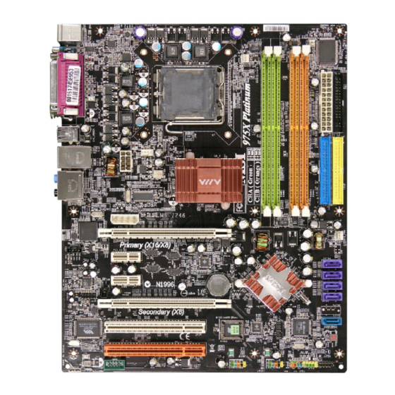
Page 15: Mainboard Layout
M S-7246 M ainboard Mainboard Layout JCI1 Top : mouse Bottom: keyboard SYSFAN1 Winbond W83627DHG Top : Parallel Port Bottom: COM A 1394 Port SPDIF USB ports CPUFAN1 T: LAN jack Intel B: USB ports 975X NB_FAN1 Line-I n Line-O ut T:RS -Out M:C S - Out... -
Page 16: Packing Checklist
Getting Started Packing Checklist MSI Driver/Utility CD SATA Cable MSI motherboard Standard Cable for Standard Cable for Power Cable Floppy Disk (Optional) IDE Devices D-Bracket 2 IEEE1394-Bracket Back IO Shield (Optional) (Optional) * The pictures are for reference only and may vary f rom the pac king c ontents of the product you User’s Guide... -
Page 17: Chapter 2 Hardware Setup
Chapter 2 Hardware Setup This chapter tells you how to install the CPU, memory modules, and expansion cards, as well as how to setup the jumpers on the mainboard. Also, it provides the instructions on connecting the peripheral devices, such as the mouse, keyboard, etc. -
Page 18: Quick Components Guide
M S-7246 M ainboard Quick Components Guide CPU, p.2-3 PWR_FAN, p2-14 CPU_FAN, p2-14 NB_FAN, p2-14 DIMM1/2/3/4, p.2-7 JPW, p.2-9 JCI1, p2-19 ATX, p.2-9 FDD, p.2-14 Back Panel, p.2-10 IDE1/IDE2, p.2-15 JPWR, p.2-9 PCIE_X16, SYS_FAN, p.2-24 p.2-14 JIR, p.2-17 JCD1, p.2-17 SATA1~4, PCIE_X1, p.2-16... -
Page 19: Cpu (Central Processing Unit)
W hen you are installing the CPU, make sure to install the cooler to prevent overheating. If you do not have the CPU cooler, contact your dealer to purchase and install them before turning on the computer. For the latest information about CPU, please visit http://www.msi.com.tw/pro- gram/products/mainboard/mbd/pro_mbd_cpu_support.php. Important 1. -
Page 20: Cpu & Cooler Installation
M S-7246 M ainboard CPU & Cooler Installation (CPU clip is optional) W hen you are installing the CPU, make sure the CPU has a cooler at- tached on the top to prevent overheating. If you do not have the cooler, contact your dealer to purchase and install them before turning on the computer. - Page 21 Hardware Setup 5. The CPU has a plastic cap on it to 6. Remove the cap from lever hinge side protect the contact from damage. (as the arrow shows). The pins of Before you have installed the CPU, socket reveal. always cover it to protect the socket pin.
- Page 22 M S-7246 M ainboard 12. Press down the load lever lightly 11. Visually inspect if the CPU is seated onto the load plate, and then secure well into the socket, then remove the the lever with the hook under reten- CPU Clip with 2 fingers.
-
Page 23: Memory
DDRII memory module in the DDRII slot. Otherwise, you are not able to boot up your system and your mainboard might be damaged. For the updated supporting memory modules, please visit http://www.msi. com.tw/program/products/mainboard/mbd/pro_mbd_trp_list.php. DIMM1~DIMM4 (from left (Greem) to right(Orange)) Channel A (DIMM1 &... -
Page 24: Installing Ddrii Modules
M S-7246 M ainboard GREEN ORANGE ORANGE GREEN DIMM1 (Ch A) DIMM2 (Ch A) DIMM3 (Ch B) DIMM4 (Ch B) System Density 256MB~2GB 256MB~2GB 512MB~4GB 256MB~2GB 256MB~2GB 512MB~4GB 256MB~2GB 256MB~2GB 512MB~4GB 256MB~2GB 256MB~2GB 512MB~4GB 256MB~2GB 256MB~2GB 256MB~2GB 256MB~2GB 1GB~8GB Important - Dual-channel DDRII works ONLY in the 5 combinations listed in the table shown in the previous page. -
Page 25: Power Supply
Hardware Setup Power Supply The mainboard supports ATX power supply for the power system. Before inserting the power supply connector, always make sure that all components are installed properly to ensure that no damage will be caused. ATX 24-Pin Power Connector: ATX This connector allows you to connect an ATX 24-pin power supply. -
Page 26: Ieee 1394 Port (Optional)
M S-7246 M ainboard Back Panel The back panel provides the following connectors: RS-Out L-In Parallel M ou se IEEE1394 SPDIF USB Ports Keyboard COM Port L-Out CS-Out (optional) SS-Out Mouse/Keyboard Connector ® The mainboard provides a standard PS/2 mouse/keyboard mini DIN connector ®... -
Page 27: Serial Port Connector: Com Port
Hardware Setup Serial Port Connector: COM Port The mainboard offers one 9-pin male DIN connector COM Port. It’s a 16550A high speed communication port that send/receive/ 16 bytes FIFOs. You can attach a serial mouse or other serial device directly to it. Pin Definition SIGNAL DESCRIPTION... -
Page 28: Lan (Rj-45) Jack
M S-7246 M ainboard LAN (RJ-45) Jack The mainboard provides 1 standard RJ-45 jack for connection to single Local Area Network (LAN). This LAN enables data to be transferred at 1000Mbps, 100Mbps or 10Mbps. You can connect a network cable to it. Giga-bit LAN Pin Definition SIGNAL DESCRIPTION... -
Page 29: Parallel Port Connector: Lpt1
Hardware Setup Parallel Port Connector: LPT1 The mainboard provides a 25-pin female centronic connector as LPT. A parallel port is a standard printer port that supports Enhanced Parallel Port (EPP) and Ex- tended Capabilities Parallel Port (ECP) mode. Pin Definition SIGNAL DESCRIPTION STROBE... -
Page 30: Floppy Disk Drive Connector: Fdd
M S-7246 M ainboard Connectors The mainboard provides connectors to connect to FDD, IDE HDD, case, LAN, and USB Ports. Floppy Disk Drive Connector: FDD The mainboard provides a standard floppy disk drive connector that supports 360K, 720K, 1.2M, 1.44M and 2.88M floppy disk types. F D D (black) Fan Power Connectors: CPU_FAN / SYS_FAN / PWR_FAN / NB_FAN... -
Page 31: Hard Disk Connector: Ide1/ Ide2
Hardware Setup Hard Disk Connector: IDE1/ IDE2 The mainboard supports 2 IDE connectors, which supports PIO & Bus Master operation modes. IDE1 (blue) IDE2 (yellow) IDE1 (Primary IDE Connector) The first hard drive should always be connected to IDE1. IDE1 can connect a Master and a Slave drive. -
Page 32: Sataii Connectors Controlled By Intel Ich7R: Sata1~Sata4
M S-7246 M ainboard SATAII Connectors controlled by Intel ICH7R: SATA1~SATA4 SATAII Connectors controlled by JMicron JMB361: SATA5 The SouthBridge of this mainboard is Intel ICH7R which supports four SATAII connectors (SATA1~SATA4). JMB361 of this mainboard supports another one SATAII connector (SATA5). -
Page 33: Front Panel Connectors: Jfp1 / Jfp2
Hardware Setup Front Panel Connectors: JFP1 / JFP2 The mainboard provides two front panel connectors for electrical connection ® to the front panel switches and LEDs. JFP1 is compliant with Intel Front Panel I/O Connectivity Design Guide. JFP1 Pin Definition SIGNAL DESCRIPTION Power... -
Page 34: Front Panel Audio Connector: Jaud1
M S-7246 M ainboard Front USB Connectors: JUSB1 / JUSB2 The mainboard provides two standard USB 2.0 pin headers JUSB1/ JUSB2. USB 2.0 technology increases data transfer rate up to a maximum throughput of 480Mbps, which is 40 times faster than USB 1.1, and is ideal for connecting high- speed USB interface peripherals such as USB HDD, digital cameras, MP3 players, printers, modems and the like. -
Page 35: Ieee 1394 Connector: J1394_1(Optional)
Hardware Setup IEEE 1394 Connector: J1394_1(Optional) The mainboard provides one 1394 pin header that allow you to connect op- tional IEEE 1394 port. Pin Definition SIGNAL SIGNAL TPA+ TPA- Ground Ground TPB+ TPB- J1394_1 Cable power Cable power Key (no pin) Ground How to attach the IEEE 1394 Port: Connected to J1394_1 (Green connector) -
Page 36: D-Bracket™ 2 Connector: Jled1
M S-7246 M ainboard D-Bracket™ 2 Connector: JLED1 The mainboard comes with a JLED1 connector for you to connect to D-Bracket™ 2. D-Bracket™ 2 is a USB Bracket that supports both USB1.1 & 2.0 spec. It integrates four LEDs and allows users to identify system problem through 16 various combina- tions of LED signals. - Page 37 Hardware Setup G reen Description D-Bracket™ 2 System Power ON The D-LED will hang here if the processor is damaged or not installed properly. Early Chipset Initialization Memory Detection Test Testing onboard memory size. The D-LED will hang if the memory module is damaged or not installed properly.
- Page 38 M S-7246 M ainboard D-Bracket™ 2 Description BIOS Sign On This will start showing information about logo, proces- sor brand name, etc... Testing Base and Extended Memory Testing base memory from 240K to 640K and extended memory above 1MB using various patterns. Assign Resources to all ISA.
-
Page 39: Clear Cmos Button: Sw
Hardware Setup Button The motherboard provides the following button for you to set the computer’s function. This section will explain how to change your motherboard’s function through the use of button. Clear CMOS Button: SW There is a CMOS RAM on board that has a power supply from external battery to keep the system configuration data. -
Page 40: Ati Crossfire (Multi-Gpu) Technology
M S-7246 M ainboard Slots The mainboard provides 2 PCI Express x16 slots, 2 PCI Express x1 slots and 2 PCI bus slots. It supports 2 PCIE x 16 slots transfer into 2 PCIE x 8 ports (CrossFire Technology). PCI Express Slots The PCI Express slots, as a high-bandwidth, low pin count, serial, intercon- nect technology, support Intel highest performance desktop platforms utilizing the Intel Pentium 4 processor with HT Technology. - Page 41 Hardware Setup 2.Use the external cable to connect the two graphics cards. The cable is attached from the CrossFire Ready graphics card’s DVI connector to the CrossFire Edition high density input connector (DMS). Then connectting a monitor to the left DVI connector.
- Page 42 M S-7246 M ainboard 3.When all of the hardware and software has been properly set up and installed, reboot the system. After enter to the O.S., click the “Catalyst™ Control Center” icon on the desktop. There is a setting in the Catalyst™ Control Center that needs to be enabled for CrossFire™...
-
Page 43: Pci (Peripheral Component Interconnect) Slots
Hardware Setup PCI (Peripheral Component Interconnect) Slots The PCI slots allow you to insert the expansion cards to meet your needs. W hen adding or removing expansion cards, make sure that you unplug the power supply first. Meanwhile, read the documentation for the expansion card to make any necessary hardware or software settings for the expansion card, such as jumpers, switches or BIOS configuration. -
Page 44: Chapter 3 Bios Setup
Chapter 3 BIOS Setup This chapter provides information on the BIOS Setup program and allows you to configure the system for optimum use. You may need to run the Setup program when: ² An error message appears on the screen during the system booting up, and requests you to run SETUP. -
Page 45: Entering Setup
M S-7246 M ainboard Entering Setup Power on the computer and the system will start POST (Power On Self Test) process. W hen the message below appears on the screen, press <DEL> key to enter Setup. Press DEL to enter SETUP If the message disappears before you respond and you still wish to enter Setup, restart the system by turning it OFF and On or pressing the RESET button. -
Page 46: Control Keys
BIOS Setup Control Keys <↑> Move to the previous item <↓> Move to the next item <←> Move to the item in the left hand <→> Move to the item in the right hand <Enter> Select the item <Esc> Jumps to the Exit menu or returns to the main menu from a submenu <+/PU>... -
Page 47: The Main Menu
M S-7246 M ainboard The Main Menu ® Once you enter Phoenix-Award BIOS CMOS Setup Utility, the Main Menu will appear on the screen. The Main Menu allows you to select from the eleven setup functions and two exit choices. Use arrow keys to select among the items and press <Enter> to accept or enter the sub-menu. - Page 48 BIOS Setup Load Fail-Safe Defaults Use this menu to load factory default settings into the BIOS for stable system per- formance operations. Load Optimized Defaults Use this menu to load the BIOS values for the best system performance, but the system stability may be affected.
-
Page 49: Standard Cmos Features
M S-7246 M ainboard Standard CMOS Features The items in Standard CMOS Features Menu includes some basic setup items. Use the arrow keys to highlight the item and then use the <PgUp> or <PgDn> keys to select the value you want in each item. Date (mm:dd:yy) This allows you to set the system to the date that you want (usually the current date). - Page 50 BIOS Setup Drive A This item allows you to set the type of floppy drive installed. Available options: [None], [360K, 5.25 in.], [1.2M, 5.25 in.], [720K, 3.5 in.], [1.44M, 3.5 in.], [2.88M, 3.5 in.]. Halt On The setting determines whether the system will stop if an error is detected at boot. Available options are: [All Errors] The system stops when any error is detected.
-
Page 51: Advanced Bios Features
M S-7246 M ainboard Advanced BIOS Features CPU Feature Press <Enter> to enter the sub-menu and the following screen appears: Intel(R) SpeedStep(tm) tech (EIST) The Intel SpeedStep technology allows you to set the performance level of the microprocessor whether the computer is running on battery or AC power. This field will appear after you installed the CPU which support speedstep technology. - Page 52 BIOS Setup Virtualization Technology W hen enabled, a VMM can utilize the additional hardware capabilities provided by vendor-pool technology. Setting options: [Enabled], [Disabled]. Hard Disk Boot Priority Press <Enter> to enter the sub-menu and the following screen appears: In the sub-menu, it shows the hard disks information that was installed in the system, and you can set the hard disk boot priority.
- Page 53 M S-7246 M ainboard Quick Boot Setting the item to [Enabled] allows the system to boot within 5 seconds since it will skip some check items. Setting options: [Enabled], [Disabled]. Boot Up NumLock LED This setting is to set the Num Lock status when the system is powered on. Setting to [On] will turn on the Num Lock key when the system is powered on.
-
Page 54: Advanced Chipset Features
BIOS Setup Advanced Chipset Features System BIOS Cacheable Selecting [Enabled] allows caching of the system BIOS ROM at F0000h-FFFFFh, resulting in better system performance. However, if any program writes to this memory area, a system error may result. Setting options: [Enabled], [Disabled]. Video BIOS Cacheable Selecting [Enabled] allows caching of the video BIOS ROM at C0000h to C7FFFh, resulting in better video performance. -
Page 55: Integrated Peripherals
M S-7246 M ainboard Integrated Peripherals USB Controller Select [Enabled] if your system contains a Universal Serial Bus (USB) controller and you have USB peripherals. Setting options: [Enabled], [Disabled]. USB 2.0 Controller Select [Enabled] if your system contains the USB 2.0 controller. Setting options: [Enabled], [Disabled]. - Page 56 BIOS Setup Onboard BCM GB LAN This field controls the onboard BCM GB LAN controller. Setting options: [Enabled], [Disabled]. PCI-E Compliancy Mode This field specify the PCI-E compliable mode. Setting options: [v1.0a], [v1.0]. IO Devices Configuration Press <Enter> to enter the sub-menu and the following screen appears: Onboard FDC Controller Select [Enabled] if your system has a floppy disk controller (FDC) installed on the system board and you wish to use it.
- Page 57 M S-7246 M ainboard ECP Mode Use DMA The ECP mode has to use the DMA channel, so choose the onboard parallel port with the ECP feature. After selecting it, the following message will appear: “ECP Mode Use DMA.” At this time, the user can choose between DMA channel [3] or [1].
- Page 58 BIOS Setup SATA Devices Configuration Press <Enter> to enter the sub-menu and the following screen appears: SATA Mode, On-Chip Serial ATA These 2 items allow you to select the SATA and the ATA/IDE configuration. For the setting options of SATA Mode, select [IDE] if you want to have SATA as IDE function.
-
Page 59: Power Management Setup
M S-7246 M ainboard Power Management Setup Important S3-related functions described in this section are available only when your BIOS supports S3 sleep mode. ACPI Function This item is to activate the ACPI (Advanced Configuration and Power Management Interface) Function. If your operating system is ACPI-aware, such as W indows 2000/ XP, select [Enabled]. - Page 60 BIOS Setup Suspend Time Out (M inute) If system activity is not detected for the length of time specified in this field, all devices except CPU will be shut off. Setting options: [Disabled], [1 Min], [2 Min], [4 Min], [8 Min], [10 Min], [20 Min], [30 Min], [40 Min], [1 Hour].
- Page 61 M S-7246 M ainboard Date (of M onth) Alarm The field specifies the date for Resume by RTC Alarm. Setting options: [0]~ [31]. Time (hh:mm:ss) Alarm The field specifies the time for Resume by RTC Alarm. Format is <hour> <minute><second>. POWER ON Function This controls how the PS/2 mouse or keyboard can power on the system.
-
Page 62: Pnp/Pci Configurations
BIOS Setup PNP/PCI Configurations This section describes configuring the PCI bus system and PnP (Plug & Play) feature. PCI, or Peripheral Component Interconnect, is a system which allows I/O devices to operate at speeds nearing the speed the CPU itself uses when communicating with its special components. - Page 63 M S-7246 M ainboard The setting must be set to Enabled if any ISA bus adapter in the system requires VGA palette snooping. INT Pin 1/2 Assignment The items let you assign an IRQ line to INT Pin#1~2 separately. Selecting Auto allows BIOS to determine the appropriate IRQ for each INT Pin.
-
Page 64: H/W Monitor
BIOS Setup H/W Monitor This section shows the status of your CPU, fan, overall system status, etc. Monitor function is available only if there is hardware monitoring mechanism onboard. Chassis Intrusion Detect The field enables or disables the feature of recording the chassis intrusion status and issuing a warning message if the chassis is once opened. -
Page 65: Cell Menu
Dynamic OverClocking Dynamic Overclocking Technology is the automatic overclocking function, included in ’s newly developed CoreCell the MSI Technology. It is designed to detect the load balance of CPU while running programs, and to adjust the best CPU frequency automatically. W hen the motherboard detects CPU is running programs, it will speed up CPU automatically to make the program run smoothly and faster. - Page 66 BIOS Setup Important Even though the Dynamic Overclocking Technology is more stable than manual overclocking, basically, it is still risky. We suggest user to make sure that your CPU can afford to overclocking regularly first. If you find the PC appears to be unstable or reboot incidentally, it's better to disable the Dynamic Overclocking or to lower the level of overclocking options.
- Page 67 M S-7246 M ainboard FSB & Memory Clock Ratio These settings control the ratio of FSB Clock and Memory Clock to enable the CPU & Memory to run at different frequency combinations. Please note that the setting options vary according to the CPU FSB Clock preset. Memory speed = FSB x Memory Ratio x Double Data Rate (ex.
- Page 68 BIOS Setup Important MSI Reminds You... The settings shown in different color in CPU Voltage, Memory Voltage and PCI Express Voltage help to verify if your setting is proper for your system. G ray: Default setting. Yellow: High performance setting.
-
Page 69: Cpu And Memory Clock Overclocking
M S-7246 M ainboard CPU and Memory Clock Overclocking The Dynamic OverClocking / FSB & Memory Clock Ratio/ Adjust CPU Ratio/ CPU FSB Frequency are the items for you to overclock the CPU and the Memory. Please refer to the descriptions of these fields for more information. Important 1. -
Page 70: Load Fail-Safe/Optimized Deafaults
BIOS Setup Load Fail-safe/Optimized Deafaults The two options on the main menu allow users to restore all of the BIOS settings to the default Fail-Safe or Optimized values. The Optimized Defaults are the default values set by the mainboard manufacturer specifically for optimal performance of the mainboard. -
Page 71: Bios Setting Password
M S-7246 M ainboard BIOS Setting Password W hen you select this function, a message as below will appear on the screen: Type the password, up to six characters in length, and press <Enter>. The password typed now will replace any previously set password from CMOS memory. You will be prompted to confirm the password. -
Page 72: Appendix A Introduction To Digicell
MP3 files management and communica- tion / 802.11g WLAN settings. Moreover, with this unique utility, you will be able to activate the MSI well-known features, Live Update and Core Center, which makes it easier to update the BIOS/drivers online, and to monitor the system hardware status (CPU/Fan temperature and speed) or to overclock the CPU/memory. -
Page 73: Activating Digicell
Activating DigiCell Once you have your DigiCell installed (locate the setup source file in the setup CD accompanying with your mainboard, path: Utility --> MSI Utility --> MSI DigiCell), it will have an icon in the system tray, a short cut icon on the desktop, and a short cut path in your “Start-up”... -
Page 74: Introduction
Introduction: Click on each icon appearing above to enter the sub-menu to make further configuration. M SI Click on this button to link to MSI website: http://www.msi.com.tw. Quick Guide Click on this button and the quick guide of DigiCell will be displayed for you to review. - Page 75 M S-7246 M ainboard Live Update You can take advantage of Live Update to detect and update BIOS and drivers online. Dual Core Center You can take advantage of Dual Core Center to monitor the health status of your mainboard/ graphics card, and to overclock under W indows OS if your system supports overclocking function.
-
Page 76: H/W Diagnostic
In the H/W Diagnostic sub-menu, you can see the information, status and note of each DigiCell. You may double check the connection and installation of the item marked as gray. You may also click on the Mail to MSI button to send your questions or suggestions to MSI’s technical support staff. -
Page 77: Communication
M S-7246 M ainboard Communication In the Communication sub-menu, you can see the status of all the LAN / W LAN / Bluetooth on the screen if the hardware is installed. The first icon indicates the onboard LAN on your system, the second icon indicates the wireless LAN status, and the third one is the information about the bluetooth on your system. -
Page 78: Software Access Point
Introduction to DigiCell Software Access Point In the Software Access Point sub-menu, you can see the communication status on your system and choose the desired software access point mode by clicking on the desired icon, in which the default settings are configured for your usage. The default software access point mode is set to WLAN Card M ode. -
Page 79: Access Point Mode
M S-7246 M ainboard Access Point Mode Click on “Setting” button of the Access Point Mode and the following screen will display. IP Sharing Click on this icon to enable/disable the IP sharing. The default of this setting is disabled. Disabled Enabled Enabling/disabling IP sharing depends on the different situation. -
Page 80: Wlan Card Mode
Introduction to DigiCell enable this feature, only PCs with MAC address located in Association Control List can connect to the wireless LAN. M AC Address MAC stands for Media Access Control. A MAC address is the hardware address of a device connected to a network. Security This option allows you to enable/disable the authentication function. -
Page 81: Live Update
BIOS/VGA Driver/Utility online so that you don’t need to search for the correct BIOS/driver version throughout the whole W eb site. To use the function, you need to install the “MSI Live Update 3” application. After the installation, the “MSI Live Update 3”... -
Page 82: Mega Stick
Introduction to DigiCell MEGA STICK In the MEGA STICK sub-menu, you can configure the settings of MSI MEGA STICK and the media files (*.m3u, *.mp3, *.wav, *.cda, *.wma) on your system. Basic Function Here you can edit your own play list with the buttons “load”, “save”, “delete”, “shuttle”, “repeat”... - Page 83 M S-7246 M ainboard There is also a toolbar for you to execute some basic function, like play, stop, pause, previous/next song, song info and volume adjust. There is also a scroll bar on the top for you to forward/rewind. pause next previous...
-
Page 84: Non-Unicode Programs Supported
Introduction to DigiCell Non-Unicode programs supported If you are using an operating system in European languages, and you’d like to play the media files in MEGA STICK with East-Asian languages (such as Chinese, Japanese... etc.), it is possible that the file names display incorrectly. However, you can ins tall the Supplemental Language Support provided by Microsoft to solve this problem. - Page 85 M S-7246 M ainboard 3. Then go to the [Advanced] tab and select the language you want to be supported (the language of the filename in the MegaStick) from the drop- down list in the [Language for non-Unicode programs], then click [Apply]. The system will install the necessary components from your Microsoft Setup CD immediately.
-
Page 86: Power On Agent
Introduction to DigiCell Power On Agent In the Power on Agent sub-menu, you can configure setting of power-on, power- off and restarting status. In the screen below, you can set the date, time, start-up programs respectively for power-on, power-off and restarting. Power On Here are the available settings for Power On function: Date... -
Page 87: Power Off / Restart
M S-7246 M ainboard Power Off / Restart You may configure the time (in the format hh:mm:ss) for the next power-off / restart. Start With Use the button “+Add” to add the start-up programs as DigiCell is activated next time. For example, you may like to have Outlook activated or a specified website linked when you get to the office every morning. -
Page 88: Auto Login
Introduction to DigiCell Auto Login Since the Power On function allows the system to power on automatically, you may have to enable this Auto Login function in the following situations: 1. If you are using a computer belonging to a domain in office, and you need to enter your user name &... -
Page 89: Appendix B Intel Ich7Hd Sata Raid
Appendix B Intel ICH7HD SATA RAID The optional southbridge ICH7DH provides a hybrid solution that combines four independent SATAII ports for support of up to four Serial ATAII (Serial ATAII RAID) drives. Serial ATAII (SATAII) is the latest generation of the ATA interface. -
Page 90: Using The Intel Matrix Stroage Manager Option Rom
M S-7246 M ainboard BIOS Configuration The Intel Matrix Storage Manager Option ROM should be integrated with the system BIOS on all motherboards with a supported Intel chipset. The Intel Matrix Stroage Manager Option ROM is the Intel RAID implementation and provides BIOS and DOS disk services. - Page 91 Intel ICH7HD SATA RAID After pressing the <Ctrl> and <I> keys simultaneously, the following window will appear: (1) Create RAID Volume Select option 1 “Create RAID Volume” and press <Enter> key. The following screen appears. Then in the Name field, specify a RAID Volume name and then press the <TAB>...
- Page 92 M S-7246 M ainboard In the Disk field, press <Enter> key and the following screen appears. Use <Space> key to select the disks you want to create for the RAID volume, then click <Enter> key to finish selection. Then select the strip value for the RAID array by using the “upper arrow” or “down arrow”...
- Page 93 Intel ICH7HD SATA RAID Important Since you want to create two volumes (Intel Matrix RAID Technology), this default size (maximum) needs to be reduced. Type in a new size for the first volume. As an example: if you want the first volume to span the first half of the two disks, re-type the size to be half of what is shown by default.
- Page 94 M S-7246 M ainboard (2) Delete RAID Volume Here you can delete the RAID volume, but please be noted that all data on RAID drives will be lost. Important If your system currently boots to RAID and you delete the RAID volume in the Intel RAID Option ROM, your system will become unbootable.
- Page 95 Intel ICH7HD SATA RAID (3) Reset Disks to Non-RAID Select option 3 Reset Disks to Non-RAID and press <Enter> to delete the RAID volume and remove any RAID structures from the drives. The following screen appears: Press <Y> key to accept the selection. Important 1.
-
Page 96: Installing Software
2. W hen the W indows XP Setup window is generated, press S to specify an Additional Device(s). 3. Copy all contents in the path \IDE\Intel\ICH7DH\Floppy on the MSI CD to a formatted floppy diskette to make a RAID driver floppy diskette. -
Page 97: Installation Of Intel Matrix Stroage Console
For this reason, you cannot remove or un-install this driver from the system after installation; however, you will have the ability to un-install all other non-driver components. Insert the MSI CD and click on the Intel IAA RAID Edition to install the software. Click on this item... - Page 98 M S-7246 M ainboard The InstallShield Wizard will begin automatically for installation showed as following: Click on the Next button to proceed the installation in the welcoming window. B-10...
- Page 99 Intel ICH7HD SATA RAID The window shows the components to be installed. Click Next button to continue. After reading the license agreement in the following window, click Yes button to continue. B-11...
- Page 100 M S-7246 M ainboard Select the folder in which you want the program to be installed in the following window, and click Next button to start installation. Select a program folder in the following window where you want Setup to add the program icon.
- Page 101 Intel ICH7HD SATA RAID The following window appears to show the Intel Application Accelerator RAID Edition Setup installation status. Once the installation is complete, the following window appears. B-13...
-
Page 102: Raid Migration Instructions
M S-7246 M ainboard RAID Migration Instructions The Intel Matrix Storage Console offers the flexibility to upgrade from a single Serial ATA (SATA) hard drive to RAID configuration when an additional SATA hard drive is added to the system. This process will create a new RAID volume from an existing disk. -
Page 103: Create Raid Volume From Existing Disk
Intel ICH7HD SATA RAID Create RAID Volume from Existing Disk To create a RAID volume from an existing disk, choose Action --> Create RAID Volume from Existing Hard Drive. The Create RAID Volume from Existing Hard Drive Wizard pops up to lead you for the following procedure. - Page 104 M S-7246 M ainboard (1) Step 1: Configure Volume Here you can configure the new RAID volume by entering the volume name, selecting the RAID level and strip size. † RAID Volume Name: A desired RAID volume name needs to be typed in where the ‘RAID_Volume0’ text currently appears above.
- Page 105 Intel ICH7HD SATA RAID 4KB: For specialized usage models requiring 4KB strips 8KB: For specialized usage models requiring 8KB strips 16KB: Best for sequential transfers 32KB: Good for sequential transfers 64KB: Good general purpose strip size 128KB: Best performance for most desktops and workstations (2) Select the source disk Then select the source disk that you wish to use and then click “--->”...
- Page 106 M S-7246 M ainboard (3) Select Member Hard Drive(s) Then select the member disk (the target disk) that you wish to use and then click “--->” to move it to the Selected field. Then click Next to continue. Please note that the existing data on the selected hard drive(s) will be deleted permanently.
- Page 107 Intel ICH7HD SATA RAID (4) Specify Volume Size Specify the amount of available array space to be used by the new RAID volume. You may enter the amount in the space or use the slider to specify. It is recommended you use 100% of the available space for the optimized usage. For RAID 0 volume, if you do not specify 100% of the hard drive space, the rest hard drive space will be worked as RAID 1 volume, which is the new technology called Intel Matrix RAID.
- Page 108 M S-7246 M ainboard (6) Start Migration The migration process may take up to two hours to complete depending on the size of the disks being used and the strip size selected. A dialogue window will appear stating that the migration process may take considerable time to complete, meanwhile a popup dialogue at the taskbar will also show the migration status.
-
Page 109: Degraded Raid Array
Intel ICH7HD SATA RAID Degraded RAID Array A RAID 1 or RAID 10 volume is reported as degraded when one of its hard drive members fails or istemporarily disconnected, and data mirroring is lost. As a result, the system can only utilize the remaining functional hard drive member. To re- establish data mirroring and restore data redundancy, refer to the procedure below that corresponds to the current situation. - Page 110 M S-7246 M ainboard 5. Exit Intel RAID Option ROM, and then reboot to W indows system. 6. W hen prompted to rebuild the RAID volume, click 'Yes'. 7.The Intel(R) Storage Utility will be launched. Right-click the new hard drive and select 'Rebuild to this Disk'.
-
Page 111: Appendix C. Jmicron Raid Introduction
Appendix C JMicron RAID Introduction JMicron’s RAID provides Serial ATA RAID 0 (Striping) , RAID 1 (Mirroring) and JBOD functionality to enhance the industry’s leading PCI Express-to-SATAII & PATA host controller products. Two major challenges facing the storage industry today are (1): keeping pace with the increasing performance demands of computer systems by improving disk I/O throughput, and (2): providing data accessibility in the face of hard disk failures while... -
Page 112: Raid - Redundant Array Of Independent Disks
M S-7246 M ainboard Introduction RAID - Redundant Array of Independent Disks RAID technology manages multiple disk drives to enhance I/O performance and pro- vide redundancy in order to withstand the failure of any individual member, without loss of data. RAID provides two RAID Set types, Striping (RAID 0) and Mirroring (RAID RAID 0 (Striping) Striping is a performance-oriented, non-redundant data mapping technique. -
Page 113: Creating And Deleting Raid Sets With Bios Utility
JMicron RAID Creating and Deleting RAID sets with BIOS Utility Be sure to set RAID mode for the Onboard JMB361 Mode of Integrated Periph- erals in BIOS before configuring the JMicron BIOS utility. After that press F10 to save the configuration and exit. During boot up (POST), press CTRL+J to enter the JMicorn BIOS RAID utility. -
Page 114: Creating Raid Set
M S-7246 M ainboard Creating RAID set 1. Select “Create RAID Disk Drive”. Then press <Enter>. 2. Then in the Name field, specify a RAID set name and then press the <Enter> to go to the next field. 3. Choose a 0-Striped, a 1-Mirror, or a JBOD-Concatenate combination set and then press <Enter>... - Page 115 JMicron RAID 4. In the Hard Disk Disk List menu, use <Space> key to select the disks you want to create for the RAID set, then click <Enter> key to finish selection. 5. Then select the strip value for the RAID array by using the “upper arrow” or “down arrow”...
- Page 116 M S-7246 M ainboard 6. Then select the capacity of the RAID set in the Size field. The default value is the maximum capacity of the selected disks. Then press <Enter> to the Confirm Creation field. 7. The Creation field will display a message to ask you to confirm the creation. Then press <Y>...
-
Page 117: Deleting Raid Set
JMicron RAID Deleting RAID set 1. Select “Delete RAID Disk Drive”. Then press <Enter>. 2. In the RAID Disk Driver List menu, use <Space> key to select the RAID set you want to delete. Then press <Del> key. 3. Press “Y” to accept the deletion when a deletion message is appeared. -
Page 118: Revert Hdd To Non-Raid
M S-7246 M ainboard Revert HDD to non-RAID Select Revert HDD to non-RAID and press <Enter>. In the Hard Disk Driver List menu use <Space> key to select the disks you want to revert then click <Enter> key. The following screen appears, press <Y> key to remove any RAID structures from the drives. -
Page 119: Install Driver In Windows Xp / 2000
You may make the Serial ATA RAID driver by yourself by following the instruction below. 1. Insert the MSI CD into the CD-ROM drive. 2. Click the “Browse CD” botton on the Setup Screen. 3. Copy all the contents in the \\IDE \ JM icron \ Floppy to a formatted floppy disk. -
Page 120: Viewing Raid Array Configurations
M S-7246 M ainboard JMicron Raid Configurer There is an application called JMicron Raid Configurer which helps you perform the following tasks of nVDIA RAID. • Viewing RAID Array Configurations View an array configuration (mirrored, striped) • Creating RAID Arrays •... -
Page 121: Creating Raid
JMicron RAID Creating RAID JMRaidTool supports the creation of RAID 0 and 1. 1. Left-click the “New Disk Array” button. 2. A wizard dialogue will display on the screen, following the description of every step to complete the creation. Deleting RAID 1. -
Page 122: Appendix D Realtek Alc882M Audio
Realtek ALC882M Audio Appendix D Realtek ALC882M Audio The Realtek ALC882M provides 10-channel DAC that simultaneously supports 7.1 sound playback and 2 chan- nels of independent s tereo s ound output (multiple streaming) through the Front-Out-Left and Front-Out- Right channels. It also provides Dolby Master Studio to bring you a new class of audio entertainment experi- ence by using home PCs. -
Page 123: Installation For Windows 2000/Xp
M S-7246 M ainboard Installing the Realtek HD Audio Driver You need to install the driver for Realtek ALC882M codec to function properly before you can get access to 2-, 4-, 6-, 8- channel or Dolby audio operations. Follow the procedures described below to install the drivers for different operating systems. - Page 124 Realtek ALC882M Audio 3. Click Next to install the Realtek High Definition Audio Driver. Click here 4. Click Finish to restart the system. S el ec t t hi s option Click here...
-
Page 125: Software Configuration
M S-7246 M ainboard Software Configuration After installing the audio driver, you are able to use the 2-, 4-, 6- or 8- channel audio feature now. Click the audio icon from the system tray at the lower-right corner of the screen to activate the HD Audio Configuration. It is also available to enable the audio driver by clicking the Azalia HD Sound Effect M anager from the Control Panel. -
Page 126: Sound Effect
Realtek ALC882M Audio Sound Effect Here you can select a sound effect you like from the Environment list. Environment Simulation You will be able to enjoy different sound experience by pulling down the arrow, totally 23 kinds of sound effect will be shown for selection. Realtek HD Audio Sound Manager also provides five popular settings “Stone Corridor”, “Bathroom”, “Sewer pipe”, “Arena”... - Page 127 M S-7246 M ainboard Equalizer Selection Equalizer frees users from default settings; users may create their owned preferred settings by utilizing this tool. 10 bands of equalizer, ranging from 100Hz to 16KHz. Save Reset The settings are saved 10 bands of equalizer permanently for future would go back to the de- fault setting...
- Page 128 Realtek ALC882M Audio Frequently Used Equalizer Setting Realtek recognizes the needs that you might have. By leveraging our long experience at audio field, Realtek HD Audio Sound Manager provides you certain optimized equal- izer settings that are frequently used for your quick enjoyment. [How to Use It] Other than the buttons “Pop”...
-
Page 129: Mixer
M S-7246 M ainboard Mixer In the Mixer part, you may adjust the volumes of the rear and front panels individually. 1. Adjust Volume You can adjust the volume of the speakers that you pluged in front or rear panel by select the Realtek HD Audio rear output or Realtek HD Audio front output items. - Page 130 Realtek ALC882M Audio W hen you are playing the first audio source (for example: use W indows Media Player to play DVD/VCD), the output will be played from the rear panel, which is the default setting. Then you must to select the Realtek HD Audio front output from the scroll list first, and use a different program to play the second audio source (for example: use Winamp to play MP3 files).
- Page 131 M S-7246 M ainboard 3. Playback control Playback device Tool Mute This function is to let you freely decide which ports to output the sound. And this is essential when multi- streaming playback enabled. - Realtek HD Audio Rear Output - Realtek HD Audio Front Output M u te You may choose to mute single or multiple volume controls or to completely mute...
- Page 132 Realtek ALC882M Audio 4. Recording control Recording device Tool Mute -Back Line in/Mic, Front Lin in -Realtek HD Audio Digital Input M u te You may choose to mute single or multiple volume controls or to completely mute sound input. Tool - Show the following volume controls This is to let you freely decide which volume control items to be displayed.
-
Page 133: Audioio
M S-7246 M ainboard AudioIO In this tab, you can easily configure your multi-channel audio function and speakers. You can choose a desired multi-channel operation here. a. Headphone for the common headphone b. 2CH Speaker for Stereo-Speaker Output c. 4CH Speaker for 4-Speaker Output d. - Page 134 Realtek ALC882M Audio Correct M essage Assume to plug a headphone in the Green jack at back panel. The icon beside green jack become visible and the dialogue “connected device” pops up. Check the headphone, then click OK. As soon as OK is clicked, the icon beside green jack becomes “headphone”...
- Page 135 M S-7246 M ainboard Connector Settings Click to access connector settings. Disable front panel jack detection (option) Find no function on front panel jacks? Please check if front jacks on your system are so-called AC’97 jacks. If so, please check this item to disable front panel jack detection. Enable auto popup dialogue, when device has been plugged in Once this item checked, the dialog “Connected device”...
- Page 136 Realtek ALC882M Audio S/PDIF Short for Sony/Philips Digital Interface, a standard audio file transfer format. S/PDIF allows the transfer of digital audio signals from one device to another without having to be converted first to an analog format. Maintaining the viability of a digital signal prevents the quality of the signal from degrading when it is converted to analog.
- Page 137 M S-7246 M ainboard Test Speakers You can select the speaker by clicking it to test its functionality. The one you select will light up and make testing sound. If any speaker fails to make sound, then check whether the cable is inserted firmly to the connector or replace the bad speakers with good ones.
-
Page 138: Microphone
Realtek ALC882M Audio Microphone In this tab you may set the function of the microphone. Select the Noise Suppres- sion to remove the possible noise during recording, or select Acoustic Echo Cancelltion to cancel the acoustic echo druing recording. Acoustic Echo Cancelltion prevents playback sound from being recorded by mi- crophone together with your sound. -
Page 139: Bass Management Setting
M S-7246 M ainboard Bass Management setting In this tab you can either adjust volume of every single speaker, or reach better speaker balance by adjusting distance. Vol um e Each speaker volume can be individually adjusted to accommodate room placement and audio source, ranging from -10 dB to 10 dB. -
Page 140: Dolby
Realtek ALC882M Audio Dolby Dolby Master Studio means to bring you a new class of entertainment experience, by using home PCs. Dolby Master Studio contains 4 elements 1. Dolby Headphone 2. Dolby virtual Speaker 3. Dolby Pro Logic IIx 4. Dolby Digital Live How to Enable Dolby Effect For Dolby Headphone Dolby Headphone delivers realistic 5 channel listening experience over any pair of... -
Page 141: 3D Audio Demo
M S-7246 M ainboard 3D Audio Demo In this tab you may adjust your 3D positional audio before playing 3D audio applica- tions like gaming. You may also select different environment to choose the most suitable environment you like. D-20... -
Page 142: Information
Realtek ALC882M Audio Information In this tab it provides some information about this HD Audio Configuration utility, including Audio Driver Version, DirectX Version, Audio Controller & Audio Codec. You may also select the language of this utility by choosing from the Language list. Also there is a selection Show icon in system tray. -
Page 143: Hardware Setup
M S-7246 M ainboard Hardware Setup Connecting the Speakers W hen you have set the Multi-Channel Audio Function mode properly in the software utility, connect your speakers to the correct phone jacks in accordance with the setting in software utility. n 2-Channel M ode for Stereo-Speaker Output Refer to the following diagram and caption for the function of each phone jack on the back panel when 2-Channel Mode is selected. - Page 144 Realtek ALC882M Audio n 4-Channel M ode for 4-Speaker Output Back Panel Description: Connect two speakers to back panel’s Line Out connector and two speakers to the real-chan- nel Line Out connector. 4-Channel Analog Audio Output Line In Line Out (Front channels) Line Out (Rear channels) Line Out (Center and Subwoofer channel, but no functioning in this mode) Line Out (Side Surround channels, but no functioning in this mode)
- Page 145 M S-7246 M ainboard n 6-Channel M ode for 6-Speaker Output Description: Connect two speakers to back panel’s Line Out connector, two speakers to the rear-channel Line out connec tor and two s p e a k e r s t o t h e c e n t e r / subwoofer-channel Line Out connector.
- Page 146 Realtek ALC882M Audio n 8-Channel M ode for 8-Speaker Output Description: Connect two speakers to back panel’s Line Out connector, two speakers to the rear-channel Line out connector, two speak- ers to the center/subwoofer- channel Line Out connector and two speakers to the side-chan- nel Line Out connector.
-
Page 147: Appendix E Dual Core Center
Dual Core Center Dual CoreCenter, the most useful and powerful utility that MSI has spent muc h researc h and ef forts to develop, helps users to monitor or configure the hard- ware status of MSI Mainboard & MSI Graphics card in windows, such as CPU/GPU clock, voltage, fan speed and temperature. -
Page 148: Activating Dual Core Center
Activating Dual Core Center Once you have your Dual Core Center installed (locate the setup source file in the setup CD accompanying with your mainboard, path: Utility --> MSI Utility --> Dual Core Center), it will have an icon in the system tray, a short cut icon on the desktop, and a short cut path in your “Start-up”... -
Page 149: Introduction
Dual Core Center Main Before using this utility, we have to remind you: only when installing a MSI NX xxxx Diamond series or RX xxxx Diamond series graphics card can activate the full func- tion of this utility. If you install a graphics card of other brand, only hardware status of the MSI mainboard would be available. - Page 150 M S-7246 M ainboard AV/ Game/ Office/ Silence/ Cool MSI provides five common settings for different environments. The settings had been set to optimal values to reac h better performanc e in eac h environment. Click the button you need.
-
Page 151: Dot (Dynamic Overclocking
Dynamic Overclocking Technology is an automatic overclocking function, included in ’s newly developed Dual CoreCenter Technology. It is designed to detect the the MSI loading of CPU/ GPU while running programs, and to over-clock automatically. When the motherboard detects that the loading of CPU is exceed the default threshold for a time, it will speed up the CPU and fan automatically to make the system run smoother and faster. -
Page 152: Clock
M S-7246 M ainboard Clock In the Clock sub-menu, you can see clock status (including FSB/ CPU clock of mainboard and GPU/ memory clock of graphics card) of your system. And you can select desired value for overclocking. There will be several items for you to select for overclocking after you click button. -
Page 153: Voltage
Dual Core Center Voltage In the Voltage sub-menu, you can see voltage status (including Vcore, memory, GPU voltage... etc.) of your system, and you can select desired value for overclocking. It will show several items to select for overclocking after you click the button. -
Page 154: Fan Speed
M S-7246 M ainboard FAN Speed In the FAN Speed sub-menu, you can read fan status of your system. Select higher speed for better cooling effect. There are several sections for you to change the fan speed to a section after clicking button. -
Page 155: Temperature
Dual Core Center Temperature In the Temperature sub-menu, you can see temperature status of your system. On the underside, it shows the graphs of the temperatures. Only the curves of the item which the button is lit up with red color will be shown. -
Page 156: User Profile
M S-7246 M ainboard User Profile In the User Profile sub-menu, click the setting button that besides the user profile bar, and the next screen will appear. Here you can define the clock/ fan speed/ voltage by your need, click the button to choose a value quickly, or click the plus / minus sign button to... - Page 157 Dual Core Center Use the draw bar to set the max system temperature. W hen the system temperature exceeds the threshold you defined, the system will pop up a warning message and shut down the system. Use the draw bar to set the minimal fan speed. When the fan speed is lower than the threshold you defined, the system will pop up a warning message.
Need help?
Do you have a question about the 975X Platinum Series and is the answer not in the manual?
Questions and answers