Table of Contents
Advertisement
Quick Links
Advertisement
Table of Contents

Related Manuals for Ultra-tow 71514


Summary of Contents for Ultra-tow 71514
- Page 1 Fat Tire 2-Bike Carrier Owner’s Manual WARNING: Read carefully and understand all ASSEMBLY AND OPERATION INSTRUCTIONS before operating. Failure to follow the safety rules and other basic safety precautions may result in serious personal injury. Item #71514 READ & SAVE THESE INSTRUCTIONS...
- Page 2 ® Thank you very much for choosing an Ultra-Tow product! For future reference, please complete the owner’s record below: Serial Number/Lot Date Code: ________________________________ Purchase Date: ____________________________________________ Save the receipt, warranty, and this manual. It is important that you read the entire manual to become familiar with this product before you begin using it.
-
Page 3: Table Of Contents
Table of Contents Intended Use ............................4 Packaging Contents ..........................4 Technical Specifications ........................4 Important Safety Information ....................... 4 Specific Operation Warnings ....................... 5 Main Parts of Bike Carrier ........................6 Assembly Instructions .......................... 6 Before Each Use ..........................11 Operating Instructions ........................ -
Page 4: Intended Use
Intended Use The Ultra-Tow Fat Tire 2-Bike Carrier transports up to two bikes and is compatible with 2" hitch receivers. The weight capacity of this carrier is 200 lb. The carrier will fit almost any style of bike with tires up to 5” wide. The carrier folds flat when not in use. -
Page 5: Specific Operation Warnings
⚠WARNING This product can expose you to lead, which is known to the State of California to cause cancer and birth defects or other reproductive harm. ⚠CAUTION BIKE CARRIER USE AND CARE Do not force the bike carrier. Products are safer and do a better job when used in the manner for which they are designed. -
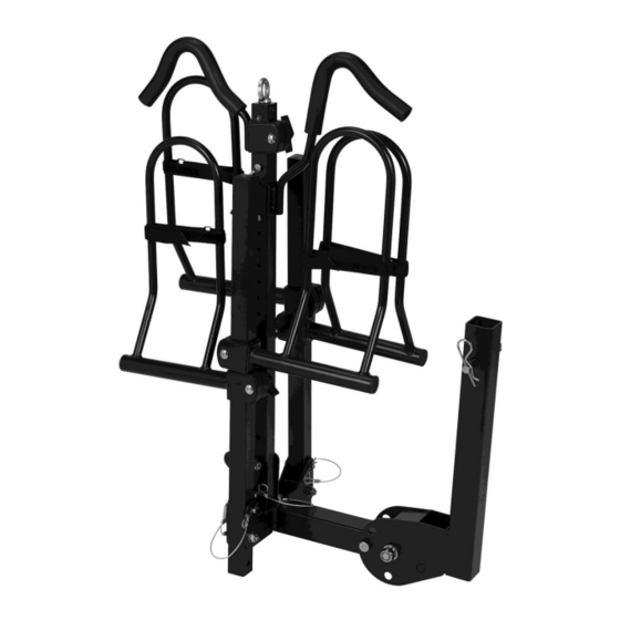
Page 6: Main Parts Of Bike Carrier
Main Parts of Bike Carrier Subassembly Support Base Assembly Vertical Arm Folding Shank Horizontal Arm Cradle Assembly Assembly Instructions Recommended Tools Monkey Wrench Open Wrench Open Wrench Size=300mm Size=17mm Size=24mm Page 6 of 17... - Page 7 1. Assemble the carrier frame by connecting the support base assembly (#1) and horizontal arm (#2) using an M10 carriage bolt (#4), L pin (#3), M10 flat washer (#5), and an M10 lock nut (#6). Turn the L pin (#3) 90 degrees to lock the horizontal arm (#2). See Figure 1. Figure 1 2.
- Page 8 3. Attach the folding shank (#8) to the support base assembly tube using an M16 bolt (#9), an M16 lock nut (#12), a 5/8 pin (#10), and a clip (#11) for extra safety. See Figure 3. " Figure 3 4. Slide the cradles onto the horizontal arms. Release the knob of the left and right cradle (#13 and #14).
- Page 9 5. Install the long J-hook assembly (#15) and short J-hook assembly (#16) onto the vertical arm. Tighten the eyebolt (#21). Secure the J-hooks by using a snap pin (#20). Place the reflector (#22) in the hole of the square tube. See Figure 5. Figure 5 6.
- Page 10 Mounting the Bikes The cradles and J-hooks are completely adjustable and slide onto the arms. Using the vertical knobs on the tops of the cradle and the horizontal knobs on the J-hooks. Twist until they are loose and the cradle or the J-hook can move on the tube. See Figures 7 and 8. Figure 7 Figure 8 Once adjusted, allow the bike to properly fit into the cradle.
-
Page 11: Before Each Use
Storage Feature Spin the L pin 90 degrees and then pull out from the center hole. Fold the main vertical arm to the horizontal position (down on the opposite side of folding shank) and re-secure using the L pin or by folding the horizontal arms upward. -
Page 12: Operating Instructions
Check that bike(s) are properly secured before beginning transport. Before each use, inspect bike rack for signs of wear, corrosion, and fatigue. Replace broken or worn parts before continuing use. Operating Instructions ⚠WARNING Do not exceed the rated load capacity of 200 lb. ... -
Page 13: Maintenance
Maintenance Maintain the bike carrier by adopting a program of conscientious repair and maintenance in accordance with the following recommended procedures. It is recommended that the general condition of any tool be examined before it is used. Keep your tool in good repair. Keep handles dry, clean, and free from oil and grease. -
Page 14: Parts Diagram
Parts Diagram Parts List Part# Description Quantity Part# Description Quantity Support Base Assembly M16 Lock Nut Horizontal Arm Left Cradle Assembly L Pin Right Cradle Assembly M10 Carriage Bolt Long J-hook Assembly M10 Flat Washer Short J-hook Assembly M10 Lock Nut Stabilizing Pin Vertical Arm 16 Spring Washer... -
Page 15: Replacement Parts
Replacement Parts For replacement parts and technical questions, please call Customer Service at 1-800-222-5381. Not all product components are available for replacement. The illustrations provided are a convenient reference to the location and position of parts in the assembly sequence. ... -
Page 16: Limited Warranty
Northern Tool and Equipment Company, Inc. ("We'' or "Us'') warrants to the original purchaser only ("You'' or "Your") that the Ultra-Tow product purchased will be free from material defects in both materials and workmanship, normal wear and tear excepted, for a period of one year from date of purchase. - Page 17 Distributed by: Northern Tool & Equipment Company, Inc. Burnsville, Minnesota 55306 www.northerntool.com Made in China Page 17 of 17...
Need help?
Do you have a question about the 71514 and is the answer not in the manual?
Questions and answers