
Related Manuals for GE Druck UPS-III


Summary of Contents for GE Druck UPS-III
- Page 1 Sensing Druck UPS-III Loop Calibrator User manual -K0317 0.561.8187 information@itm. www. .com...
-
Page 2: Approved Service Agents
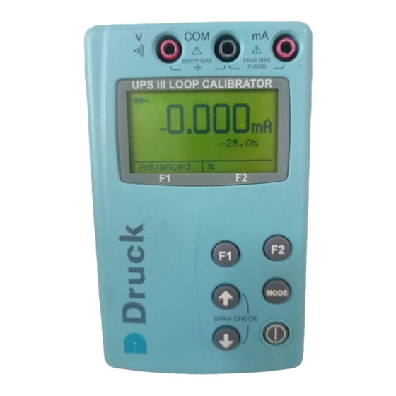
Approved Service Agents Symbols This equipment meets the requirements of all relevant European safety directives. The equipment carries the CE mark. This symbol, on the instrument, indicates that the user should refer to the user manual. Do not dispose of this product as household waste. - Page 3 UPS III Loop Calibrator Introduction The Druck UPS III Series of loop calibrators can supply power (source mode) and produce readings (measure mode) to perform field calibrations on 2-wire devices. The set-up menu enables the user to “source” or “measure” in either voltage or current and to perform continuity tests.
- Page 4 Physical Dimensions......77 x 129 x 24 mm(3” x 5” x 1”) Weight ..........275 grams (9.7 oz.) Terminals ........4 mm sockets {gold plated} Case ............High impact ABS Relative Humidity............ 0 to 90% Safety This symbol, on the loop calibrator, indicates that the user should refer to the user guide or manual.
- Page 5 OPERATION Keys key switches the calibrator on and off. Press and hold for 2 seconds. key changes the measure or source operating mode. Pressing the keys makes menu selections, sets numerical values and controls step and ramp functions (up/down). select advanced functions shown on the bottom of the display.
-
Page 6: Operating Modes
Operating Modes Pressing switches the instrument on and the display shows the start-up sequence. Pressing , at this time, the display shows the information screen: Information Serial number VERSION CAL. DATE HART BATTERY Pressing , at this time, the display shows the set-up screen: adjust Contrast adjust... - Page 7 Connect the loop calibrator to the device to be tested: Measure mA Press the mode key and select [Measure mA]. External power supplies Vmax = 60 V for the loop. The calibrator measures the current flow of the loop. Closed loop current measurement from transmitter test terminal.
- Page 8 Measure Volts Press mode key and select [Measure V], measure range 60V, maximum impedance 1 Mohm. Continuity Test Press mode key and select [Continuity Test]. Pressing switches the audible signal on/off. K0317 Issue No. 3 0.561.8187 information@itm. www. .com...
-
Page 9: Source Mode
Source Mode The display shows the source value in mA or % value of 4 to 20 mA or 0 to 20 mA, linear or flow depending on the settings made in set-up and advanced settings. Source mA Press mode key and select [Source mA]. The calibrator supplies maximum output of: 24 mA;... - Page 10 Advanced Options in a Source mode Press the key and select mA Source or mA Source & 24V. MODE (Enter) to select the function. Press the key (Advanced) and the display shows: Linear simulates linear transmitters. Flow simulates flow transmitters. Valve simulates valve control signals.
- Page 11 Operation of Advanced Options Press the key to switch the advanced setting on and off: e.g. on or off Press step the output up or down. step the span check maximum or minimum start the “ramp”. Press then to start: continuous auto-step.
-
Page 12: Maintenance
Maintenance • Return the loop calibrator to an authorised repair centre for any repairs, it cannot be repaired on-site. • To keep the loop calibrator accurate a calibration check should be carried out once per year. Cleaning • Clean the loop calibrator case with a moist, lint-free cloth and weak detergent. -
Page 13: Battery Replacement
Battery Replacement Only use the battery type listed on page one. Unscrew and remove the securing screw from the battery panel. Replace the batteries, check the polarity of the batteries. Refit and secure the battery panel. K0317 Issue No. 3 0.561.8187 information@itm. -
Page 14: Calibration Instructions
Calibration Instructions General The instrument is supplied by the manufacturer, complete with calibration certificate(s). A calibration period of 12 months is recommended. The actual calibration interval depends on instrument usage and the total measurement uncertainty acceptable for the specified application. The UPS-III is a very precise measuring instrument and the test equipment and conditions of test must be suitable for the type of work. -
Page 15: Calibration Check
Table 2 V measure Applied V Permitted UPS-III error Calibrator error (mV) (mV) 0.004 0.00040 0.004 0.00014 0.005 0.00064 0.005 0.00070 UPS-III source mode Table 3 mA source Applied Permitted UPS-III error Calibrator error (mA) (mA) 0.002 0.002 0.00012 0.002 0.00011 0.002 0.00015... -
Page 16: Calibration Adjustment
Calibration Adjustment 1.Connect the UPS-III to the electrical calibrator. Switch on the electrical calibrator and allow it to thermally stabilise. 2.Switch on the UPS-III and press , within two seconds to select Calibration. Enter the access code [9410 factory setting] and allow the instrument to thermally stabilise. 3.Select the parameter required for calibration. - Page 17 K0317 Issue No. 3 0.561.8187 information@itm. www. .com...
- Page 18 K0317 Issue No. 3 0.561.8187 information@itm. www. .com...
- Page 19 K0317 Issue No. 3 0.561.8187 information@itm. www. .com...
Need help?
Do you have a question about the Druck UPS-III and is the answer not in the manual?
Questions and answers