Table of Contents
Advertisement
Quick Links
The right choice for the ultimate yield!
LS ELECTRIC strives to maximize your profits in gratitude for choosing us as your partner.
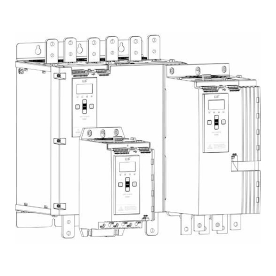
LSLV-SSM series
!
Safety Instructions
• Read this manual carefully before installing,
wiring, operating, servicing or inspecting this
equipment.
• Keep this manual within easy reach for quick
reference.
Soft Starter
Service Manual
Advertisement
Table of Contents

Subscribe to Our Youtube Channel
Related Manuals for LS ELECTRIC LSLV-SSM Series


Summary of Contents for LS ELECTRIC LSLV-SSM Series
- Page 1 The right choice for the ultimate yield! LS ELECTRIC strives to maximize your profits in gratitude for choosing us as your partner. Soft Starter Service Manual LSLV-SSM series Safety Instructions • Read this manual carefully before installing, wiring, operating, servicing or inspecting this equipment.
- Page 2 Product Identification This service manual applies to LS Electric SSMe and SSMi soft starters. Product description Soft starter name Basic model SSMe Advanced model SSMi Spare parts may vary depending on the soft starter model or rating. For the latest manuals and software, please visit our website.
-
Page 3: Table Of Contents
Contents About this manual ......................2 Caution statements ......................3 Identifying the serial number and version number ............4 Unit serial number and version ........................4 Date of manufacture ............................4 PCB serial number ............................4 Diagnostics ........................5 Power Circuit Test ............................5 Basic Functionality Test ..........................5 Review the Event Log ...........................5 Run Simulation Test ............................6... -
Page 4: About This Manual
About this manual Soft starter About this manual WARNING Indicates a hazard that may cause personal injury or death. CAUTION Indicates a hazard that may damage the equipment or installation. NOTE Provides helpful information. 2/38... -
Page 5: Caution Statements
Soft starter Caution statements Caution statements WARNING – ELECTRICAL SHOCK HAZARD The equipment contains dangerous voltages when connected to mains voltage. Only a qualified electrician should carry out the electrical installation. Improper installation of the motor or the soft starter may cause equipment failure, serious injury or death. Follow this manual and local electrical safety codes. -
Page 6: Identifying The Serial Number And Version Number
Identifying the serial number and version number Soft starter Identifying the serial number and version number Unit serial number and version The soft starter's serial number can be identified from the silver label on the starter. The soft starter version number is the last two digits of the first part of the serial number (xxxxVV-xxx). -0105B-V5-C1-H Serial number S/N: 123456-789... -
Page 7: Diagnostics
Soft starter Diagnostics Diagnostics NOTE The basic model controls the current across 1/L1-2/T1 and 5/L3-6/T3. When taking measurements across each phase, do not measure 3/L2-4/T2. NOTE Before changing any parameter settings, save the current parameter set to a file using WinMaster or the soft starter's Save User Set function (see the soft starter user manual for more information). -
Page 8: Run Simulation Test
Diagnostics Soft starter Run Simulation Test The run simulation simulates a motor starting, running and stopping, and can help identify faults within the soft starter. • If the starter does not respond to commands correctly, the user interface board may be faulty. •... -
Page 9: Start/Run Performance Test
Soft starter Diagnostics Start/Run Performance Test This procedure tests that the starter operates correctly during a soft start. Connect the starter to mains voltage, control voltage and to a motor. Set parameter 1B Motor Full Load Current to match the motor. Set parameter 2A Start Mode to 'Constant Current'. -
Page 10: Troubleshooting
Troubleshooting Soft starter Troubleshooting Trip messages Display Possible cause/Suggested solution 2 Phase - Damaged This message is displayed if the soft starter tripped on “Lx-Tx shorted” during the pre-start checks and PowerThrough is enabled. It indicates that the starter now operates in PowerThough mode (2-phase control only). - Page 11 Soft starter Troubleshooting Display Possible cause/Suggested solution Internal fault 88 The soft starter has detected a mismatch between its firmware and hardware. • The wrong firmware may be loaded in the starter. • The starter may not be detecting the hardware correctly. •...
-
Page 12: Scrs
Troubleshooting Soft starter SCRs SCR damage is generally caused by overcurrent, overvoltage or overtemperature. To prevent future damage, check that the soft starter has been installed properly. Common causes of SCR problems include: Overcurrent: • cable fault on soft starter output •... -
Page 13: Service Instructions
Soft starter Service instructions Service instructions Frame sizes The soft starters can be grouped into general layout configurations as follows: Frame Size Build Models configuration 0024B 0042B 0052B 0064B 0069B 0105B 0115B 0135B 0184B 0200B 0229B 0250B 0352B 0397B 0410B 0550B 0580B 0835B... - Page 14 Service instructions Soft starter 0024B~0042B 19782.A Cover Current transformers User interface board Expansion port cover Motor control board Internal bypass Upper skeleton SCRs Snubbers Heatsink Busbars Lower skeleton 12/38...
- Page 15 Soft starter Service instructions 0052B~0135B 19783.A Cover Expansion port cover User interface board Internal bypass Motor control board Upper skeleton SCRs Snubbers Heatsink Busbars Lower skeleton Current transformers 13/38...
- Page 16 Service instructions Soft starter 0184B ~ 0250B 19784.A Cover Expansion port cover User interface board Motor control board Air duct Upper skeleton SCRs Internal bypass Heatsink Snubbers (V7 models only) Lower skeleton Busbars End grille Current transformers 14/38...
- Page 17 Soft starter Service instructions 0352B ~ 0580B 19785.A Cover Expansion port cover User interface board Bypass driver board Motor control board Snubbers (V7 models only) Internal bypass Upper skeleton Phase arm Busbars Lower skeleton Current transformers End grille 15/38...
- Page 18 Service instructions Soft starter 0835B ~ 1250B 21951.A User interface board Cover Motor control board PCB support Bypass driver board PCB insulating sheet Busbars EMC and PCB support plate Bypass contactor Insulating sheet Phase arm Mounting foot Current transformers Expansion port cover Chassis Top cover Bottom cover...
- Page 19 Soft starter Service instructions 0735C~1220C 21952.A User interface board PCB insulating sheet Motor control board EMC and PCB support plate Bypass driver board Insulating sheet Busbars Mounting foot Phase arm Expansion port cover Current transformers Top cover Bottom cover Cover Chassis PCB support 17/38...
- Page 20 Service instructions Soft starter 0202E~1092E 23384.A User interface board PCB insulating sheet Motor control board PCB chassis Gate drive board Insulating sheet Phase arm Expansion port cover Current transformers Top cover Bottom cover Cover Chassis PCB support 18/38...
-
Page 21: Firmware Updates
Soft starter Firmware updates Firmware updates Overview The soft starter has two sets of operating firmware, run from microcontrollers on the motor control board and the user interface board. NOTE Boards sent as spare parts are not loaded with firmware. After replacing the motor control board and/or user interface board, firmware must be loaded into the starter. - Page 22 Firmware updates Soft starter Insert the memory stick into the starter's USB port. The starter will automatically load the new firmware. When the firmware has successfully loaded and verified, the starter will display a confirmation. Remove the memory stick. The starter will briefly display the message "Loading Language", followed by the welcome screen.
-
Page 23: Reusing Boards From Other Starters
Soft starter Firmware updates Reusing boards from other starters If you reuse a board that has previously been installed in another starter, you should update the firmware. Model name, model rating, serial number, parameter defaults The model rating is an internal reference, stored on both the motor control board and the user interface board. -
Page 24: Spare Parts
Spare parts Soft starter Spare parts NOTE Unless otherwise indicated, spare part kits contain only one of each item. All images in this section are indicative. Enclosure Opening Tools When dis-assembling the soft starter to perform repairs, use the recommended tools to open the enclosure. -
Page 25: User Interface Board
Soft starter Spare parts User interface board NOTE Boards sent as spare parts are not loaded with firmware. After replacing the motor control board and/or user interface board, firmware must be loaded into the starter. Each soft starter requires one user interface board. Different spare parts are required for C1 and C2 (mains or 24 V control voltage) models. - Page 26 Spare parts Soft starter 995-18605-00 24/38...
-
Page 27: Motor Control Board
Soft starter Spare parts Motor control board NOTE Boards sent as spare parts are not loaded with firmware. After replacing the motor control board and/or user interface board, firmware must be loaded into the starter. Each soft starter requires one motor control board. Different spare parts are required for V5 and V7 (mains voltage) models. - Page 28 Spare parts Soft starter 995-18607-00, 995-18608-00 995-18609-00, 995-18610-00 CAUTION Setting parameter 20D to a lower model may cause unreliable starting and stopping behaviour. Setting parameter 20D to a higher model can damage the soft starter. 26/38...
-
Page 29: Bypass Driver Board
Soft starter Spare parts Bypass driver board Some models include a bypass driver board. Each soft starter requires one bypass driver board. 0024B 0042B 0052B 0064B 0069B 0105B 0115B Not required 0135B 0184B 0200B 0229B 0250B 0352B 0397B 0410B 995-18611-00 0550B 0580B 0835B... -
Page 30: Gate Drive Board
Spare parts Soft starter Gate drive board Some models include a gate drive board. Each soft starter requires one gate drive board. 0024B 0042B 0052B 0064B 0069B 0105B 0115B Not required 0135B 0184B 0200B 0229B 0250B 0352B 0397B 0410B Not required 0550B 0580B 0835B... -
Page 31: Scrs
Soft starter Spare parts SCRs Models 0024B ~ 0250B use SCRs. Each kit contains one SCR. • Basic model: each soft starter requires two SCRs • Advanced model: each soft starter requires three SCRs 0024B 995-18612-00 0042B 995-18613-00 0052B 0064B 995-18614-00 0069B 0105B... -
Page 32: Phase Arms
Spare parts Soft starter Phase arms Models 0352B ~ 1250B/0735C ~ 1220C/0202E ~ 1092E use phase arms. Each kit contains one phase arm. • Basic model: each soft starter requires two phase arms • Advanced model: each soft starter requires three phase arms NOTE Phase arms for 0835B~1250B do not include a bypass contactor. -
Page 33: Fans
Soft starter Spare parts Fans Models 0052B ~ 1250B/0735C ~ 1220C require a fan. 0024B Not required 0042B 0052B 0064B 0069B 995-18622-00 0105B 0115B 0135B 0184B 0200B 0229B 0250B 0352B 995-18623-00 0397B 0410B 0550B 0580B 0835B 0940B 1070B 995-18623-00 1230B 1250B 0735C 0830C... -
Page 34: Current Transformers
Spare parts Soft starter Current transformers Each kit contains one current transformer. • Models 0024B ~ 0580B: each soft starter requires two current transformers • Models 0835B ~ 1250B/0735C ~ 1220C/0202E ~ 1092E: each soft starter requires three current transformers 0024B 0042B 0052B... - Page 35 Soft starter Spare parts 995-22310-00 33/38...
-
Page 36: 8.10 Internal Bypass Contactor
Spare parts Soft starter 8.10 Internal bypass contactor Each kit contains one internal bypass contactor. • Basic model: each soft starter requires two internal bypass contactors • Advanced model 0024B ~ 1250B: each soft starter requires three internal bypass contactors •... - Page 37 Soft starter Spare parts 995-18630-00 995-18631-00, 995-18632-00 995-22311-00 35/38...
-
Page 38: 8.11 Snubber Assemblies
Spare parts Soft starter 8.11 Snubber assemblies Each soft starter requires three snubber assemblies. Each snubber kit includes three snubber assemblies. NOTE Snubbers are not fitted as standard on 0024B ~ 0069B. Snubbers are available as a spare part if required for a particular installation. 0024B 0042B 0052B... - Page 39 Soft starter Spare parts 995-18636-00 995+-22312-00 37/38...
-
Page 40: Appendix
Appendix Soft starter Appendix Bolt Tightening Torques When assembling soft starter components, each bolt should be tightened using a calibrated torque driver set to the appropriate assembly torque. The following tables indicate the different types of bolts and bolt tightening torques for each assembly. SCRs to Heatsink Model Bolt size... - Page 41 E-Mail: ywyun@lselectricamerica.com Disclaimer of Liability LS ELECTRIC has reviewed the information in this publication to ensure consistency with the hardware and software described. However, LS ELECTRIC cannot guarantee full consistency, nor be responsible for any damages or compensation, since variance cannot be precluded entirely.
Need help?
Do you have a question about the LSLV-SSM Series and is the answer not in the manual?
Questions and answers