Table of Contents
Advertisement
Quick Links
Advertisement
Table of Contents

Subscribe to Our Youtube Channel
Related Manuals for Baxton Studio LCF20608C


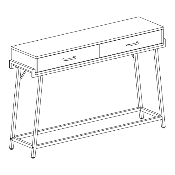
Summary of Contents for Baxton Studio LCF20608C
- Page 1 CONSOLE TABLE ASSEMBLY INSTRUCTION Date last updated: 6-21-2022...
- Page 2 HARDWARE LIST M6×35mm M7×38mm Ø15×12mm Ø7.8×30mm M4×35mm 250mm M3.5×14mm 106*Ø10*30mm M4×18mm M6×30mm M6×40mm M6×40mm M6×12mm PARTS LIST 1 - 1pc 2 - 1pc 3 - 1pc 4 - 1pc 5 - 1pc 6 - 1pc 7 - 1pc 8 - 1pc 9 - 2pcs 10 - 2pcs 11 - 2pcs...
- Page 3 ASSEMBLY STEPS Insert quickfit screws (A) into parts 7 and 8. Fix Handles (H) to parts 7 and 8 using screws (I), as shown. Insert cam locks (B) into parts 9 and 10, and attach parts 9 and 10 to parts 11 using screws (E), as shown.
- Page 4 Fix inner drawer runners (F2) to assembled drawers using screws (G), as shown. 250mm M3.5×14mm × × Fix outer drawer runners (F1) to parts 3, 4 and 6 using screws (G), as shown. 250mm M3.5×14mm × ×...
- Page 5 Insert quickfit screws (A) and wooden dowels (D) into part 1, as shown. M6×35mm Ø7.8×30mm × × Insert cam locks (B) into parts 4, 6 and 3, as shown. Fit parts 4, 6 and 3 to part 1. Turn cam lock clockwise to tighten, as shown. Slide part 5 into grooves between parts 4, 6, 3 and 1, as shown.
- Page 6 Insert wooden dowels (D) into parts 4, 6 and 3. Attach part 2 to assembled unit using screws (C) and allen key (N), as shown. M7×38mm Ø7.8×30mm × × × 1 Fix parts 16 to parts 14 and 15 using screws (L), as shown. Fix part 13 to parts 14 and 15 using screws (K), as shown.
- Page 7 Fix connecting brace 17 to assembled unit using screws (M), as shown. M6×12mm × Fix assembled unit to metal legs using screws (J), as shown. M6×30mm ×...
- Page 8 Fit drawers into assembled unit, as shown. For extra stability, it is recommended that you fix your console table to the wall using wall strap (R) and hardwares (O, P and Q), as shown. Fix wall strap (R) on to assembled unit using screw (Q), as shown. Screw (P) are fixed through wall strap and into the wall plugs (O).
Need help?
Do you have a question about the LCF20608C and is the answer not in the manual?
Questions and answers