Wilo DrainLift WS 40/50 Basic Installation And Operating Instructions Manual
Hide thumbs
Also See for DrainLift WS 40/50 Basic:
Table of Contents

Related Manuals for Wilo DrainLift WS 40/50 Basic


Summary of Contents for Wilo DrainLift WS 40/50 Basic
- Page 1 Pioneering for You Wilo-DrainLift WS 40/50 Basic de Einbau- und Betriebsanleitung Notice de montage et de mise en service en Installation and operating instructions Istruzioni di montaggio, uso e manutenzione · 6087354 • Ed.2020-07/05...
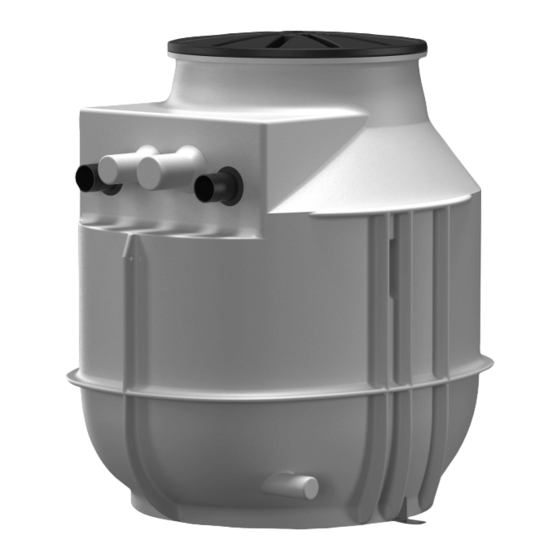
- Page 2 Fig.2.1: DrainLift WS 40E Basic Ø570 Ø63 100/75 Ø75 Ø50 Fig.2.2: DrainLift WS 40D Basic Ø570 Ø63 Ø75 100/75 Ø50 1000...
-
Page 3: Table Of Contents
During operation ...................................... 62 8 Shut-down/dismantling................................. 62 Personnel qualifications.................................... 62 Operator responsibilities.................................... 62 Shut-down........................................ 62 Clean and disinfect ...................................... 63 Pump removal........................................ 63 9 Maintenance and repair................................ 64 10 Spare parts.................................... 64 11 Faults, causes and remedies .............................. 64 WILO SE 05... -
Page 4: General Information
Distribute any content. ƒ Use any content for competition purposes without authorisation. Wilo shall reserve the right to change the listed data without notice and shall not be li- able for technical inaccuracies and/or omissions. Subject to change Wilo shall reserve the rights to make technical changes to the product and individual components. -
Page 5: Electrical Work
Select the lifting gear based on the prevailing conditions (weather, attachment point, load, etc.). ƒ Always attach the lifting gear to the attachment points. ƒ Ensure that the lifting gear is securely attached. ƒ Ensure that the hoisting gear is stable. WILO SE 05... -
Page 6: Installing/Dismantling
Use is not permitted for persons with limited physical, sensory or mental capacities! Application/use Intended use Pumping of sewage: ƒ In cases where sewage cannot be led to the sewer system via a natural fall. Installation and operating instructions Wilo-DrainLift WS 40/50 Basic... -
Page 7: Improper Use
Cleaning agents, disinfectants, dishwashing or laundry detergents in excess amounts, and such that have a disproportionately high degree of foam formation ƒ Drinking water Intended use also includes compliance with this manual. Any other use is regarded as non-compliant with intended use. WILO SE 05... -
Page 8: Product Description
The sewage produced is channelled into the pump chamber via the inlet, where it col- lects. When the water level reaches the switch-on level, the pump is switched on. The collected sewage is pumped into the on-site pressure pipe via the discharge pipe. When Installation and operating instructions Wilo-DrainLift WS 40/50 Basic... -
Page 9: Type Key
Defects must be noted on the freight documentation! Furthermore, de- fects must be notified to the transport company or the manufacturer immediately on the day of receipt of shipment. Subsequently notified defects can no longer be asser- ted. WILO SE 05... -
Page 10: Transport
The stability of the lifting equipment must be ensured during operation. ƒ When using lifting equipment, a second person must be present to coordinate the procedure if required (e.g. if the operator’s field of vision is blocked). Fig. 3: Attachment points Installation and operating instructions Wilo-DrainLift WS 40/50 Basic... -
Page 11: Storage
The operator is re- sponsible for the provision and suitability of the structural component/foundation! ƒ Demarcate the working area. ƒ Keep unauthorised persons away from the working area. ƒ Ensure free access to the installation location. WILO SE 05... -
Page 12: Installation
Ensure that the pump chamber does not become jammed during lifting and lower- ing. Do not exceed the maximum bearing capacity of the lifting equipment! Check that lifting equipment is functioning properly before use! Installation and operating instructions Wilo-DrainLift WS 40/50 Basic... - Page 13 Note on fixation material The lifting unit can be installed on various constructions (concrete, steel, etc.). Select the fixation material which is suitable for the relevant construction. For correct installa- tion, observe the following instructions for the fixation material: WILO SE 05...
- Page 14 Check the pump is properly fitted. ƒ ƒ Fit the chamber cover. Install the level control device. ƒ ƒ Final tasks. Lay the connection cable. ƒ Fit the chamber cover. ƒ Final tasks. Installation and operating instructions Wilo-DrainLift WS 40/50 Basic...
- Page 15 4. Place the pump chamber to one side. 5. Drill and clean the boreholes. 6. Insert the dowels (floor fixation) 7. Align the pump chamber with the boreholes. 8. Attach the pump chamber to the floor (floor fixation). WILO SE 05...
- Page 16 - Chamber cover flat to surface level ▶ Pump chamber installed. Next step: Connect the pressure pipe. 6.4.6 Connecting the pressure pipe DrainLift WS 40E/50E Basic DrainLift WS 40D/50D Basic Fig. 6: Pressure connection Installation and operating instructions Wilo-DrainLift WS 40/50 Basic...
- Page 17 CAUTION! Inlet surges or air intake into the pump chamber can cause the level control device to malfunction! ƒ Lay the inlet pipe with a slope to the pump chamber so that it can drain automatical- ƒ All connections must be completely tight! ƒ Install gate valve in the inlet! WILO SE 05...
- Page 18 The connection of an aeration and venting line is a specified requirement. Observe the following points when connecting the aeration and venting line: ƒ For building installation: Guide the aeration and venting line over the roof. ƒ All connections must be completely tight. Installation and operating instructions Wilo-DrainLift WS 40/50 Basic...
- Page 19 Shut off the inlet and drain the pump chamber. DrainLift WS 40E/50E Basic DrainLift WS 40D/50D Basic Fig. 10: Emergency drain connection Emergency drain connection Observe the following points when installing a diaphragm hand pump: WILO SE 05...
- Page 20 2. Screw the pump chamber extension onto the pump chamber. 3. Lock the pump chamber extension with the enclosed screw. Fig. 12: Fit the pump chamber extension - Make a 3 mm drilled hole approximately 50 mm (2 in) from the top of the pump Installation and operating instructions Wilo-DrainLift WS 40/50 Basic...
- Page 21 The level is measured in the following ways: Level measurement Pump ON/OFF • − − • − Float switch on the pump − • − − − Separate float switch − − • − • Level sensor High water alarm WILO SE 05...
- Page 22 The float switch is fitted to the pump. The cable length is already pre-set. If the pump is replaced, check the cable length and adjust it as specified. Fig. 14: Rexa MINI3: Float switch cable length Fig. 15: Rexa UNI: Float switch cable length Cable clip Clamp Cable Installation and operating instructions Wilo-DrainLift WS 40/50 Basic...
- Page 23 An explosive atmosphere can form within the pump chamber. If the cable bushing is not sealed airtight, the explosive atmosphere can spread into the operating space. There is a risk of fatal injury due to explosion! Make the cable bushing airtight. WILO SE 05...
- Page 24 3. Drill a 3 mm hole at the intended location in the chamber cover. Drill a hole through the cover and the pump chamber. 4. Screw in the enclosed screw. ▶ Chamber cover fitted and secured. Make the electrical connection. Installation and operating instructions Wilo-DrainLift WS 40/50 Basic...
-
Page 25: Electrical Connection
Make sure that the installation and operating instructions have been read and un- derstood by all personnel. ƒ All on-site safety devices are switched on and function properly. ƒ The pump chamber and the installed pump are suitable for use under the specified operating conditions. WILO SE 05... -
Page 26: Operation
The operation and functioning of the pumping station are known. ‡ Pressure pipe completely filled with water. 1. Activate the pumping station: - Insert the plug into the socket. - Switchgear: Switch on the main switch. Installation and operating instructions Wilo-DrainLift WS 40/50 Basic... -
Page 27: During Operation
▶ The pumping station is now out of operation. If the pumping station is out of operation for an extended period, carry out a functional check at regular intervals (quarterly). CAUTION! Carry out the functional check as de- scribed under “Test run”. WILO SE 05... -
Page 28: Clean And Disinfect
Improper conduct when carrying out electrical work can lead to death due to electric shock! Electrical work must be carried out by a qualified electrician in accordance with the locally applicable regulations. Installation and operating instructions Wilo-DrainLift WS 40/50 Basic... -
Page 29: Maintenance And Repair
Used protective clothing must be disposed off in accordance with the locally applicable guidelines. 12.2 Information on the collection of Proper disposal and appropriate recycling of this product prevents damage to the envi- used electrical and electronic ronment and putting your personal health at risk. products WILO SE 05...
Need help?
Do you have a question about the DrainLift WS 40/50 Basic and is the answer not in the manual?
Questions and answers