Table of Contents
Advertisement
Quick Links
DOCUMENT A-01-104-00
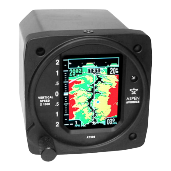
AT300 Hazard Awareness Display
AT300
AT300
AT300
Hazard Awareness Display
Hazard Awareness Display
Hazard Awareness Display
Operating Procedures
Operating Procedures
Operating Procedures
Operating Procedures
And
And
And
And
Installation Manual
Installation
Installation
Installation
Aspen Avionics
Aspen Avionics Document
Aspen Avionics
Aspen Avionics
Document Number:
Document
Document
PAGE 1/41
AT300 Operating Procedures and Installation Manual
AT300 Operating Procedures and Installation Manual
AT300 Operating Procedures and Installation Manual
AT300 Operating Procedures and Installation Manual
Manual
Manual
Manual
Number: A A A A - - - - 01
Number:
Number:
01- - - - 104
01
01
104- - - - 00
104
104
00
00
00
REVISION B
Advertisement
Table of Contents

Related Manuals for Aspen Avionics AT300


Summary of Contents for Aspen Avionics AT300
- Page 1 AT300 Operating Procedures and Installation Manual AT300 Operating Procedures and Installation Manual AT300 Operating Procedures and Installation Manual AT300 Operating Procedures and Installation Manual AT300 AT300 AT300 AT300 Hazard Awareness Display Hazard Awareness Display Hazard Awareness Display Hazard Awareness Display...
- Page 2 AT300 Operating Procedures and Installation Manual AT300 Operating Procedures and Installation Manual AT300 Operating Procedures and Installation Manual AT300 Operating Procedures and Installation Manual Document Revisions Document Revisions Document Revisions Document Revisions Revision Revision Description Description of Change of Change...
- Page 3 WARRANTY. If you require warranty service you may contact your local Aspen Authorized Dealer or you may contact Aspen Avionics directly. An original or copy of the sales receipt from the original Aspen Authorized dealer will be required to obtain any warranty service.
-
Page 4: Table Of Contents
AT300 Operating Procedures and Installation Manual AT300 Operating Procedures and Installation Manual AT300 Operating Procedures and Installation Manual AT300 Operating Procedures and Installation Manual Table of Contents Table of Contents Table of Contents Table of Contents 1 1 1 1 Introduction Introduction ........ - Page 5 Figure 15 - Crimping Tools ....................28 Figure 16 - Connector Housing Assembly................28 Figure 17 - Connector Pin Numbers ..................29 Figure 18 – AT300 Main Connector Pin-out ................29 Figure 19 - Commonly Used Pins.................... 30 Figure 20 - Wiring Diagram ....................30 Figure 21 - Common GPS Serial Interface Connections............
-
Page 6: Applicability
(TFT LCD). As the AT300 provides additional functionality beyond that of the VSI, additional electrical interfaces are required. In addition to an RS232 serial input from a panel mount GPS system, the AT300 requires a single power input from the aircraft power system, and an associated ground connection... -
Page 7: Non-Tso Functions
To support this functionality, aircraft barometric altitude data is obtained by measuring ambient pressure via the aircraft static connection, and baro corrections are required to be manually entered through the systems user interface (UI). In addition, the AT300 provides a supplemental display of GPS navigation data, including presentation of the current waypoint and identifier, and the current navigation leg in the moving map display area. -
Page 8: Specifications
AT300 Operating Procedures and Installation Manual AT300 Operating Procedures and Installation Manual AT300 Operating Procedures and Installation Manual AT300 Operating Procedures and Installation Manual 2 2 2 2 Specifications Specifications Specifications Specifications Physical Specifications Physical Specifications Physical Specifications Physical Specifications... -
Page 9: General System Operation General System Operation
AT300 Operating Procedures and Installation Manual AT300 Operating Procedures and Installation Manual AT300 Operating Procedures and Installation Manual AT300 Operating Procedures and Installation Manual 3 3 3 3 General System General System Operation Operation General System General System Operation Operation... -
Page 10: Cursor Control
Editing the Baro Setting Editing the Baro Setting The AT300 uses internally computed barometric altitude to render terrain and obstacles in the appropriate colors. To ensure correct terrain presentation, the baro setting must to be set to the correct and current baro value. - Page 11 WARNING WARNING WARNING Failure to set the correct baro setting on the AT300 will Failure to set the correct baro setting on the AT300 will Failure to set the correct baro setting on the AT300 will Failure to set the correct baro setting on the AT300 will...
-
Page 12: Terrain Presentation
The following colors are used to render the AT300 terrain map based upon the approximate proximity of terrain to the current aircraft baro corrected altitude. -
Page 13: Cold Temperature Operations
When on the ground, or during the landing or departure phases of flight, the AT300 will only render terrain that is more than 100’ above the aircraft’s current baro-corrected altitude. Any terrain that is less than 100’... -
Page 14: Vertical Speed Display
Extreme caution should be exercised whenever flight operations are conducted in cold temperatures to ensure that adequate terrain clearance exists. The AT300 is not acceptable for use as the sole means of determining the aircraft’s terrain separation. WARNING WARNING... -
Page 15: Rising Terrain Bar
A digital VSI value is also provide by the AT300, presented in a dedicated display field located near the bottom and immediately adjacent to the VSI tape. -
Page 16: Height Above Ground Digital Indication
This digital AGL value is presented in a dedicated text field in the lower right hand corner of the AT300 display area. This indicator shows the aircraft height above ground to the nearest 100 fpm, using two digits. -
Page 17: Airport Locations
Obstructions Obstructions Obstructions The AT300 obstruction data base includes all man made towers in the coverage area with an elevation of 250’ above ground level or higher. The obstructions are depicted using a color coded triangle icon depicted below. Figure... -
Page 18: System Status Messages
3.12 System Status Messages System Status Messages 3.12 3.12 System Status Messages System Status Messages The following system status messages may be annunciated by the AT300 in a text block in the middle of the moving map display area Message/Indication Message/Indication Message/Indication Message/Indication... -
Page 19: Database Updating
AT300 Operating Procedures and Installation Manual AT300 Operating Procedures and Installation Manual AT300 Operating Procedures and Installation Manual AT300 Operating Procedures and Installation Manual 3.13 3.13 3.13 3.13 Database Updating Database Updating Database Updating Database Updating Terrain, airports and obstructions are updated by removing the database label and associated data card located on the side of the unit. -
Page 20: Equipment Description
Navigation information from the connected GPS system can also be presented in the AT300 moving map area. In addition to an RS232 serial input from a panel mount GPS system, the AT300 requires a single power input from... -
Page 21: Tso Installation Statement
Limitations When installed in accordance with this installation manual and the limitations that follow, the installation of the AT300 is unlikely to have an appreciable effect on the weight, balance, structural strength, reliability, operational characteristics, or other characteristics affecting the airworthiness of the aircraft, and should therefore be eligible for installation as a minor alteration. - Page 22 The installation decision flow charts that follow are provided as an aid to the installer for ascertaining the eligibility of the AT300 for use in 14 CFR part 23 classes I, II and III aircraft operated under 14 CFR part 91 or part 135 operating rules.
- Page 23 AT300 Operating Procedures and Installation Manual AT300 Operating Procedures and Installation Manual AT300 Operating Procedures and Installation Manual AT300 Operating Procedures and Installation Manual AT300 Installation Limitations - Sheet 1 Start Is installation into a part 23 Go to Sheet 2...
- Page 24 AT300 Operating Procedures and Installation Manual AT300 Operating Procedures and Installation Manual AT300 Operating Procedures and Installation Manual AT300 Operating Procedures and Installation Manual AT300 Installation Limitations - Sheet 2 From Sheet 1 Installation specific evaluation is required to determine if the aircraft...
-
Page 25: Installation Steps (Summary)
Mounting Location Mounting Location Mounting Location Mounting Location The AT300 is optically optimized to be located within the pilots primary field of view, in the lower right position of the standard “T” configuration: Preferred AT300 Installation Location Figure Figure... -
Page 26: Optimal Viewing Angle
Mounting Method Mounting Method Three (3) #6 screws are provided in the AT300 installation kit and should be used to mount the AT300. The screws must be at least ¾” (thread length), and no more than 1½” long. Standard instrument “Black Coated” brass screws are preferred. -
Page 27: Electrical Connections
4.11.1 4.11.1 Load Analysis Load Analysis Ensure that an electrical load analysis is performed to verify that the additional load introduced by the AT300 is within the design parameters of the aircrafts electrical system. 4.11.2 4.11.2 4.11.2 4.11.2 Installation Connector Kit... - Page 28 AT300 Operating Procedures and Installation Manual AT300 Operating Procedures and Installation Manual AT300 Operating Procedures and Installation Manual AT300 Operating Procedures and Installation Manual MIL/SPEC: M22520/2-01 or POSITRONICS: 9507 or DANIELS: AFM8 or equivalent. (Ensure correct turret head is used)
- Page 29 17 - - - - Connector Pin Numbers Connector Pin Numbers Connector Pin Numbers Connector Pin Numbers The above figure shows the connector pin numbering of the AT300 unit, as as as viewed from the rear of the viewed from the rear of the viewed from the rear of the viewed from the rear of the unit.
- Page 30 Connection Connection Connection A single power line must be supplied to the AT300 from the aircraft avionics power bus. The AT300 does not incorporate a separate power switch, and is powered-on in conjunction with the other non-switched avionics systems. DOCUMENT A-01-104-00...
- Page 31 GPS Interface Connection Serial (RS-232) data is provided from the panel mounted GPS navigator to the AT300. This is a single wire interface that uses aircraft ground as a reference. A single conductor, shielded wire is used for this interface.
- Page 32 AT300 Operating Procedures and Installation Manual AT300 Operating Procedures and Installation Manual AT300 Operating Procedures and Installation Manual AT300 Operating Procedures and Installation Manual The following table defines some common GPS unit interface connections: Unit Unit Connector Connector Serial Output Pin...
-
Page 33: Post Installation Checkout
1. Apply power to the unit while holding the unit knob in the depressed position. 2. Release the knob prior to completion of the startup sequence. 3. Upon completion of the start up self tests, the AT300 will enter the Data Monitor Mode and will display the page shown below. -
Page 34: Interface Verification
Demo Mode Function Demo Mode Function Demo Mode Function Each AT300 includes a built in demonstration mode where the unit displays a short flight profile sequence for demonstration purposes. During Demo mode operation “DEMO MODE” is continually displayed in yellow immediately below the current track field. - Page 35 AT300 Operating Procedures and Installation Manual AT300 Operating Procedures and Installation Manual AT300 Operating Procedures and Installation Manual AT300 Operating Procedures and Installation Manual NOTE NOTE NOTE NOTE Once in Demo Mode, the unit will enter into Demo Mode Once in Demo Mode, the unit will enter into Demo Mode...
-
Page 36: Trouble Shooting Guide
AT300 Operating Procedures and Installation Manual AT300 Operating Procedures and Installation Manual AT300 Operating Procedures and Installation Manual AT300 Operating Procedures and Installation Manual Trouble Shooting Guide: Trouble Shooting Guide: Trouble Shooting Guide: Trouble Shooting Guide: Symptom Symptom Verify Verify... -
Page 37: Continued Airworthiness
Aspen Avionics will release updates to the unit databases approximately every six months. The AT300 database is updated by removing the database label and associated data card located on the side of the unit. Procedures to complete this activity will be supplied with the database update kit. - Page 38 AT300 Operating Procedures and Installation Manual AT300 Operating Procedures and Installation Manual AT300 Operating Procedures and Installation Manual AT300 Operating Procedures and Installation Manual 7 7 7 7 Environmental Qualification Form Environmental Qualification Form Environmental Qualification Form Environmental Qualification Form...
- Page 39 The following serial interface specification applies to the format of the RS-232 data transmitted from the GPS navigator to the AT300 GPS input port. Data is accepted in packets coded in the industry standard "avionics" format at a baud rate of 9600, 8 data bits, 1 stop bit, no parity. Packets are accepted at approximately 1 Hz.
- Page 40 AT300 Operating Procedures and Installation Manual AT300 Operating Procedures and Installation Manual AT300 Operating Procedures and Installation Manual AT300 Operating Procedures and Installation Manual 'w' messages are waypoint route information and correspond to the flight plan programmed in the GPS navigator. A unique 'w' message is allocated for each waypoint in the current flight plan. The following table describes the bit coding within the message value field.
- Page 41 Note to Dealer: Please complete the Above Warranty Registration Card, provide the original to the customer, retain one copy for your records, and mail one copy to Aspen Avionics at the address below. Failure to complete this warranty registration card and return it to Aspen Avionics may result in delays in obtaining warranty service.
Need help?
Do you have a question about the AT300 and is the answer not in the manual?
Questions and answers