Aspen Avionics EFD1000 Airplane Flight Manual Supplement
Hide thumbs
Also See for EFD1000:
- Pilot's manual (228 pages) ,
- Instruction manual (225 pages) ,
- Flight manual (41 pages)
Table of Contents
Advertisement
Quick Links
EFD1000 (Pilot) AIRPLANE FLIGHT MANUAL SUPPLEMENT
The information contained in this Supplement must be
attached to the FAA Approved Airplane Flight Manual when
the Aspen EFD1000 Electronic Flight Instrument System
PILOT MODEL is installed in accordance with AML STC
SA10822SC.
The information in this Supplement supplements or
supersedes the information in the FAA Approved Airplane
Flight Manual only as set forth herein.
For limitations, procedures, and performance data not
contained in this Supplement, consult the Airplane Flight
Manual.
Listed on Aspen EFD1000 Approved Model List (AML)
Listed on Aspen EFD1000 Approved Model List (AML)
DOCUMENT # A-01-179-00
FAA APPROVED
Date: March 17, 2008
EFD1000 (Pilot) Airplane Flight Manual Supplement
Aspen Avionics, Inc.
5001 Indian School NE
Albuquerque, NM 87110 USA
Document A-01-179-00 Revision A
FAA APPROVED
Airplane Make:
Airplane Model:
Airplane Registration Number:
Airplane Serial Number:
PAGE 1 OF 29
© Copyright 2008 Aspen Avionics Inc.
REVISION A
Advertisement
Table of Contents

Related Manuals for Aspen Avionics EFD1000


Summary of Contents for Aspen Avionics EFD1000
- Page 1 For limitations, procedures, and performance data not contained in this Supplement, consult the Airplane Flight Manual. Airplane Make: Listed on Aspen EFD1000 Approved Model List (AML) Airplane Model: Listed on Aspen EFD1000 Approved Model List (AML) Airplane Registration Number: Airplane Serial Number:...
- Page 2 EFD1000 (Pilot) Airplane Flight Manual Supplement Document Revisions Document Pages Description of Change Approval Revision Revised S. Frances Initial FAA APPROVED Release 1267 Original Prepared Release Authorization signatures on file. See ECO for release date and Reviewed Release Date: 3/3/08 dispositions.
-
Page 3: Table Of Contents
EFD1000 (Pilot) Airplane Flight Manual Supplement TABLE OF CONTENTS GENERAL ............................5 ........................5 YSTEM VERVIEW LIMITATIONS ............................6 ........................6 OFTWARE ERSIONS ........................6 IRSPEED IMITATIONS & C ................... 6 EIGHT ENTER OF RAVITY IMITS RSM GPS U ......................... 6 SAGE ....................... - Page 4 EFD1000 (Pilot) Airplane Flight Manual Supplement INTENTIONALLY LEFT BLANK DOCUMENT # A-01-179-00 PAGE 4 OF 29 REVISION A FAA APPROVED Date: March 17, 2008 © Copyright 2008 Aspen Avionics Inc.
-
Page 5: General
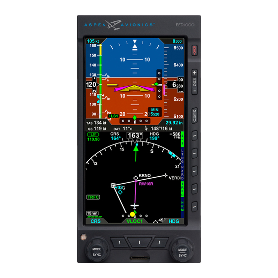
The EFD1000 “Pilot” system components include the EFD1000 display head, a Remote Sensor Module (RSM), and a Configuration Module (CM). The EFD1000 “Pilot” model does not support display of navigation data from panel-mounted GPS navigators, VOR/Localizer radios, etc., nor does it integrate with the aircraft autopilot system. -
Page 6: System Overview Limitations
The maximum approved operating airspeed for this system is 210 KTS (242 MPH). Weight & Center of Gravity Limits Installation of the EFD1000 system may result in a small net change to the aircraft empty weight and associated moment arm. Refer to the revised weight and balance records carried in the aircraft for details. -
Page 7: Placards And Decals
“RSM GPS REVERSION EMER USE ONLY” Seaplane Operation The EFD1000 system may not be able to align when on water as a function of the wave action being experienced by the aircraft. When aligning on water, always perform a visual verification of the attitude reference with a secondary source, such as a mechanical gyro or the horizon. -
Page 8: Emergency And Abnormal Procedures
“AHRS: RESET?” LINE SELECT KEY ...... PRESS “AHRS: RESET?” LINE SELECT KEY ...... PRESS AGAIN TO CONFIRM RESET NOTE: When the EFD1000 AHRS is reset in flight, it performs an abbreviated initialization. During the initialization, the aircraft should not be subjected to excessive turn rates. -
Page 9: Loss Of External Power
EFD1000 (Pilot) Airplane Flight Manual Supplement Loss of External Power In the event that external power to the unit fails, the EFD1000 will automatically switch to its internal battery. When operating on internal battery, the display backlight intensity is capped at a value of 70. -
Page 10: Warning, Caution, And Advisory Summary
RSM GPS mapping data is invalid or not available. RSM GPS Amber annunciation presented whenever REVERSION the EFD1000 reverts to RSM GPS data EMER USE and indicates that the RSM GPS is the ONLY current GPS source. RSM GPS usage is limited to “EMER USE ONLY”... -
Page 11: Normal Procedures
Before Taxi Checks EFIS MASTER (If installed) ..........ON Avionics and Instruments ..........SET as desired NOTE: The AHRS will perform an internal test during EFD1000 power up. The aircraft should remain stationary during the AHRS power up and alignment sequence. -
Page 12: Performance
EFD1000 (Pilot) Airplane Flight Manual Supplement Performance No change. DOCUMENT # A-01-179-00 PAGE 12 OF 29 REVISION A FAA APPROVED Date: March 17, 2008 © Copyright 2008 Aspen Avionics Inc. -
Page 13: System Description
EFIS Master Switch. Whenever indicated airspeed is invalid or below 30 KIAS the EFD1000 will power up and power down with the application or removal of external power. To turn on the system, turn on the aircraft Battery Master switch and, if installed, the optional EFIS Master switch. - Page 14 EFD1000 (Pilot) Airplane Flight Manual Supplement The EFD1000 internal battery will provide at least 30 minutes of power when it is fully charged. The battery provides power to the display head, RSM and emergency GPS. Reducing the backlight intensity will extend the battery operating time.
- Page 15 EFD1000 (Pilot) Airplane Flight Manual Supplement Display Screen and Control Layout 6.2.3 Reversion Control Range Control Menu Control “TPS” Tapes ON/OFF Control Not Used “360/ARC” HSI View Control “MAP” ON/OFF logic Control Not Used Right Control Knob Left Control Knob...
- Page 16 The home state for the right knob is “HDG.” Setting Flight Instruments 6.2.5 The following procedures are used to adjust pilot-editable data on the EFD1000: Heading Bug Set To set the heading bug, repeatedly PUSH the right control knob until the HDG field is enabled for editing.
- Page 17 EFD1000 (Pilot) Airplane Flight Manual Supplement Knob Sync Function 6.2.6 Editable fields may be synchronized as a function of data type as described in Table 1 below. Whenever a control knob is held for approximately one second the active data type will be “sync’d”...
- Page 18 Each successive push of the MAP hot key will turn the basemap on and off. In the Pilot model of the EFD1000, basemap consists of data associated with the active GPS flight plan The FP ONLY selection displays just the flight plan legs and waypoints associated with the GPS flight plan, and no other basemap features.
-
Page 19: Primary Flight Instruments
Map Range Control 6.2.9 The EFD1000 basemap range may be set to ranges of 2.5, 5, 10, 15, 20, 30, 40, 60, 80, 100, and 200 nautical miles. Map range is measured from the own ship position to the outside of the compass arc. - Page 20 EFD1000 (Pilot) Airplane Flight Manual Supplement Figure 7 - Attitude Indicator Pitch Markings The pitch scale consists of minor pitch marks in 2.5º increments up to ±20º and major pitch marks in 10º increments up to ±90º Roll Markings The roll scale is indicated by tick marks at 10º, 20º, 30º, 45º and 60º on both sides of the zero roll inverted solid white triangle.
- Page 21 EFD1000 (Pilot) Airplane Flight Manual Supplement During in-flight AHRS alignment the aircraft should be nominally operated in straight and level un-accelerated flight to ensure the quickest alignment times. Mild maneuvers up to 20 degrees of bank are permitted, however this may result in longer AHRS initialization times.
- Page 22 EFD1000 (Pilot) Airplane Flight Manual Supplement Band Band Description Color Range White White arc corresponding to the flap operating range extending from the full-flap stall speed ) up to the full flap extend speed (V <V Red arc extending from the bottom of the airspeed tape range up to full flap stall speed ).
- Page 23 EFD1000 (Pilot) Airplane Flight Manual Supplement Figure 11 - Airspeed Indicator Altimeter 6.3.4 Altitude is indicated by a moving altitude tape against a fixed position altitude pointer. A digital, rolling drum readout indicating altitude values to the closest 20 feet is provided adjacent to the fixed pointer.
- Page 24 EFD1000 (Pilot) Airplane Flight Manual Supplement After reaching the selected altitude if the aircraft altitude deviates by more than ±200 feet from the preselect value then a flashing yellow altitude deviation alert is generated, accompanied by a steady one-second tone from the optional aural alerter.
-
Page 25: Situational Awareness Map Display
Basemap The basemap presents map symbols for GPS flight plan waypoints. Basemap data is presented whenever the EFD1000 system is connected to a compatible GPS. Basemap symbols underlay all other instruments and annunciations in the lower half of the display. -
Page 26: Main Menu Operation
To select the Main Menu, press the MENU button on the right side of the display bezel. To leave the menu, press the MENU button again. Menu items are shown exclusively in the lower half of the EFD1000 display in the region below the data bar. DOCUMENT # A-01-179-00... - Page 27 EFD1000 (Pilot) Airplane Flight Manual Supplement Main Menu Navigation Once the Main menu is activated, rotating the lower right control knob selects between the various menu pages. Figure 38 below shows a typical menu structure when the main menu is activated. In this example, the “360 Map Settings” page is selected. The current menu page is indicated by the page name and legend “page # of #”, and by the location...
- Page 28 View the External Power Source Voltage • View the Internal Battery Status System Status The SYSTEM STATUS page is used to display information about the EFD1000 system and software. From the SYSTEM STATUS page the pilot may: • View the Main Application Processor software version •...
-
Page 29: List Of Acronyms
EFD1000 (Pilot) Airplane Flight Manual Supplement List of Acronyms ACU ................Analog Converter Unit AFMS ................Airplane Flight Manual Supplement AHRS ................Attitude Heading Reference System BARO ................Barometric Pressure Setting BC .................. Back Course BP .................. Bearing Pointer CDI ................. Course Deviation Indicator CM ..................
Need help?
Do you have a question about the EFD1000 and is the answer not in the manual?
Questions and answers