Table of Contents
Advertisement
Quick Links
Advertisement
Table of Contents

Related Manuals for Aspen Avionics EFD1000 Dual EFI


Summary of Contents for Aspen Avionics EFD1000 Dual EFI
- Page 1 Evolution E5 Dual EFI Pilot Guide...
- Page 3 Evolution E5 Dual EFI Pilot Guide 091-00086-001 ( ) EFD1000 E5 Pilot’s Guide Page iii...
- Page 4 REVISION DESCRIPTION of CHANGE Initial Release Page iv EFD1000 E5 Pilot’s Guide...
-
Page 5: Table Of Contents
Document Revisions ................iv 1.1.5. Evolution Databases ................ 1-6 Copyrights, Trademarks and Patents ............ ix Approvals ..................... x Chapter 2 LIMITED WARRANTY Aspen Avionics, Inc..........xi Controls and Display ..............2-1 Conventions....................xiv 2.1. Controls & Display Orientation ...............2-2 Covered Functionality ....................xiv 2.2. - Page 6 2.3. Display ........................2-18 3.2.3. Enroute ....................3-15 2.3.1. Cleaning the Display Screen .............2-19 3.3. Conclusion ....................3-17 2.3.2. Attitude Display ................2-20 2.3.2.1. Attitude Director Indicator (ADI) ......2-22 Chapter 4 2.3.2.2. Airspeed Tape and Bug ..........2-23 Reference Guide ................. 4-1 2.3.2.3. Altitude Tape & Vertical Speed ........2-24 2.3.3.
- Page 7 4.3. Data Bar ........................4-19 Chapter 5 Customizing the EFI ..............5-1 4.3.1. Ground Speed ...................4-19 4.3.2. Barometric Pressure Setting Display ........4-19 5.1. Menu Overview .....................5-1 4.4. Navigation Display ....................4-20 5.2. Configuring Vspeeds ..................5-5 4.4.1. Compass ....................4-21 5.3. LCD Brightness Control ..................5-10 4.4.1.1.
- Page 8 6.8. GPSS Operation, Annunciations, and Autopilot Modes ....6-14 6.9. Warning, Caution, and Advisory Summary ........6-18 Chapter 7 Appendices .................. 7-1 7.1. Operating Limitations ..................7-1 7.2. Software Versions and Serial Number .............7-1 7.3. Specifications ......................7-3 7.3.1. Primary Flight Display Unit (EFI) ..........7-3 7.3.2.
-
Page 9: Copyrights, Trademarks And Patents
EFD1000™, EFD500™, EFD 1000 VFR, Evolution E5 Dual EFI and the Aspen Avionics logo are trademarks of Aspen Avionics, Inc. These trademarks may not be used without the express permission of Aspen Avionics, Inc. All rights reserved. All other trademarks are the property of their respective companies. No part of the Pilot’s Guide may be reproduced, copied, stored, transmitted,... -
Page 10: Approvals
The FAA has approved the Aspen E5 under STC SA10822SC. Installation of the E5 in a type-certificated airplane must be accomplished by a qualified person in accordance with this STC. Aspen Avionics, Inc. 5001 Indian School Road NE Albuquerque, NM 87110... -
Page 11: Limited Warranty Aspen Avionics, Inc
LIMITED WARRANTY Aspen Avionics, Inc. YOUR WARRANTY. Aspen Avionics, Inc. (“Aspen”) warrants Furnish proof sufficient to establish that the item is a to you, the original purchaser, that its Products (if purchased from an Nonconforming Product, and authorized dealer) will comply with applicable specifications (as set Allow Aspen access to all relevant records in order to forth in the owner’s manual) in all material respects and will be free from... - Page 12 Accident, contamination, damage from a foreign object or EXCLUSIVE WARRANTY. THIS WARRANTY IS EXCLUSIVE weather conditions, abuse, misuse, neglect, or negligence, AND IN LIEU OF ALL OTHER WARRANTIES. THE IMPLIED WARRANTY OF MERCHANTABILITY AND IMPLIED WARRANTY OF FITNESS FOR A Exposure of the product or the product’s host medium to any PARTICULAR PURPOSE, AS WELL AS ALL OTHER IMPLIED WARRANTIES computer virus or other intentionally disruptive, destructive, or...
- Page 13 EXTENSION OF WARRANTY. No extension of this warranty WARRANTY PROCEDURE. If you require warranty service, will be binding upon Aspen unless set forth in writing and signed by you may contact your local Aspen Authorized Dealer or you may Aspen’s authorized representative. contact Aspen directly as described below.
-
Page 14: Conventions
Conventions The following conventions, functionality, terminology, color philosophy, and definitions are used in this manual and on the EFD1000 Dual EFI. Covered Functionality This guide covers all the functions available in the Evolution E5 Dual EFI. Terminology The term “EFI”, is used throughout this Pilot’s Guide and refers to the Evolution E5 Dual EFI. - Page 15 Term Example Buttons REV Button, Range Buttons, MENU Button Hot Keys / Menu Keys Five keys on the lower right of the display Buttons CDI Navigation Source Select Button (Center Button) Knobs Left (CRS) Knob, Right (HDG) Knob Navigation Display Data Bar Airspeed, attitude, altitude display Table 1...
-
Page 16: Color Philosophy
Color Philosophy Table 2 provides the general operational philosophy of color usage on the EFI display. COLOR PURPOSE COLOR PURPOSE Used for navigation information or mode data related to Used to indicate flight envelope and system limits, and or provided by the navigation source currently selected for for warning annunciations that require immediate pilot display on the Course Deviation Indicator (CDI) (i.e., navigation GREEN... -
Page 17: Warnings, Cautions, And Notes
Warnings, Cautions, and Notes Where applicable warnings, cautions, and notes are used in this manual. Aspen Avionics uses the following icons and definitions (Table 3). Icon Definition Emphasizes a crucial operating or maintenance procedure, which, if not strictly observed, could result in injury to, or death of, personnel or long Warning term health hazards. -
Page 18: Example Graphics
Pilot Familiarity While the E5 is reasonably intuitive and easy to use, some familiarity with E5 Dual Electronic Flight Instrument required. Aspen Avionics strongly recommends that new users get some dual instruction from an experienced instrument CFI, and spend some time becoming familiar with the E5 Dual EFI. -
Page 19: Information Covered In This Pilot's Guide
Information Covered in this Pilot’s Guide This Pilot’s Guide covers all the features and options available in the E5 Dual EFI. E5 Dual EFI Options: - ACU (Analog converter unit) used to connect auto pilots, analog nav sources, legacy GPS. If there is a chance you may wish to upgrade to a Pro in the future including the optional ACU with the original E5 install is highly recommended. -
Page 20: Welcome And Introduction
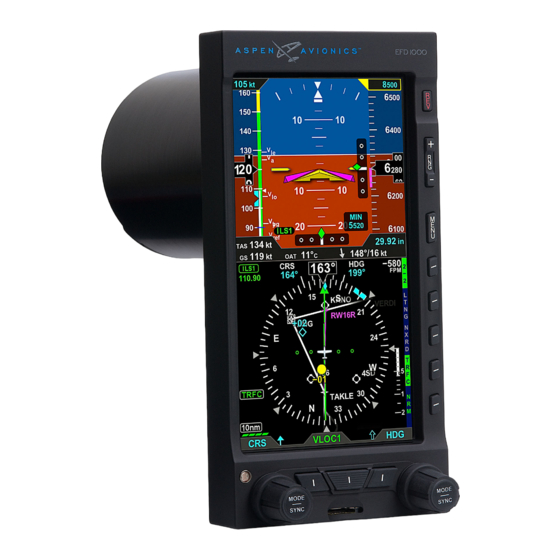
Chapter 1 Welcome and Introduction Welcome to Aspen Avionics’ Evolution Flight Display (EFD) System, the most flexible, expandable, and upgradable Electronic Flight Instrument available for general aviation aircraft. Designed to replace the attitude indicator and directional gyro. This modularity and upgradability allows the system to grow with you and your airplane, over time and affordably. - Page 21 The center of the EFD System is the E5 Dual EFI, which replaces the traditional mechanical Attitude Indicator (AI) and Directional Gyro (DG), Course Deviation Indicator or Horizontal Situation Indicator (HSI) (Figure 1-2). Figure 1-2 Single Display E5 Dual EFI NOTE Please spend some time with your aircraft flight manual supplement and avionics installer to understand exactly how your E5 is installed and configured in your particular...
-
Page 22: System Overview
1.1. System Overview Pitot Static Existing Aircraft Existing Aircraft The E5 system typically consists of four components: Pitot Line Static Line E5 Display Unit (Dual EFI) Configuration Module (CM) Remote Sensor Module (RSM) Aircraft Power EFD1000 E5 EFI Remote Analog Converter Unit (ACU) Sensor Module (Electronic Flight Instrument) - Page 23 1.1.1. E5 Dual EFI Unit Pitot & Static System Connections The E5 Dual EFI Unit is a digital system that consists of a high resolution, six-inch diagonal color LCD display, user controls, photocell, and micro SD data card slot. The three-inch diameter, four-inch deep can on the back of the display contains a non- removable electronics module that includes: 44-pin D-Sub for Electrical Connections...
-
Page 24: Configuration Module (Cm)
1.1.2. Configuration Module (CM) The Configuration Module (Figure 1-7), contains an EEPROM device that retains system configuration and calibration data and provides two primary functions: • Retains aircraft-specific configuration information, calibration data, and user settings, allowing the E5 to be swapped for service purposes without re-entering Figure 1-7 or re-calibrating the installation Configuration Module (CM) -
Page 25: Remote Sensor Module (Rsm)
1.1.4. Remote Sensor Module (RSM) The Remote Sensor Module (RSM) (Figure 1-9), is an integral part of the EFI system and works together with the display unit sensors as part of the AHRS and ADC. The RSM looks and mounts like a GPS antenna and is mounted on the exterior of the fuselage, typically aft of the cabin. -
Page 26: Controls And Display
Chapter 2 Controls and Display The E5 Dual EFI is a flat-panel LCD primary flight instrument that presents the pilot with all of the information from the traditional six-pack of mechanical instruments: Airspeed, Attitude, Altitude, Turn Coordinator, Heading Indicator and Vertical Speed Indicator (VSI). Modern technology and standard EFIS symbology enable the consolidation of all six instruments into a single display, tightening the pilot’s instrument scan and reducing pilot workload. -
Page 27: Controls & Display Orientation
2.1. Controls & Display Orientation CONTROLS ATTITUDE DISPLAY Power Button Attitude Display No Function Aircraft Reference Symbol Menu Button Roll Pointer No Function Slip/Skid Indicator Altitude Tape No Function Selected Altitude Field (controls the 360/ARC View Altitude Bug) GPSS - GPS Steering On/Off Numerical Altitude Indication, Altitude Drum/Pointer... - Page 28 DATA BAR Barometric Pressure Setting Field Ground Speed NAVIGATION DISPLAY Navigation Display Vertical Speed Tape Ownship Symbol Selected CDI Navigation Source Course Pointer Left Knob State Rate of Turn Indicator Right Knob State Ground Track Marker Hot Key Label Numerical Direction Indicator CDI TO/FROM/LOC Indicator Selected Course (CRS) Field Course Deviation Indicator...
-
Page 29: Controls
2.2. Controls The primary means for the pilot to control the EFI are the two knobs and center button at the bottom of the display. The knobs control setting CRS and HDG, and additional bugs and altitude settings. The lower center button control selection of navigation sources for the CDI. -
Page 30: Left Knob Functions
2.2.1.1. Left Knob Functions NOTE The Left Knob is used to set the Course (CRS) and Airspeed Bug (IAS). Course (CRS) is the default setting for the Left Knob. When the CDI navigation source is selected to a GPS receiver and the Auto Course is enabled in the Menu, Refer to Table 2-1 and Figure 2-2 the course is set automatically by the GPS and is not pilot-adjustable (see Section 4.4.6). -
Page 31: Sync Function
SYNC Function 2.2.1.3. Knob SYNC Function Press the Knob until its state shows the value you want to set in magenta. Press and hold the Knob for approximately one (1) second to SYNC the field’s value according to the rules shown in Table 2-2. After 10 seconds of inaction, the knob reverts to its home state (CRS or HDG), and the labels and field turn to cyan (inactive). - Page 32 Left Knob SYNC Action Course Pointer points to the VOR. CRS value is the reciprocal of the current VOR VOR navigation radial. The deviation bar centers with a “TO” indication. Course Pointer points to the active GPS waypoint. The deviation bar centers with a “TO”...
-
Page 33: Using The Knobs (Example)
2.2.1.4. Using the Knobs (Example) How to Set the Heading Bug (HDG) Rotate the Right Knob to the desired heading value, shown both by the position of the Heading Bug and the numeric value in the Selected Heading Field (Figure 2-4). The HDG label, Heading Bug and the Selected Heading Field appears in magenta After 10 seconds of inactivity, the knob defaults to HDG. - Page 34 If a navigation source is configured to be available, but is not providing valid navigation data, its navigation source annunciation will be shown with a red slash through it, and NOTE the CDI will not be shown with the Deviation Indication. The pilot is able to select the When GPS is selected as the CDI’...
-
Page 35: Hot Keys
2.2.3. Hot Keys The five keys along the lower right side of the EFI function as either single-action Hot Keys for frequently used commands or as Menu Keys when the Menu has been activated. The Hot Key functions are accessible at any time, except when the Menu is active. - Page 36 HOT KEY DESCRIPTION OPTIONS No Function No Function 360° Compass Mode Toggles between 360° and ARC 360°/ ARC modes of Navigation Display (see Section 4.4.1.) ARC Compass Mode GPSS GPSS on Toggles between GPS Steering (GPSS) Mode and HDG mode GPSS for Autopilot GPSS...
-
Page 37: Menu
2.2.4. Menu The MENU button is used to access the E5 Dual EFI’s Menu to change options, and also to change the display brightness. 2.2.4.1. Using the Menus Press the MENU button to activate the Menu (Ref. 3). The current menu page name is shown on the bottom center of the Navigation Display. - Page 38 and Table 2-4). After navigating to the Menu Page containing the option you want to change, press the Menu Key adjacent to that option label, which initiates the Menu’s Edit mode. When the Menu is in the Edit mode, the label, EDIT VALUE, is shown above the Right Knob in magenta (Figure 2-10), and the label of the item selected for editing is also shown in magenta.
- Page 39 The MENU text will display in one of the four colors listed and described in Table 2-4. Figure 2-11 DISPLAY Menu Text - Editable DESCRIPTION DISPLAY TEXT WHITE Editable option Figure 2-11 Figure 2-12 MAGENTA Editable option enabled Figure 2-12 Menu Text - Enabled for Editing GREEN Status Only...
- Page 40 Edit Main Menu Items NOTE Press the MENU Button. Navigate to the desired Menu Page. Pressing the Right Knob returns to Navigation mode Press the Menu Key of the desired option. The Menu label turns magenta, and allows selection of other menu options on different and the EDIT VALUE label displays above the Right Knob (Figure 2-16).
-
Page 41: Display Lighting
2.2.4.2. Display Lighting When the MENU button is pressed and the Menu is active, the Left Knob can be used to adjust the EFI display brightness. By default, the LCD brightness operates in AUTO mode, and is adjusted based on photocell sensing of ambient lighting conditions. -
Page 42: Range Buttons
2.2.5. Range Buttons Range Buttons have no function on the EFI. 2.2.6. REV Button The red REV Button on the EFI can be used to override automatic power control in abnormal or emergency situations (see Chapter 6, Section 6.4. and Figure 6-29 for more details). -
Page 43: Display
2.3. Display The EFI replaces the existing Attitude Indicator and DG in the center of the primary flight instrument cluster. Like the instruments it replaces, the top half presents an Attitude Display and the bottom half contains a Navigation Display (Figure 2-19). Between the two halves is the Data Bar. -
Page 44: Cleaning The Display Screen
The E5 Dual EFI generally follows standard display conventions for Electronic Flight Instrument Systems (EFIS), so a pilot with some experience and familiarity with other CAUTION EFIS displays will usually transition quickly to using the EFD1000. Pilots for whom the E5 Dual EFI is their first real exposure to EFIS and glass cockpit flying, however, should Use caution when using isopropyl alcohol as it is get some transition training from a certified flight instructor (CFI) with EFIS experience. -
Page 45: Attitude Display
2.3.2. Attitude Display The Attitude Display includes an Attitude Director Indicator (ADI), an Airspeed tape, an Altimeter tape, and approach course and glide slope indicators (Table 2-6 and Figure 2-20), (see Chapter 4, Reference Guide for more details). The Airspeed and Altitude tapes are the most obvious differences from a mechanical ADI. - Page 46 ATTITUDE DISPLAY Attitude Display Aircraft Reference Symbol Roll Pointer Slip/Skid Indicator Altitude Tape Selected Altitude Field Numerical Altitude Value, Altitude Drum/Pointer Altitude Bug Airspeed Tape Selected Airspeed Field Airspeed Bug Numerical Airspeed Value, Airspeed Drum/Pointer Table 2-6 Attitude Display Components Figure 2-20 Attitude Display Components 091-00086-001 ( )
-
Page 47: Attitude Director Indicator (Adi)
2.3.2.1. Attitude Indicator (AI) The Attitude Indicator (AI) features a conventional blue (sky) over brown (ground) background, with a white horizon line dividing the two areas. A triangular Aircraft Reference Symbol (Ref. 17) is in a fixed position and shows aircraft attitude relative to Figure 2-21 the horizon. -
Page 48: Airspeed Tape And Bug
2.3.2.2. Airspeed Tape and Bug Airspeed is indicated by a moving airspeed tape against a fixed position airspeed pointer, shown on the left-hand side of the Attitude Display (Figure 2-22). A numerical, rolling drum readout indicating airspeed values to the closest one knot or mile per hour is provided adjacent to the fixed pointer. - Page 49 The pilot can set a target airspeed using the Left Knob (see Section 4.2.2.1.). The target airspeed is shown on the Airspeed Tape as an Airspeed Bug with its setting displayed numerically above the Airspeed Tape. The Airspeed Bug and numerical value are for visual reference only, to help the pilot maintain a target airspeed;...
-
Page 50: Data Bar
2.3.3. Data Bar The Data Bar visually separates the upper and lower halves of the display. GPS Ground Figure 2-24 Speed (GS) and Barometric Pressure Setting are presented in the Data Bar (Table 2-7 Data Bar Components and Figure 2-24). When any of these values are not available or invalid, the corresponding data field is dashed. -
Page 51: Navigation Display
2.3.4. Navigation Display The lower half of the EFI is the Navigation Display (Table 2-8 and Figure 2-35), which shows a wide range of navigation information and flight data, including: • Course Pointer and Heading Bug. • 360° and ARC Compass rose display modes. •... -
Page 52: Numerical Direction Indicator
NAVIGATION DISPLAY Navigation Display Vertical Speed Numerical Value Ownship Symbol Vertical Speed Indicator Tape Course Pointer Select CDI Navigation Source Rate of Turn Indicator Left Knob State Ground Track Marker Right Knob State Numerical Direction Indicator Hot Ket Legend Selected Course (CRS) Field CDI TO/FROM/LOC Indicator Selected Heading (HDG) Field CDI Lateral deviation indicator... - Page 53 2.3.4.1. Numerical Direction Indicator The center of the Navigation Display is the Numerical Direction Indicator. Like a magnetic compass, the NDI always shows the current magnetic heading of the aircraft. This NDI compensates both for the turning and acceleration errors exhibited by wet compasses and for precession errors found in common Directional Gyros.
- Page 54 Navigation Information Regardless of Compass Mode setting, the current magnetic heading is always shown at the top center of the Navigation Display (Figure 2-2, Ref. 35 and Figure 2-28). The HDG Bug setting is shown in the Selected Heading Field (Figure 2-2, Ref. 37). This field is always visible even if the HDG Bug itself is only partially visible in ARC Compass Mode.
-
Page 55: Course Pointer And Course Deviation Indicator (Cdi)
2.3.4.2. Course Pointer and Course Deviation Indicator (CDI) In the 360º Compass Mode, the Course Pointer and CDI displays an arrowhead pointing to the selected course, and a fixed CDI at the bottom of the display, similar to the LDI and resembling that used in contemporary GPS navigation displays. -
Page 56: Rate Of Turn Indicator
Auto Course Select is indicated by an inverse A on a green background, adjacent to both the numerical CRS value and the CRS Left Knob State. (Figure 2-33 and Figure 2-34). Figure 2-33 If the GPS navigator enters the OBS or HOLD mode, Auto Course Select is automatically Auto Course Indication on CRS Field disabled until the GPS navigator resumes waypoint sequencing. -
Page 57: Vertical Speed Indicator (Vsi)
2.3.4.6. Vertical Speed Indicator (VSI) Whenever the vertical speed exceeds +/- 100 feet per minute (fpm), the vertical speed is indicated by a rising/sinking white vertical tape and associated scale markers immediately to the right of the compass rose (Figure 2-2, No. 40 and Figure 2-36). A numerical value of the aircraft’s vertical speed is shown directly above the tape, in the upper right-hand corner of the Navigation Display (Figure 2-2, No. -
Page 58: Chapter 3 Flying The Dual Efi
Chapter 3 Flying the E5 Dual EFI This chapter provides an overview of flying the EFI on a cross-country flight, explaining how to access and change the necessary settings of the EFI. While you can jump right in to using the EFI with this chapter, it may be helpful to first read Chapter 2 to become more familiar with the controls, operating logic, and display elements. - Page 59 FEATURE SETTING FEATURE SETTING Barometric Selected Pressure Allows for BARO Set as desired Altitude (BARO) Hot adjustment Map RNG No E5 Dual EFI Left and Right No E5 Dual EFI (Range) Functionality Buttons functionality Buttons Barometric Navigation Pressure Adjustable Source Select Select as desired Setting Field (Middle...
-
Page 60: Quick Controls Overview
3.1. Quick Controls Overview Chapter 2 explains the EFI controls in detail. The following is a quick summary: Knobs (See Chapter 2, Section 2.2.1. for details) The Left or Right Knob each has a Home State, to which it returns after 10 seconds of inactivity. - Page 61 Navigation Source Buttons • Buttons at the bottom of the display couple the available navigation sources to the CDI. • The Center Button - CDI Navigation Source Select Button (Figure 3-1, Ref. 9) selects the nav source to couple to the CDI and to drive the autopilot (if installed).
-
Page 62: Example Flight Scenario
3.2. Example Flight Scenario This section will walk you through using the EFI on a flight from Albuquerque International Sunport (KABQ) to Reno/Tahoe International Airport (KRNO), flying NOTE Victor airways. This scenario uses one pilot’s technique for setting up the navigation The tasks and procedures you will use in your airplane instruments, but there are many other valid possibilities. -
Page 63: Pre-Departure (Startup)
3.2.1. Pre-Departure (Startup) Once the pre-flight inspections and checklists are complete, start the engines and turn on the EFI Master switch. When power is applied the bezel backlighting illuminates and within a few seconds the splash screen displays while it initializes and the AHRS data is validated (Figure 3-2). As the software initializes and the EFI warms up, the Attitude and Navigation Displays will appear first (typically around 30 seconds), with red X’s showing for the airspeed and altitude tapes and the CDI Navigation Source is slashed as invalid (Figure 3-3). - Page 64 Turn the Avionics Master ON. Until the navigation radios are operational, the CDI Navigation Source annunciations on the EFI is slashed as invalid (Figure 3-4), and the GPS1 caution annunciation on the left (Figure 3-5), display. The CDI Navigation Source Select will default to VLOC1 the first time the EFI is turned on.
- Page 65 Once the radios are available, we listen to the ATIS and learn that the local altimeter setting is 30.15 and that Runway 8 is in use for departures. WARNING First set the standby altimeter to 30.15, and then set the EFI barometric pressure setting. Whenever there is a new altimeter setting, set both the E5 Dual EFI and the standby altimeter.
- Page 66 Next, since we’ll be departing from Runway 8, we set our Heading Bug to runway heading, 080°. Set the Heading Bug Press the Right Knob until HDG displays above the knob and the HDG field is enabled for editing, both rendered in magenta (Figure 3-8). The Heading Bug will also be rendered in magenta, and a dashed magenta line will extend from the ownship symbol to the Heading Bug to make it easier to see the bug position.
- Page 67 Select GPS1 as the CDI Navigation Source. Because we have enabled Auto Course Select, the Course Pointer automatically slews to 261º (the initial course from the airport to the first fix on the LARGO2 departure, ABQ VOR). Select the CDI Navigation Source •...
- Page 68 Altitude Next, we set our assigned initial altitude of 7,000 feet in the Selected Altitude Field. We press the Right Knob twice, changing the legend above the knob to ALT in magenta. Then we turn the Right Knob to set 7,000. This will help us capture and maintain our assigned altitude.
- Page 69 Our normal climb speed is 120 KIAS, so we set the Airspeed Bug as a reminder. To do so, we press the Left Knob twice, until it shows IAS in magenta above the knob. Then turn the knob until 120 shows in the Selected Airspeed Field. Set the Airspeed Bug Press the Left Knob until IAS displays above the Left Knob and the Selected Airspeed field and bug are enabled for editing, all three rendered in magenta...
-
Page 70: Departure
3.2.2. Departure As we start the takeoff roll, we note the airspeed on the airspeed comes “alive” at 20 KIAS. All indications are normal, so we continue the takeoff, rotate at 80 KIAS. As we run out of usable runway to land, we bring the gear up, and soon we’re over the end of the Figure 3-17 13,800 ft. - Page 71 Auto Course Select has already set our Course Pointer to the 255º course from ABQ to ZUN and a 220º heading sets us up for a nice intercept. We pitch a little higher to climb at 115 KIAS through 8,000 for traffic, then lower the nose to maintain our target airspeed of 120 KIAS by reference to the Airspeed Bug.
-
Page 72: Enroute
3.2.3. Enroute Albuquerque Center gives us a new altimeter setting of 30.11. We set 30.11 on the standby altimeter and then on the EFI. • Press the BARO Hot Key and rotate the Right Knob to set 30.11. • Press the BARO Hot Key, or any knob, button/key to exit. Soon, the CDI comes “alive”... - Page 73 With GPS Steering (GPSS), a compatible GPS navigator (in this case, a Garmin 430W) drives the autopilot directly via the autopilot’s HDG mode, telling it how to bank to stay centered on course. GPSS can drive the autopilot far more accurately than the NAV mode (which is based on course deviation indications) because the GPS always knows the ground track and how to adjust to maintain that track, implicitly accounting for changing wind conditions.
-
Page 74: Conclusion
3.3 Conclusion The E5 Dual EFI is a powerful addition to any cockpit, providing far more capability, CAUTION information and automation than the mechanical instruments it typically replaces. While it is simple and intuitive enough to start using with only a short orientation, fully The Garmin 400/500 series navigators continue to understanding and exploiting all of its features require some study and experience. -
Page 75: Chapter 4 Reference Guide
Chapter 4 Reference Guide The E5 Dual EFI is a panel-mounted Electronic Flight Instrument System (EFIS) that presents the pilot with displays of attitude, altitude, indicated airspeed, heading, rate of turn, slip/skid, and navigation course deviation information. The system also displays supplemental flight data, such as groundspeed and pilot-selectable indices (bugs), to increase situational awareness and enhance flight safety. -
Page 76: Air Data, Attitude And Heading Reference System (Adahrs)
4.1. Air Data, Attitude and Heading Reference System (ADAHRS) One of the many benefits of glass cockpit systems like the Aspen Evolution system is that they replace old, less-reliable mechanical instruments and sensors with electronic equivalents. For aircraft primary flight instruments, spinning metal gyros are replaced with electronic gyros and accelerometers, and mechanical air data instruments (airspeed indicator, altimeter, and VSI) are replaced by electronic sensors to measure static and ram air pressures. -
Page 77: Attitude
4.1.1. Attitude The Aspen ADAHRS attitude solution uses inputs from its internal three-axis accelerometers, rate gyros, and magnetometers, supplemented by ram and static air pressure inputs from the aircraft pitot-static system. Failures or incorrect input from any of these sensors (such as might occur if the pitot tube or static system become blocked) will affect the attitude solution. -
Page 78: Pitot Obstruction Monitor
4.1.2. Pitot Obstruction Monitor Most light aircraft have only a single pitot and static system available for flight instrument use. As such, a common pitot and static input is shared between the EFI and analog standby instruments. Should one or both of these pitot and static lines become blocked, both the EFI and any standby airspeed and altitude indicators could display erroneous airspeed and altitude information. -
Page 79: Heading
In summary, loss or degradation of the EFI attitude solution is unlikely if the pilot assures the proper operation of the pitot-static system. If the pitot or static system becomes blocked, an ADAHRS internal sensor fails, or a CROSS CHECK ATTITUDE followed by an ATTITUDE DEGRADED indication is frequent or persists, the attitude indication on the EFI should be considered to be compromised. -
Page 80: Free Gyro Mode
Just like other compass systems, the accuracy of the fluxgate is affected by its location on the airframe. Ferrous metal structures, electrical fields produced by motors, pumps, wiring, magnets in cabin speakers and other airframe-related sources of interference either constant or momentary (i.e. operating an electric trim motor, windshield heat, pumps, etc) can all affect the accuracy of the compass. -
Page 81: Degraded Adahrs Performance
Two minutes after detection, a FREE GYRO MODE annunciation will be presented across the Navigation display, indicating the heading system no longer can be aligned with magnetic north. Some precession of the heading is possible, especially during abrupt maneuvers. If the condition persists for four more minutes (six minutes total) the attitude and heading indicators will be removed and replaced with red X indications. -
Page 82: Attitude Display
4.2. Attitude Display 4.2.1. Attitude Indicator The Attitude Indicator consists of an aircraft reference symbol on a blue (sky) and brown (ground) background. The white horizon line separates the sky from the ground and extends to the edge of the display. The Roll Scale curves over the top of the Attitude Indicator while the Pitch Scale extends vertically in the middle. -
Page 83: Roll Scale
4.2.1.1. Roll Scale The Roll Scale is displayed at the top of the Attitude Indicator and comprises a moving scale set against a fixed, white, triangle roll pointer (Figure 4-3, Ref 6 & 7). Tick marks are displayed at 0º, 10º, 20º, 30º, 45º, and 60º of roll. The 45º marks are triangles. 4.2.1.2. -
Page 84: Airspeed Indicator
4.2.2. Airspeed Indicator The Airspeed Indicator comprises a moving tape, airspeed bug, and numerical airspeed value (drum). Textual Vspeeds, color Speed Bands, and Speed Markers are also rendered on the moving tape (Figure 4-7). Selected Airspeed Field Color Speed Bands Textual Vspeeds Initial Flap Extension Speed Marker Airspeed Tape... - Page 85 Indicated airspeed is displayed in knots, miles per hour or Mach number, set at installation, with tick marks rendered on the Airspeed tape every ten (10) units. Speed Bands and Speed Markers are configured during installation and cannot be changed or removed by the pilot.
-
Page 86: Selected Airspeed
4.2.2.1. Selected Airspeed The Selected Airspeed Field value and associated Airspeed Bug are shown on the Airspeed Tape. The Selected Airspeed Field value is shown at the top of the Airspeed Tape. The Airspeed Bug is displayed next to the Airspeed Tape when the Selected Airspeed value is within the visible range of the tape. -
Page 87: Airspeed Display
4.2.2.2. Airspeed Display The airspeed tape can be turned off at the pilot’s discretion to facilitate screen declutter. This setting will be retained when the system is turned off then powered on again. Hide/Display Airspeed Tape Press MENU Button. Rotate Right Knob until first Menu Key displays TPS (Figure 4-12). Press TPS Menu Key. -
Page 88: Altimeter
4.2.3. Altimeter The altimeter comprises an Altitude Bug, Numerical Altitude Value (drum), Altitude Tape, and Selected Altitude Field value. (Figure 4-14). Selected Altitude Field Numerical Altitude Value Altitude Tape The Altitude Tape range is from -1,600 to 51,000 feet. Major tick marks are provided every 100 feet and minor tick marks every 20 feet. -
Page 89: Barometric Units Of Measure
If the altitude exceeds 51,000 feet, the Numerical Altitude Value is dashed, and the tape is frozen at this limit. All altitude information is removed and replaced with a red X with the textual annunciation of ALT FAIL when altitude data is invalid (Figure 4-15). Figure 4-16 Baro Shown in Inches of Mercury 4.2.3.1. - Page 90 Set the Barometric Pressure Press the BARO Hot Key. The BARO label above the Right Knob and Barometric Pressure Setting Field appear in magenta (Figure 4-21). Rotate the Right Knob to change the value of the Barometric Pressure Setting Field. Press the BARO Hot Key or any knob, button/key to exit.
-
Page 91: Selected Altitude Field
4.2.3.2. Selected Altitude Field NOTE The Selected Altitude Field value is displayed at the top of the Altitude Tape. The Selected Altitude Field range is 100 to 51,000 feet, in 100 foot increments. The default Rotating the knob quickly will change the altitude value for the Selected Altitude value is 100 feet, or the previously set value. -
Page 92: Altitude Display
4.2.3.3. Altitude Display NOTE The altitude tape can be turned off, at the pilot’s discretion, to facilitate screen declutter. Both Airspeed and Altitude tapes are affected by this action. A E5 Dual EFI installation sets the tapes display to UNLOCKED, allowing the pilot to display or hide the Hide/Display Airspeed and Altitude Tape Airspeed and Altitude tapes as desired. -
Page 93: Data Bar
4.3. Data Bar The Data Bar presents GPS, Ground Speed (GS), and Barometric Pressure Setting, as shown in Figure 4-25. The Data Bar is always present on the display. Invalid or out-of-range Data Bar values are dashed. Ground Speed (GS) Barometric Pressure Setting Figure 4-25 4.3.1. -
Page 94: Navigation Display
4.4. Navigation Display The Navigation Display of the E5 Dual EFI, combines a Direction Indicator with a Course Deviation Indicator (CDI) (Figure 4-26). The Direction Indicator comprises a compass, numerical direction indication, heading bug, Ground Track Marker (when GPS ground track information is available), rate of turn indicator, and aircraft ownship symbol. -
Page 95: Compass
All Magnetic Headings are displayed in degrees. The value range is from 001° - 360°, always displayed in three digits, and use leading zeros when applicable. The Magnetic North is expressed as 360°. 4.4.1. Compass The EFI offers two Compass Modes: 360°, CDI, and ARC CDI. The aircraft’s heading is always expressed degrees magnetic. - Page 96 Select Compass Type Press the 360/ARC Hot Key (Figure 4-29) to alternately select either the 360° or ARC Compass Mode. The Navigation Display changes and the Hot Key label reflects the currently selected Compass Mode (Figures 4-30 and 4-31). Figure 4-30 ARC Compass Mode Figure 4-29 360/ARC Hot Key...
-
Page 97: Course Pointer
4.4.2. Course Pointer For all Compass Modes, the arrowhead of the Course Pointer aligns with the corresponding value on the compass scale regardless of the aircraft heading. The ARC CDI Course Pointer is described in Table 4-2. COMPASS DESCRIPTION The Course Pointer is shown as a stub arrow or tail whenever the CRS value ARC CDI or its reciprocal falls within the displayable range of the compass scale arc (Figure 4-32 and 4-33). -
Page 98: To/From Indicator
4.4.3. TO/FROM Indicator Each of the Compass Modes has a TO/FROM indicator. The TO/FROM indicator shows whether the aircraft is heading toward a waypoint or radio navaid, or from a waypoint or radio navaid. For each Compass Mode, the TO/FROM indication is slightly different, as described in Table 4-3. -
Page 99: Course Deviation Indicator And Scale
4.4.4. Course Deviation Indicator and Scale Selected course deviation is depicted by a Course Deviation Indicator and Scale. Deviation is indicated by positioning the Course Deviation Indicator on the Scale corresponding to the lateral deviation value. Course Deviation Indicator Course Deviation Scale Figure 4-37 The ARC CDI Compass Mode’s CDI and Scale are located at the bottom of the lower Course Deviation Indicator, DI Compass Mode... - Page 100 Refer to the GPS or VHF NAV AFMS for information on the operation of the connected navigation equipment. NOTE There are many radio configurations available. Your authorized Aspen Avionics Dealer can explain the configuration used on your aircraft. Figure 4-39 CDI Source selection and Information...
-
Page 101: Auto Course
4.4.6. Auto Course The pilot can either use the Auto Course (AUTOCRS) or manually set a CRS value. When the selected CDI Navigation Source is a connected GPS receiver and AUTOCRS is enabled, CRS is not adjustable (current course value is automatically slewed and controlled by the desired track from the GPS). -
Page 102: Cdi Selected Course
Disable Auto Course Press the MENU Button. Rotate the Right Knob to the GENERAL SETTINGS page (Figure 4-43). Press the AUTOCRS Menu Key. The Menu label turns magenta, and the EDIT VALUE label displays above the Right Knob (Figure 4-44). Rotate the Right Knob to select DISABLE (Figure 4-45). -
Page 103: Heading Bug
4.4.8. Heading Bug The EFI offers a pilot-selectable Heading Bug. The Heading Bug symbol is positioned on the compass scale according to the Selected Heading Field value (HDG) set by the pilot (Figure 4-47). When the Selected HDG Field value is outside the visible compass scale range in the ARC Compass mode, only a portion of the Heading Bug is shown at the edge of the Figure 4-47 Heading Bug and Selected... -
Page 104: Aircraft Heading Display
4.4.9. Aircraft Heading Display The aircraft heading is displayed in degrees magnetic (Figure 4-50). If the aircraft’s heading is unavailable or invalid, all heading and navigation information, Figure 4-50 including the CDI is removed and replaced with a single red X covering the entire lower Direction of Flight Numerical Display display area, along with the annunciation DIRECTION INDICATOR FAIL (Figure 4-51). -
Page 105: Ground Track Marker
4.4.11. Ground Track Marker When configured with a GPS that provides ground track data, a Ground Track Marker is displayed on the compass scale to indicate the aircraft’ s ground track. This marker may be used to compensate for wind drift during flight (Figures 4-54 and 4-55). The Ground Track Marker is removed from the display when ground track data is not available or invalid. -
Page 106: Vertical Speed Indicator
4.5. Vertical Speed Indicator When the 360° Compass Mode is selected, the Vertical Speed Indicator (VSI) is rendered on the right side of the Navigation Display, showing a numerical and graphical representations of vertical speed. The VSI shows the change in pressure altitude over time. -
Page 107: Autopilot Integration
4.6. Autopilot Integration NOTE The EFI can connect with many different legacy autopilot systems that are typically Refer to the autopilot AFMS for information on the found in general aviation aircraft. Autopilot integration is limited to heading and operation of the autopilot. navigation modes. -
Page 108: Gps Steering (Gpss)
4.6.1. GPS Steering (GPSS) WARNING GPS Steering represents a modern approach to flying between flight plan waypoints, and offers many advantages of over traditional methods of flying direct course lines GPS Steering is a powerful automation tool that between waypoints. can substantially reduce pilot workload. - Page 109 The EFI translates GPS Steering commands received over a digital data bus into a signal that is compatible with the autopilot Heading channel. Thus, by selecting GPSS Hot Key NOTE on the EFI and the Heading mode of the autopilot, the autopilot is able to fly Refer to the Aircraft Flight Manual Supplement for your GPSS commands.
- Page 110 When GPSS is enabled, and the autopilot is in HDG mode, the autopilot will follow the steering commands from the GPS. A GPSS enabled state will be indicated on the EFI in two locations: 1) the GPSS legend adjacent to the GPSS Hot Key will be shown in inverse green;...
- Page 111 With GPSS enabled on the EFI and the autopilot in HDG mode, the GPSS will steer the autopilot laterally through the flight plan using GPS, even after the GNS-430 CDI WARNING automatically switches to VLOC, and the EFI navigation source similarly switches to VLOC.
-
Page 112: Typical Autopilot Operations
4.6.2. Typical Autopilot Operations NOTE Whenever the EFI’s installed configuration includes connections to GPS, VLOC, and autopilot systems, it acts as a data conduit between the navigators and the autopilot. Refer to the autopilot systems Aircraft Flight Manual This enables any compatible navigator to be coupled to the autopilot. Supplement and/or POH for details regarding use and operation of the autopilot system. - Page 113 HDG Mode Operation – Heading Bug Steering NOTE Set the Heading Bug to the desired heading (Section 4.4.8). Verify that GPSS is not selected. When GPSS is enabled, the Heading Bug is not coupled Select the autopilot’s Heading (HDG) mode. to the autopilot.
- Page 114 NAV Mode Operation – GPS Navigation NOTE With a valid flight plan programmed and active in the GPS, use the CDI Source Select button to couple the GPS to the EFI (see Section 4.4.5.). Not all autopilots operate in the manner described If AUTOCRS is disabled, set the Course Pointer to the desired course (CRS) here for intercepting courses.
-
Page 115: Menu Overview
Chapter 5 Customizing the E5 Dual EFI 5.1. Menu Overview The following tables and figures provide a brief overview of each menu page and its menu options. KEY DESCRIPTION OPTIONS Displays Airspeed and DISABLE or ENABLE Altitude Tapes BARO (in/mB): BARO (in/mB): Figure 5-1 GENERAL SETTINGS A... - Page 116 KEY DESCRIPTION OPTIONS KEY DESCRIPTION OPTIONS 0 to 450 or LOCKED VSPEEDS DISABLE or ENABLE 0 to 450 or LOCKED 0 to 450 or LOCKED 0 to 450 or LOCKED 0 to 450 or LOCKED 0 to 450 or LOCKED Vref 0 to 450 or LOCKED Table 5-3...
- Page 117 KEY DESCRIPTION OPTIONS Operating from or Switch to Battery Power. Green when current state (Pressing key performs no action). White if selection is Status or Action possible. Operating from or Switch to External Power. Green when current state (Pressing key performs no action). White if selection is Status or Action possible.
- Page 118 KEY DESCRIPTION OPTIONS Main Application Processor Software Version Status Only Input Output Processor Software Version Status Only Unit Serial Number Status Only Table 5-5 Menu – SYSTEM STATUS Figure 5-5 SYSTEM STATUS 091-00086-001 ( ) Page 5-4 EFD1000 E5 Pilot’s Guide...
-
Page 119: Configuring Vspeeds
5.2. Configuring Vspeeds Vspeeds (Figure 5-6) are used to designate different operating speeds of the aircraft and are defined in Table 5-6 . High Speed Red MOL or Vspeed DEFINITION PRE-SET ADJUSTABLE PRE-SET Vne (power-on) BANDS TEXT LABELS MARKERS Never exceed (Red Line) Vno (Structural Cruise) Maximum structural... - Page 120 Vspeed DEFINITION PRE-SET ADJUSTABLE PRE-SET NOTE BANDS TEXT LABELS MARKERS Setting the value of the white triangle, Vyse, and Vmc Maximum landing gear operating markers to zero (0) during installation disables the speed markers. Setting any of the adjustable Vspeed values to (Multi-engine) Single-engine zero (0) disables the associated label.
- Page 121 BAND COLOR SPEED RANGE NOTE Red or Barber Pole Band Vne/MOL Never Exceed/Maximum Operating Limit On aircraft without flaps, the white band is disabled, (High Speed) and the green band is shown full width, as there isn’t Yellow or Clear Vno - Vne Caution Range an applicable Flap Extend (Vfe) or Full Flap Stall (Vs0)
- Page 122 On aircraft with flaps, setting the upper and lower thresholds of the white and/or yellow bands to the same value disables the applicable band. When disabled, the band does not display. When using the Vspeed textual markers, the pilot must first ENABLE the display of the markers and then set values for each Vspeed.
- Page 123 Set Textual Vspeed Labels Press the MENU Button. Rotate the Right Knob to the appropriate Vspeed Menu page (Figure 5-11). Press the appropriate Vspeed Menu Key. The Menu label turns magenta, and the EDIT VALUE label displays above the Right Knob (Figure 5-12). Rotate the Right Knob to the desired value (Figure 5-13).
-
Page 124: Lcd Brightness Control
5.3. LCD Brightness Control The LCD brightness of the EFI operates in either of two modes, Automatic or Manual. The LCD brightness range is displayed as a value from 1–100, displayed above the Left Knob. LCD MODE DESCRIPTION AUTOMATIC LCD backlight intensity is automatically adjusted based on the ambient BRT AUTO lighting conditions sensed by the Automatic Dimming Photocell (Figure Figure 5-14... -
Page 125: Expanded Emergency And Abnormal Procedures
Chapter 6 Expanded Emergency and Abnormal Procedures This section supplements and provides an expanded description of the emergency and abnormal procedures included in the FAA-approved Aircraft Flight Manual Supplement. The information provided here is intended to provide additional background information to enhance the pilot’s understanding of the emergency and abnormal conditions and the associated procedures provided in the AFMS. -
Page 126: Pitot/Static System Blockage
6.1. Pitot/Static System Blockage A pitot line blockage will result in the airspeed indicator behaving like an altimeter when the aircraft’s altitude changes, and it will not respond to airspeed changes. A pitot line blockage can also affect the EFI’s attitude indication. A static line blockage will result in altitude remaining fixed and a zero vertical speed despite aircraft pitch and/or power setting changes. -
Page 127: Identifying And Handling Suspected Pitot And/Or Static System Failures
Blocked Pitot or Static Line Suspected Turn Pitot heat ON Open the Alternate Static Source Refer to alternate, airspeed, altitude, and heading sources for primary flight information Consider exiting IMC Land as soon as practicable 6.1.1. Identifying and Handling Suspected Pitot and/or Static System Failures Blocked pitot and/or static system ports will degrade the EFI’s attitude solution. - Page 128 On the initial climb-out after takeoff, it is also good practice to note and call out passing through a pre-determined altitude above ground level (AGL) a couple of minutes after takeoff and ideally before entering the clouds (e.g., “2,000 feet”). If your primary and backup instruments are not showing the altitude and airspeed you normally expect to see at that point, you might have partially blocked static system ports.
- Page 129 Airspeed going to zero is by far the most common symptom of a blocked pitot tube. If you see either of these indications of a blocked pitot tube, the first thing to do is turn on the pitot heat to remove any ice blockage. This will quickly restore the normal attitude and airspeed indications on the EFI systems (it takes about 40 seconds to recover after the pitot pressure is restored).
-
Page 130: Frequent Or Persistent Cross Check Attitude Annunciation
6.2. Frequent or Persistent CROSS CHECK ATTITUDE Annunciation Refer to alternate airspeed, altitude, and heading sources for primary flight information. Consider the following: CROSS CHECK ATTITUDE Turn Pitot heat ON. Consider exiting IMC. Land as soon as practicable For a detailed explanation of when and why the EFI may display a CROSS CHECK ATTITUDE annunciation, either momentarily or persistently, see Chapter 4, Section 4.1. -
Page 131: Abnormal Shutdown Procedure
6.4. Abnormal Shutdown Procedure The E5 Dual EFI is typically powered through a master switch that is connected to the aircraft’s bus. Normally, the EFI will power down when the EFI Master switch is turned OFF or when aircraft power is removed when on the ground. To force the display to power down, the following procedures are provided. -
Page 132: Loss Of Aircraft Electrical Power
6.5. Loss of Aircraft Electrical Power In the event that aircraft generated power is degraded or fails, the E5 Dual EFI will automatically switch to its own dedicated battery (Figure 6-3). When continued safe operation depends on the EFI, UNRESTORABLE LOSS OF EXTERNAL POWER IS AN EMERGENCY SITUATION. -
Page 133: Overvoltage Protection
6.5.1. Overvoltage Protection In the event of an overvoltage condition in the aircraft’s electrical system, (greater than 33 volts) the EFI will automatically switch to its battery power and continue to operate without any pilot action. Operation from the aircraft electrical system will not be possible while the overvoltage condition is present. - Page 134 NOTE WARNING When operating on the internal battery, the display When fully charged, the internal battery will power the E5 Dual EFI to provide ADAHRS backlight intensity is limited to a value of 70. for a minimum of 30 minutes in temperature extremes and much longer in normal operating temperatures (Refer to the AFMS).
-
Page 135: Power Override
6.6. Power Override NOTE In the event that the pilot wishes to override the EFI’s automatic power configuration, When airborne, if the EFI’ s input voltage is below the proceed as follows: 12.8V (14V Electrical System) or 25.6V (28V Electrical System) automatic battery transition threshold, and Power Override EXT PWR is selected through the POWER SETTINGS... -
Page 136: In-Flight Ahrs Reset
6.7. In-Flight AHRS Reset If the attitude pitch or roll data become invalid, a red X and the textual annunciation of ATTITUDE FAIL replaces the Attitude Indicator, and all aircraft roll, pitch, and slip information is removed from the Attitude Display (Figure 6-6). Use alternate, mechanical flight instruments for primary flight information and reset the AHRS as soon as possible. - Page 137 Perform an In-Flight AHRS Reset Maintain straight and level flight. Consider exiting IMC. Fly by visual reference or by other instruments. Disconnect the autopilot. Press the MENU Button. Rotate the Right Knob to display the GENERAL SETTINGS A Menu page. Press the AHRS RESET? Menu Key (Figure 6-7).
-
Page 138: Gpss Operation, Annunciations, And Autopilot Modes
6.8. GPSS Operation, Annunciations, and Autopilot Modes The E5 Dual EFI offers GPSS. Four modes, Enable, Disable, Unavailable and Coast (Wings Level), are possible and annunciated in the Navigation Display. When enabled, the configured GPS source passes GPSS as the heading input to a configured autopilot. When engaged, a configured autopilot will interpret GPSS commands as heading inputs and follow the active GPS flight plan, including anticipated turns, if provided. - Page 139 The Wings Level mode removes roll steering inputs to the autopilot, causing the aircraft to roll wings level, and displays a red slash through the annunciated A HDG and GPSS# source. The amber GPSS Hot Key label requires pilot action. If this occurs, do the following: When GPSS Automatically Changes to Wings Level Mode Check the configured GPS source.
-
Page 140: Warning, Caution, And Advisory Summary
6.9. Warning, Caution, and Advisory Summary WARNINGS Presented when the EFI is operating on the internal battery. The countdown timer begins at 15 seconds and is then replaced by the ON BAT annunciation with the battery’s % charge remaining. NOTE If the battery temperature is less than 0°... - Page 141 WARNINGS When the Attitude Indicator display extreme pitch up or extreme pitch down attitudes, the red chevrons indicate the direction to restore level flight. Figure 6-16 Figure 6-17 Chevrons indicate Pitch Down Chevrons indicate Pitch Up Table 6-1 Warning Annunciations 091-00086-001 ( ) Page 6-17 EFD1000 E5 Pilot’s Guide...
- Page 142 CAUTION Presented when the EFI AHRS internal integrity monitor determines that attitude is potentially degraded. When a CROSS CHECK ATTITUDE annunciation is presented, the pilot should cross check attitude, airspeed, and altitude indications with other sources of primary flight information. Figure 6-18 Cross Check Attitude The CHECK PITOT HEAT annunciation accompanies the ATTITUDE FAIL annunciation and is...
- Page 143 CAUTION Presented when a configured GPS source’s data is invalid or unavailable. Figure 6-20 GPS Invalid Presented to indicate that the EFI is using GPS Ground Speed vice IAS as part of the AHRS solution. Recommended action is to check for PITOT/STATIC blockage. Figure 6-21 Attitude Degraded Presented when the previously enabled and valid GPSS source is lost or has changed.
- Page 144 ADVISORY Presented when the REV Button is pressed. Figure 6-23 REV Button Off Presented when GPSS is enabled and the GPS source is valid. This also indicates the autopilot heading source Figure 6-24 GPSS On 1. May require ACU option 091-00086-001 ( ) Page 6-20 EFD1000 E5 Pilot’s Guide...
- Page 145 ADVISORY A horizontal red line through the Selected CDI Navigation Source indicates that the data from the source is invalid or unavailable. Figure 6-25 Navigation Source Invalid or Unavailable GPSS Hot Key label with a blue background and gray letters indicate that the GPSS is unavailable. Figure 6-26 GPSS Unavailable Table 6-3 Advisory Annunciations...
-
Page 146: Chapter 7 Appendices
Chapter 7 Appendices 7.1. Operating Limitations Refer to the latest version of the Airplane Flight Manual Supplement (AFMS), Aspen Avionics document 900-00008-001 for the limitations that apply to your specific aircraft installation. The AFMS and this Pilot’s Guide must be carried in the aircraft and be immediately available to the pilot while in flight. - Page 147 View the Main Application Processor Software Version Press the MENU Button. Rotate the Right Knob to the SYSTEM STATUS Menu page. The MAP VER Menu Key displays the current Main Application Processor Software Version (Figure 7-1). Press the MENU Button to exit. Figure 7-1 View Main Application Processor Software Version...
-
Page 148: Specifications
7.3. Specifications 7.3.1. E5 Dual Electronic Flight Instrument (EFI) GENERAL SPECIFICATIONS Width 3.50 in. (Measured at Bezel) Height 7.00 in. (Measured at Bezel) Can Depth 4.15 in. (Rear of Bezel to Rear of Can) Overall Depth 6.35 in. (Knob to Rear Pressure Fitting) Weight 2.9 lbs. - Page 149 Input Voltage +8 to +32 Volts DC Max Current 2.4 Amps @ 28 VDC 4.8 Amps @ 14 VDC I/O SPECIFICATIONS ARINC 429 Inputs ARINC 429 Outputs RS-232 Inputs RS-232 Outputs Pitot / Static Quick Connect CERTIFICATION SPECIFICATIONS Software ASTM F3153-15 Environmental RTCA DO-160E Categories...
-
Page 150: Remote Sensor Module (Rsm)
7.3.2. Remote Sensor Module (RSM) Width 2.65 in. Length 4.40 in. Height 1.00 in. Weight 0.2 lbs. Input Voltage Provided by EFI Max Current Included in EFI Current Table 7-2 Remote Sensor Module (RSM) Specifications 7.3.3. Analog Converter Unit (ACU) Width 5.75 in. -
Page 151: Operational Specifications
7.3.4. Operational Specifications Airspeed Range Minimum displayed airspeed 20 KIAS Maximum displayed airspeed 500 KIAS Altitude Range Minimum displayed altitude -1,600 ft. MSL Maximum displayed altitude 51,000 ft. MSL Vertical Speed Maximum displayed vertical speed rates (tape) +/-2,000 fpm Range Maximum displayed vertical speed rates (numerical +/- 9,990 fpm value) -
Page 152: Glossary
7.4. Glossary AWOS Automated Weather Observation System ºC Degrees Celsius Back Course Localizer back course approach where the ºF Degrees Fahrenheit signal on the back side of the localizer is used Accuracy Estimated position accuracy in feet or meters for alignment to the runway opposite of normal Analog to Digital localizer alignment. - Page 153 Crosstrack Error The distance the aircraft is off the desired EFIS Electronic Flight Instrument System course. Elevation The height above mean sea level. Course ETSO European Technical Standard Order Course to Steer Federal Aviation Administration Direct Current Final Approach Fix Decision Height A specified height or altitude in the precision Feet Per Minute...
- Page 154 Instrument Meteorological Conditions Liquid Crystal Display in Hg Inches of Mercury Lateral Deviation Indicator Indicated Information provided by properly calibrated and Localizer set instruments on the aircraft panel. Main Application Processor Input/Output Processor Millibars Kilohertz Multi-Function Display KIAS Knots Indicated Air Speed Megahertz Kilometer Message...
-
Page 155: Index
VORTAC VHF Omni-Directional Radio Range and Tactical Air Navigation Vertical Speed Indicator WAAS Wide Area Augmentation System Waypoint 7.5. Index Symbols 1/2, Hot Key ..........................2-10 2/2, Hot Key ..........................2-10 360/ARC, Hot Key ....................2-10 – 2-11 ADAHRS ........................... 4-2 – 4-7 Attitude .............................4-3 Free Gyro Mode ...................... - Page 156 Attitude Fail ........................6-12, 6-18 Air Data, Attitude and Heading Reference System ....... 4-2 – 4-7 See also ADAHRS Attitude Indicators, Difference ..................6-6 Airspeed Indicator (Airspeed) ................4-10 – 4-13 Auto Course ..........................4-27 Airspeed ..........................4-10 Disable ............................4-28 Bug ............................4-10 Enable .............................4-27 Bug, Set ........................3-12, 4-12 Select ............................2-28 Range ..........................4-12 Autopilot Integration ......................4-33...
-
Page 157: Customizing The Efi
Configuration Module ......................1-5 Configuring V-speeds ....................5-5 – 5-9 Cautions ........................6-18 – 6-19 Controls Attitude Degraded ......................6-19 Knobs ..........................2-4 – 2-8 Check Pitot Heat .......................6-18 Left Knob Functions ..................2-4 – 2-5 Cross Check Attitude .....................6-18 Right Knob Functions ..................2-4 – 2-5 GPS Integrity Flag ......................6-19 SYNC Function .................... - Page 158 Data Bar ..........................2-27, 4-20 GENERAL SETTINGS A ......................5-1 Databases ..........................1-8, 7-3 GENERAL SETTINGS B ......................5-2 Data Invalid or Unavailable ....................6-25 Deviation Annunciations ........................6-23 Indicator ..........................4-23 Failures ............................6-11 Off Scale Indication ......................2-32 Integrity Flag ........................6-21 Scale ............................4-23 Invalid ............................6-21 Direction Indicator Fail ......................6-18 GPSS Direction Indicator (Magnetic Compass) ........
- Page 159 Knobs Navigation Left Knob Functions ......................2-5 Information ..........................2-31 Right Knob Functions ......................2-5 Source .............................4-23 SYNC Function ......................2-6 – 2-7 Source Invalid or Unavailable ...................6-25 SYNC Function, Perform ....................2-6 Source Select Buttons ..................2-9 – 2-10 Using the Knobs (Example) ..................2-8 Navigation Display ....................2-28, 4-23 Aircraft Heading Display ....................4-37 Auto Course ........................4-34...
- Page 160 Specifications ....................... 7-3 – 7-4 Operating Limitations ......................7-1 Analog Converter Unit ....................7-5 Operational ..........................7-6 Remote Sensor Module ....................7-5 Pilot Familiarity ........................xviii Speed Bands ...........................4-10 Pitch Scale ............................4-9 Ranges ............................5-7 Pitot and/or Static System Failures, Identifying .......... 6-3, 6-4 Speed Markers ......................2-23, 4-10 Pitot Obstruction Monitor ....................4-4 Startup Splash Screen ......................3-6 Pitot/Static System Blockage ...................6-2...
- Page 161 Vspeeds ............................4-10 Configuring ....................... 5-5 – 5-9 Definitions ........................5-5 – 5-6 Initial Flap Extension ......................5-6 Textual Labels, Enable ......................5-8 Textual Vspeed Labels, Set ....................5-9 Warning, Caution, and Advisory Summary ...........6-16 – 6-21 Warnings ........................6-16 – 6-17 Attitude Fail .........................6-16 Battery Countdown ......................6-16 Battery Operational ......................6-16 Direction Indicator Fail ....................6-16...
- Page 163 Aspen Avionics, Inc. 5001 Indian School Road NE Albuquerque, NM 87110 Phone: 888-99ASPEN (888-992-7736) Phone, International: (505) 856-5034 Fax: (505) 314-5440 info@aspenavionics.com www.aspenavionics.com 091-00086-001 ( ) Printed in USA...
Need help?
Do you have a question about the EFD1000 Dual EFI and is the answer not in the manual?
Questions and answers