Table of Contents
Advertisement
Quick Links
HR2000 and HR2000CG-UV-NIR Series
High-Resolution Fiber Optic
Spectrometers
HR2000 / HR2000CG-UV-NIR
Installation and Operation Manual
Document Number 194-00000-000-02-0305
Offices:
Ocean Optics, Inc.
830 Douglas Ave., Dunedin, FL, USA 34698
Phone
727.733.2447
Fax
727.733.3962
8:30 a.m.-6 p.m. EST
Ocean Optics B.V. (Europe)
Nieuwgraaf 108 G, 6921 RK DUIVEN, The Netherlands
Phone
31-(0)26-3190500
F ax
31-(0)26-3190505
E-mail:
Info@OceanOptics.com
Info@OceanOpticsBV.com
Orders@OceanOptics.com
TechSupport@OceanOptics.com
(General sales inquiries)
(European sales inquiries)
(Questions about orders)
(Technical support)
Advertisement
Table of Contents
Troubleshooting

Subscribe to Our Youtube Channel
Related Manuals for Halma Ocean Optics HR2000 Series


Summary of Contents for Halma Ocean Optics HR2000 Series
- Page 1 HR2000 and HR2000CG-UV-NIR Series High-Resolution Fiber Optic Spectrometers HR2000 / HR2000CG-UV-NIR Installation and Operation Manual Document Number 194-00000-000-02-0305 Offices: Ocean Optics, Inc. 830 Douglas Ave., Dunedin, FL, USA 34698 Phone 727.733.2447 727.733.3962 8:30 a.m.-6 p.m. EST Ocean Optics B.V. (Europe) Nieuwgraaf 108 G, 6921 RK DUIVEN, The Netherlands Phone 31-(0)26-3190500...
- Page 2 Copyright © 2001-2005 Ocean Optics, Inc. All rights reserved. No part of this publication may be reproduced, stored in a retrieval system, or transmitted, by any means, electronic, mechanical, photocopying, recording, or otherwise, without written permission from Ocean Optics, Inc. This manual is sold as part of an order and subject to the condition that it shall not, by way of trade or otherwise, be lent, re-sold, hired out or otherwise circulated without the prior consent of Ocean Optics, Inc.
-
Page 3: Table Of Contents
Table of Contents Chapter 1: HR2000 Introduction ......................1 Product Overview ..............................1 System Requirements ....................................1 EEPROM Utilization ......................................2 About OOIBase32 ......................................2 Sampling System Overview ..................................2 Modular Sampling Accessories ..................................2 Interface Options ..............................3 Shipment Components ............................3 Packing List ........................................3 Wavelength Calibration Data Sheet ................................3 Software and Technical Resources CD ................................4 Other Documentation ....................................4... - Page 4 Chapter 5: Sample Experiments......................18 Preparing for Experiments ........................... 18 Absorbance Experiments............................. 20 Transmission Experiments ..........................22 Reflection Experiments............................24 Relative Irradiance Experiments.......................... 26 Time Acquisition Experiments ..........................28 Appendix A: Calibrating the Wavelength of the HR2000 ..............31 About Wavelength Calibration ..........................31 Calibrating the Spectrometer ..........................
-
Page 5: Chapter 1: Hr2000 Introduction
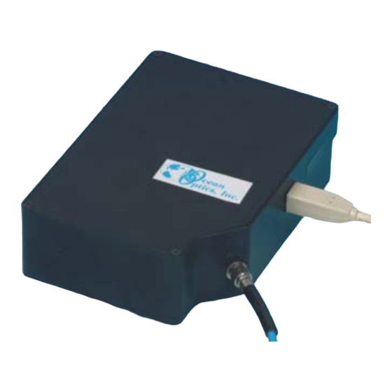
HR2000 Introduction HR2000 Introduction The following chapter contains introductory information about the HR2000 Spectrometer, shipment information, and spectrometer connectivity. Product Overview The HR2000 High-resolution Miniature Fiber Optic Spectrometer provides optical resolution as good as 0.065 nm (FWHM). The HR2000 is responsive from 200-1100 nm, but the specific range and resolution depends on your grating and entrance slit selections. -
Page 6: Eeprom Utilization
HR2000 Introduction EEPROM Utilization An EEPROM memory chip in each HR2000 contains wavelength calibration coefficients, linearity coefficients, and a serial number unique to each individual spectrometer. The OOIBase32 software application reads these values directly from the spectrometer, enabling the ability to “hot-swap” spectrometers between PCs without entering the spectrometer coefficients manually on each PC. -
Page 7: Interface Options
HR2000 Introduction Interface Options The HR2000 has both USB and serial port connectors (with the use of an adapter), enabling you to connect the spectrometer to a desktop or notebook PC via a USB port or to a desktop, notebook, or to a handheld PC via a serial port. -
Page 8: Software And Technical Resources Cd
HR2000 Introduction Software and Technical Resources CD Each order ships with the Ocean Optics Software and Technical Resources CD. This disc contains software, operating instructions, and product information for all Ocean Optics software, spectrometers, and spectroscopic accessories. You will need Adobe Acrobat Reader version 6.0 or higher to view these files. Ocean Optics includes Adobe Acrobat Reader on the Software and Technical Resources CD. -
Page 9: Chapter 2: Hr2000 Specifications
HR2000 Specifications HR2000 Specifications This chapter contains information on spectrometer operation, specifications, and system compatibility. It also includes accessory connector pinout diagrams and pin-specific information. How the HR2000 Works Below is a diagram of how light moves through the optical bench of an HR2000 Spectrometer. The optical bench has no moving parts that can wear or break;... -
Page 10: Hr2000 Specifications Table
HR2000 Specifications HR2000 Specifications Table Ocean Optics permanently secures all components in the HR2000 at the time of manufacture. Only Ocean Optics Technicians can replace interchangeable components, where noted. Item Name Description The SMA Connector secures the input fiber to the spectrometer. Light from the SMA Connector input fiber enters the optical bench through this connector. -
Page 11: Hr2000 Specifications
HR2000 Specifications HR2000 Specifications The following sections provide specification information for the CCD detector in the HR2000, as well as the HR2000 Spectrometer itself. CCD Detector Specifications Detector: Sony ILX511 linear silicon CCD array No. of elements: 2048 pixels Pixel size: 14 µm x 200 µm Pixel well depth: 62,500 electrons... -
Page 12: System Compatibility
HR2000 Specifications System Compatibility The following sections provide information on hardware and software requirements for the HR2000: Compatibility for Desktop or Notebook PCs To use the HR2000, you must have a PC that meets the following minimum requirements: • IBM-compatible PC with Pentium (or higher) processor •... -
Page 13: 20-Pin Accessory Connector Pinout Diagram
HR2000 Specifications 20-Pin Accessory Connector Pinout Diagram When facing the 20-pin Accessory Connector on the HR2000, pin numbering is as follows: Figure 2-3: 20-Pin Accessory Connector Pinout Diagram 20-Pin Accessory Connector – Pin Definitions The following table contains information regarding the function of each pin in the HR2000’s 20-Pin Accessory Connector: Pin # Description... -
Page 14: Chapter 3: Installing The Hr2000
Installing the HR2000 Installing the HR2000 This chapter contains instructions in parallel for connecting the HR2000 via both USB and serial modes. Note: You must install the OOIBase32 software application prior to connecting the HR2000 Spectrometer to the PC. The OOIBase32 software installation installs the drivers required for HR2000 installation. If you do not install OOIBase32 first, the system will not properly recognize the HR2000. -
Page 15: Configuring The Hr2000 In Ooibase32
Installing the HR2000 Configuring the HR2000 in OOIBase32 Once you install the HR2000, you must configure OOIBase32’s Configure Spectrometer options so that OOIBase32 recognizes the HR2000 Spectrometer. Note: Consult the OOIBase32 Spectrometer Operating Software Manual for detailed instructions on configuring the spectrometer in OOIBase32. - Page 16 Installing the HR2000 Configure Hardware Screen - Continued USB Mode Serial Port Mode 1. Specify S2000/PC2000/USB2000/HR2000 in 1. Select the S2000/PC2000/USB2000/HR2000 the Spectrometer Type drop-down menu. option from the Spectrometer Type drop- down menu. 2. Specify HR2000 in the A/D Converter Type drop-down menu.
-
Page 17: Connect Spectroscopic Accessories
Installing the HR2000 Spectrometer Configuration Screen The Spectrometer Configuration screen prompts you to configure specific channel-level spectrometer information, if necessary. Select Spectrometer | Configure | Wavelength Calibration tab from the menu and set system parameters. If you have connected your spectrometer to the PC’s USB port, OOIBase32 pre-fills the coefficients for the HR2000 from information on a memory chip in the spectrometer. -
Page 18: Chapter 4: Troubleshooting
Troubleshooting Troubleshooting The following sections contain information on troubleshooting issues you may encounter when using the HR2000 Spectrometer. Note: For issues encountered when using a handheld PC, consult the OOIPS2000 manual. HR2000 Connected to PC Prior to OOIBase32 Installation If you connect your Ocean Optics USB device to the computer prior to installing your Ocean Optics software application, you may encounter installation issues that you must correct before your Ocean Optics device will operate properly. -
Page 19: Windows 98
Troubleshooting 4. Click the OK button to continue. A warning box appears confirming the removal of the Unknown Device. Click the OK button to confirm the device removal. 5. Disconnect the HR2000 from your computer. 6. Locate the section in this chapter that is appropriate to your operating system and perform the steps in the “Remove Improperly Installed Files”... -
Page 20: Windows 2000/Xp
Troubleshooting Windows 2000/XP: Remove Improperly Installed Files: 1. Open Windows Explorer. 2. Navigate to the Windows | INF directory. If the INF directory is not visible, you will need to disable the “Hide System Files and Folders” option on in Windows Folder Options. Note: If the INF directory is not visible, you will need to disable the “Hide System Files and Folders”... -
Page 21: Troubleshooting The Serial Port Configuration
Troubleshooting Troubleshooting the Serial Port Configuration Occasionally, you may encounter problems with the serial port connection and/or software. Perform the following steps to troubleshoot the serial port connection: 1. Cycle the power on the HR2000 and restart the OOIBase32 software. This ensures that the software and the HR2000 are synchronized. -
Page 22: Chapter 5: Sample Experiments
Sample Experiments Sample Experiments The following sections contain information on conducting sample experiments using the HR2000 and OOIBase32. For information on experiments with OOIPS2000, consult the OOIPS2000 Operating Instructions. Preparing for Experiments Follow the steps below to configure the HR2000 and OOIBase32 for experiments: 1. - Page 23 Sample Experiments Application Tips If the signal you collect is saturating the spectrometer (intensity greater than 4000 counts), you can decrease the light level on scale in scope mode by: • Decreasing the integration time • Attenuating the light going into the spectrometer •...
-
Page 24: Absorbance Experiments
Sample Experiments Absorbance Experiments Absorbance spectra are a measure of how much light a sample absorbs. For most samples, absorbance is linearly related to the concentration of the substance. OOIBase32 calculates absorbance (A ) using the following λ equation… λ λ... - Page 25 Sample Experiments 3. Place a sample of the solvent into a cuvette and take a reference spectrum. You must take a reference spectrum before measuring absorbance. Note: Do not put the sample itself in the path when taking a reference spectrum, only the solvent. Click the Store Reference spectrum icon on the toolbar or select Spectrum | Store Reference from the menu bar to store the reference.
-
Page 26: Transmission Experiments
Sample Experiments Transmission Experiments Transmission is the percentage of energy passing through a sample relative to the amount that passes through the reference. Transmission Mode also displays the portion of light reflected from a sample, since transmission and reflection measurements use the same mathematical calculations. The transmission is expressed as a percentage (%T ) relative to a standard substance (such as air). - Page 27 Sample Experiments 6. Place a sample of the solvent into a cuvette and take a reference spectrum. You must take a reference spectrum before measuring transmission. Note: Do not put the sample itself in the path when taking a reference spectrum, only the solvent. Click the Store Reference spectrum icon on the toolbar or select Spectrum | Store Reference from the menu bar to store the reference.
-
Page 28: Reflection Experiments
Sample Experiments Reflection Experiments Reflection is the return of radiation by a surface, without a change in wavelength. Reflection can be: • Specular (the angle of incidence is equal to the angle of reflection) • Diffuse (the angle of incidence is not equal to the angle of reflection) Every surface returns both specular and diffuse reflections. - Page 29 Sample Experiments Perform the following steps to take reflection measurements using OOIBase32: 1. Place OOIBase32 is in scope mode by clicking the Scope Mode icon on the toolbar, or by selecting Spectrum | Scope Mode from the menu bar. 2. Ensure that the entire signal is on scale. The intensity of the reference signal should peak at about 3500 counts.
-
Page 30: Relative Irradiance Experiments
Sample Experiments Relative Irradiance Experiments Irradiance is the amount of energy at each wavelength emitted from a radiant sample. In relative terms, it is a comparison of the fraction of energy the sample emits and the energy the sampling system collects from a lamp with a blackbody energy distribution (normalized to 1 at the energy maximum). - Page 31 Sample Experiments Perform the following steps to take a relative irradiance measurement using OOIBase32: 1. Place OOIBase32 is in scope mode by clicking the Scope Mode icon on the toolbar, or by selecting Spectrum | Scope Mode from the menu bar. 2.
-
Page 32: Time Acquisition Experiments
Sample Experiments Time Acquisition Experiments OOIBase32 allows you to perform time acquisition experiments. Time acquisition experiments track processes, perform kinetic analyses, and monitor spectral events all as a function of time. You can collect, as a function of time, spectral data from up to six single wavelengths (designated as Channels A through F) and up to two mathematical combinations of these wavelengths (designated as Combinations 1 and 2). - Page 33 Sample Experiments 3. Configure a time acquisition process for a combination of two time channels (if desired) by selecting Combination 1. Perform the steps below to configure a combination: a. Select Enabled to set the time acquisition calculation for the wavelength. b.
- Page 34 Sample Experiments 6. Enable Save Every Acquisition to store data for every spectral acquisition during a time acquisition process (optional). Note: OOIBase32 has options to either store data for each acquisition, or to collect data only after a specified delay. Several factors affect the minimum time acquisition frequency, including integration time, number of spectrometer channels, samples averaged, and computer speed.
-
Page 35: Appendix A: Calibrating The Wavelength Of The Hr2000
Appendix A Appendix A: Calibrating the Wavelength of the HR2000 This Appendix describes how to calibrate the wavelength of your spectrometer. Although each spectrometer is calibrated before it leaves Ocean Optics, the wavelength for all spectrometers will drift slightly as a function of time and environmental conditions. -
Page 36: Calibrating The Wavelength Of The Spectrometer
Appendix A Calibrating the Wavelength of the Spectrometer Perform the steps below to calibrate the wavelength of the spectrometer: 1. Place OOIBase32 into Scope Mode and take a spectrum of your light source. Adjust the integration time (or the A/D conversion frequency) until there are several peaks on the screen that are not off-scale. 2. - Page 37 Appendix A 5. Use the spreadsheet or calculator to calculate the wavelength calibration coefficients. In the spreadsheet program, find the functions to perform linear regressions. • If using Quattro Pro, look under Tools | Advanced Math • If using Excel, look under Analysis ToolPak 6.
-
Page 38: Saving The New Calibration Coefficients: Usb Mode
Appendix A Saving the New Calibration Coefficients: USB Mode Ocean Optics programs wavelength calibration coefficients unique to each HR2000 onto an EEPROM memory chip in the HR2000. You can overwrite old calibration coefficients on the EEPROM if you are using the HR2000 via the USB port. If you are using the HR2000 via the serial port, consult the Saving the New Calibration Coefficients: Serial Mode section later in this Appendix. -
Page 39: Saving The New Calibration Coefficients: Serial Mode
Appendix A Saving the New Calibration Coefficients: Serial Mode If you are connecting the HR2000 Spectrometer to the serial port of the PC, you need to save the new wavelength calibration coefficients to the .SPEC file that OOIBase32 accesses when opened. Note: You cannot save the calibration coefficients to the EEPROM memory chip on the HR2000 when using the serial mode. -
Page 40: Appendix B: Hr2000Cg-Uv-Nir Spectrometer
Appendix B Appendix B: HR2000CG-UV-NIR Spectrometer The HR2000CG-UV-NIR Composite Grating Spectrometer has a new proprietary grating and order-sorting filter to provide a 200-1100 nm wavelength range with 1.0 nm optical resolution in one spectrometer. The HR2000-CG-UV-NIR is functionally similar to the standard HR2000 Spectrometer. Follow the instructions in Chapter 3 to configure the HR2000CG-UV-NIR. -
Page 41: Index
Index Accessories, 2, 13 L2 Detector Collection Lens, 6 Accessory Connector, 8 Lens, 6 Diagram, 9 Pin Definitions, 9 Pinout, 8 memory chip, 2 Adobe Acrobat Reader, 4 Mirror, 6 Calibrating, 31 OOIBase32, 11 CCD, 7 Options CCD Detector, 6 Interface, 3 Compatibility, 8 Overview, 1... - Page 42 Wavelength Calibration, 31 Wavelength Calibration Data File, 3 Wavelength Calibration Data Sheet, 3 HR2000 High-Resolution Fiber Optic Spectrometer...
Need help?
Do you have a question about the Ocean Optics HR2000 Series and is the answer not in the manual?
Questions and answers