
Related Manuals for Halma ALICAT M


Summary of Contents for Halma ALICAT M
- Page 1 OPERATING MANUAL FOR STANDARD FLOW AND PRESSURE DEVICES Models M · MC · P · PC · L · LC...
- Page 2 Thank you for purchasing your Alicat instrument. If you have any questions, or if something is not working as expected, please contact us. We are eager to help you in any way possible. Contact Information MC-10SLPM World Headquarters, Europe Tucson, Arizona, USA europe@alicat.com info@alicat.com Geograaf 24...
-
Page 3: Introduction
Introduction M-100SLPM Depending on the model, Alicat instruments have a variety of innovative features: • 1000 readings per second guarantees high resolution data. • High-accuracy performance for all your flow. Use the mass flow instruments with any of the 98+ gases included with Gas Select™... -
Page 4: Table Of Contents
Contents Introduction Instrument Setup Quick Start Guide Gas Selection Mass Flow Instruments Installation and Startup Gas Select™ Safety Warnings COMPOSER™ Gas Mixes Installation Creating New Mixes in COMPOSER™ Filters Viewing, Deleting, and Creating Similar Mixes Power and Signal Connections Sensor Setup Analog Signals Engineering Units Option: Charging a Portable Meter or Gauge... - Page 5 Appendix A: Pinouts 8-Pin Mini-DIN (Default) Locking Industrial Connector Pinout 9-Pin D-Sub Connector Common Pinouts 15-Pin D-Sub Connector Common Pinouts M12 Connector Common Pinouts Appendix B: Reference Information Engineering Units Gas List by Number Gas List by Category Appendix C: Application Setup MCV Controller Operating Notes Pressure Controller Applications Forward (Downstream) Pressure Control...
-
Page 6: Quick Start Guide
Quick Start Guide Setup • Connect your instrument. Ensure that flow passes through your instrument in the same direction as the arrow on This MC-1SLPM-D model mass flow controller is a typical unit. the flow body (usually left to right). The flow body and the valve Application setup examples can be sizes can vary significantly. -
Page 7: Installation And Startup
Installation and Startup Safety Warnings • For assistance in performing any disassembly • Operating this instrument under conditions of the instrument, please contact Alicat which exceed the specifications noted in support (page 2) for assistance. the manual or specification sheet could lead to equipment damage or injury. -
Page 8: Filters
Filters When pressure drop is not a concern, use in-line sintered Liquid: filters to prevent large particulates from entering the flow • 20 microns for instruments with body of the controller. Suggested maximum particulate flow ranges ≤100 CCM. sizes are as follows: •... -
Page 9: Analog Signals
Analog Signals Using Ground to Tare (Meters and Gauges) You can tare your meter or gauge remotely by momentarily Primary Analog Output Signal grounding the remote tare pin (pin 4 on the Mini-DIN Most instruments include a primary analog output signal connector). - Page 10 Bleed Ports Liquid Instruments Liquid instruments include bleed ports (8-32 Nylon-tipped screw) on the front for the removal of air bubbles. ✓ Note: A small amount of liquid will leak from the instrument during this procedure. Take necessary precautions to prevent damage to anything nearby. Bleed both of the ports as follows: 1.
-
Page 11: Basic Operations
Basic Operations This section covers your instrument's most common functions. Settings for more specialized needs can be found after this section. Some information found in this section may be repeated in other sections for ease of section navigation. Viewing Live Data The display screen has a number of options for displaying live data. -
Page 12: Taring The Instrument
Taring the Instrument Taring is an impor tant practice that ensures your instrument provides its most accurate measurements. This function gives a zero reference point for measurements. For instruments installed with a barometer, the absolute pressure reading can be tared when venting to the local barometric pressure. -
Page 13: Selecting Gas Mass Flow Instruments
Selecting Gas Mass Flow Instruments → → MENU SETUP Active Gas In most cases, mass flow instruments are physically calibrated at the factory using air. Gas Select™ allows you to reconfigure the instrument to flow a different gas without any need to send it back for a physical recalibration. -
Page 14: Data Screens
Data Screens Depending on the instrument, there can be up to four screens providing different information based on your needs. Further settings for the data screens can be found on page Live Screen The Live screen is the default data screen of the instrument. -
Page 15: Option: Color Tft Display
Option: Color TFT Display Instruments ordered with a color display are functionally the same as standard backlit monochrome instruments. The color enables additional on-screen information. Multi-Color Display Indicators • GREEN: Parameter labels and adjustments associated with the button directly above or below the label are presented in green. -
Page 16: Instrument Information
Instrument Information → ABOUT MENU ABOUT menu ( ) contains information for setup, configuration, and troubleshooting. Basic Instrument Information → → MENU ABOUT About Device This includes information on the following: MODEL • : Instrument model (character limited—part number may be truncated) SERIAL NO •... -
Page 17: Process Control Controllers
Process Control Controllers For a controller to regulate the flow or pressure, it needs to have a setpoint established. The setpoint is the amount of flow or the pressure that the controller attempts to achieve in a process. Setpoint Control menu →... -
Page 18: Idle Connection Response
Idle Connection Response → → → MENU CONTROL Setpoint Setup On Comm Timeout If the communication connection is timed out, the controller can either set a zero setpoint, or maintain the last setpoint given. The timeout time is infinite by default and can be manually defined (page 30). -
Page 19: Ramping Options
Ramping Options Ramping options control when ramping occurs. This can be when the setpoint changes, when the instrument powers on, or when setting a zero setpoint. Ramp Up • can toggle between on and off. When off, the ramp rate will not be honored when increasing flow or pressure to reach a given setpoint. -
Page 20: Repeat A Batch
→ BATCH Repeat a Batch • To remove a batch setting, press → → → CLEAR REMAIN CLEAR SET. RESET • For an identical batch, press . Flow begins Deleting the batch does not affect the setpoint. immediately. Flow will continue at the setpoint rate. BATCH •... -
Page 21: Optimize Control (Autotune)
Optimize Control (Autotune) Flow Controllers → → MENU CONTROL Optimize Control Alicat instruments are set up at the factory to perform well over a range of expected conditions. If conditions change dramatically, or if the instrument needs to perform in a very specific way, then it may be beneficial to optimize the response. -
Page 22: Control Loop
• MOST VERSATILE: accommodates an even wider Max Flow range of conditions, but with slower response time. This setting limits the maximum flow during autotuning to protect delicate processes. In unusual circumstances • GOAL: enables advanced users to achieve a the maximum flow may still be exceeded;... -
Page 23: Flow Limit While Controlling Pressure Flow Controllers
Limiter Gain Tuning the PD²I Control Algorithm 3. Set the to 500 and adjust as needed. Limiter Gain determines how aggressively the I usually provides a faster response in dual-valve flow proportional control function corrects the error when and pressure controllers. This algorithm uses typical PI terms and adds a squared derivative term (D): the flow rate exceeds the maximum flow setting. -
Page 24: Control Deadband For Pressure Control
Gas Adjust Mass Flow Controllers → → → MENU CONTROL Control Loop Gas Adjust Enabling Gas Adjust will change the control loop gains to keep the control response time more consistent as the gas is changed. Choose to enable the feature, Until Set Gain disable, or to use gas adjust to get more... -
Page 25: Instrument Setup
Instrument Setup Gas Selection Mass Flow Instruments Your mass flow instrument was physically calibrated at the factory using air. Gas Select™ allows you to reconfigure the instrument to flow a different gas without any need to send it back for a physical recalibration. The instrument can also be programmed to measure custom gas mixtures. -
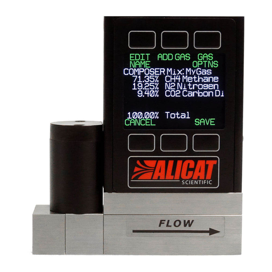
Page 26: Creating New Mixes In Composer
Creating New Mixes in COMPOSER™ → → → → MENU SETUP Active Gas COMPOSER Mixes Create Mix Give the Mix a Short and Long Name DOWN changes the character. Valid characters include . , - CANCEL A–Z, 0–9, punctuation ( ), and space. -
Page 27: Totalizer Options Flow Instruments
Totalizer Options Flow Instruments The totalizers measure the total flow over a given time. The current total values are shown in the Totalizer data screens (page 14). Totalize Type → → → → MENU SETUP Sensor Totalizer → Totalizer 1 or Totalizer 2 Totalize Select whether to totalize Mass Flow or Volumetric Flow. -
Page 28: Stp/Ntp Reference Values Mass Flow Instruments
Totalizer Limit There are 4 options for how the totalizer reacts when it reaches its limit: • Set to Zero: Totalizer resets and continues counting from zero once the maximum count is reached. No error status is displayed. • Zero and Set OVR: Totalizer resets to zero and continues once the maximum count is reached. -
Page 29: Flow And Pressure Averaging
Reference options: Stan T • : Standard Temperature Stan P • : Standard Pressure Norm T • : Normal Temperature Norm P • : Normal Pressure Ref temp units • changes the temperature units used for STP and NTP values Ref pressure units •... -
Page 30: Baud Rate
Baud Rate Manage Setpoint when Connection is Idle → → SETUP RS-232 Serial or RS-485 Serial Baud Rate Controllers → → MENU SETUP RS-232 Serial Baud rate is the speed at which digital instruments transfer → or RS-485 Serial Idle: information over a serial connection. -
Page 31: Screen Lighting
Show Actions Menu this option is set to , an option to • Multi-variable: Screen that resembles change that parameter’s engineering units is shown, the live screen (page 11). as well as an option to highlight the parameter. Screen Lighting Show Valve Drive •... -
Page 32: Digital Control
Digital Control Alicat instruments can be operated using Alicat FlowVision™ 2.0 software, ASCII serial commands, or MODBUS RTU protocol. • FlowVision 2.0: page 32 • Serial ASCII Communication: page 33 • MODBUS RTU: page 39 FlowVision 2.0 FlowVision™ 2.0 is Windows-based software that enables easy collection and analysis of data from Alicat controllers and meters. -
Page 33: Serial Ascii Communication
Serial ASCII Communication Alicat’s Serial Terminal is a pre-configured program for serial communication via the instrument’s serial connector. Download Serial Terminal for free at alicat.com/drivers. Terminal is also available within FlowVision 2.0 (page 32). The section below outlines several common commands. Many more commands are available. For more detailed information please see the Serial Primer manual at alicat.com/manuals. -
Page 34: Collecting Data
unit_id V Tare the flow: Example: AV (sets flow reading to zero) Taring a gauge or differential pressure sensor must be performed when the instrument is open to atmosphere. unit_id P Tare the pressure: Example: AP For instruments equipped with a barometer, the second tare aligns the internal absolute pressure sensor with the current barometer reading and must be done with the instrument open to atmosphere: unit_id... -
Page 35: Data Format
Data Format unit_id Collect live data by typing the command or by setting your instrument to streaming. Each line of data for live measurements appear in the format below. The measurements present are dictated by the type of instrument. Meters and gauges do not show a setpoint. -
Page 36: Optimize Control (Autotune) Flow Controllers
Following the operation, the instrument will return: unit _ id termination notes overshoot delaymsec timeconstantMsec risetimemsec bandwidthhz where termination is 0 for normal operation; 1 if the operation was aborted manually; or, 2 if aborted due to oscillation. notes are observations on reliability of the results. Values in the following table may be added for a single collection. Value Notes The process data showed typical patterns. -
Page 37: Gas Select™ And Composer™ Mass Flow Instruments
unit_id speed_mode goal_time algorithm Optimize Flow: LCTCS Example: A LCTCS 3 (optimize using the FAST speed mode) where speed_mode determines how the function will address the tradeoff between speed and the ability to handle a range of process variability. -
Page 38: Quick Command Reference
Defining a new COMPOSER™ gas mix is faster using serial commands than using the front panel. The basic formula for this is: unit_id mix_name mix_number gas1_% gas1_number gas2_% gas2_number... mix_name Use a maximum of 6 letters (upper and/or lower case), numbers and symbols (period or hyphen only). This is equivalent to the short name when creating a mix via the front panel (page 25). -
Page 39: Modbus Rtu Communication
MODBUS RTU Communication MODBUS is an application-layer messaging protocol that formats data for communications over serial RS-232 or RS-485. The instrument supports MODBUS RTU protocol, with data transmitted through Pin 3 of the DB9 connector. MODBUS RTU can be used to control: •... -
Page 40: Troubleshooting
Troubleshooting If you run into trouble with installation or operation, get in touch with support (page General Use Issue: The buttons do not work, and the screen shows Issue: I dropped my instrument. Is it OK? Do I need to recalibrate? Action: The flow controller buttons were locked out via a serial Action: If it turns on and appears to respond normally, then it is unit_id... - Page 41 Pressure Readings Issue: My pressure readings are negative. Action: If a negative reading is not expected, your instrument may need to be tared ( ). Ensure a gauge pressure sensor (or an absolute page 12 pressure sensor with an optional barometer) is open to the ambient atmosphere before taring. A differential pressure sensor should be exposed to a common pressure on both ports before taring.
-
Page 42: Maintenance
Maintenance Warning: Do not attempt to disconnect this instrument from any system which has been pressurized without independently confirming that all pressure has been safely released and that any hazardous gases which remain in that system have been purged. Cleaning Mass flow and pressure instruments do not require cleaning, provided that they flow clean, dry gas. -
Page 43: Appendix A: Pinouts
Appendix A: Pinouts Check the calibration data sheet and pinout for your instrument. page 33 for additional important information about connecting your instrument to a computer for serial commands. Individual pinouts available at alicat.com/pinout. The availability of different output signals depend on the options ordered. Female Connector Male Connector Male Connector... -
Page 44: 9-Pin D-Sub Connector Common Pinouts
9-Pin D-Sub Connector Common Pinouts Female Connector Male Connector DB9 (F) DB9A DB9M (M) and DB9K DB9R DB9T DB9U DB9B DB9G DB9H DB9I DB9N Analog Current NC TX or A TX or A RX or B Analog Out 2 RX or B TX or A Power In Analog Out 2... -
Page 45: M12 Connector Common Pinouts
M12 Connector Common Pinouts Female Connector Male Connector M12MD Optional: 1–5 or 0–10 Vdc Optional: 4–20 mA primary output signal 0–5 Vdc Output Signal Not Connected Power In Static 5.12 Vdc Optional: Secondary analog output (4–20 mA, 0–5 Vdc, 1–5 Vdc, 0–10 Vdc) or basic alarm Serial RS-232 RX (receive input) / RS-485(-) Serial RS-232 RX (receive input) / RS-485(-) Analog Setpoint Input (Controllers) -
Page 46: Appendix B: Reference Information
Appendix B: Reference Information Engineering Units For more information on engineering units, see the engineering units section (page 26). Flow Units Pressure Units Volumetric Standard Normal Notes Absolute or Gauge Notes Barometric µL∕m SµL∕m NµL∕m Microliter per minute‡ Pascal mL∕s SmL∕s NmL∕s Milliliter per second... -
Page 47: Gas List By Number
Gas List by Number To use any of these gases in your instrument, use Gas Select™ (page 25). Short Name Long Name Short Name Long Name Short Name Long Name Air (Clean Dry) R-125 Pentafluoroethane (CF3CHF2)2 ³ HeOx80 80% O2, 20% He Argon HeOx99 99% O2, 1% He... -
Page 48: Gas List By Category
Gas List by Category See previous page for Gas Select™ index numbers. Pure Non-Corrosive Gases Welding Gases Synthesis Gases Acetylene (C2H2) 40% H2, 29% CO, 20% CO2, 11% CH4 Air (clean, dry) 64% H2, 28% CO, 1.0% CO2, 7.0 CH4 Argon (Ar) C-10 70% H2, 4.0% CO, 25% CO2, 1.0% CH4... -
Page 49: Appendix C: Application Setup
Appendix C: Application Setup MCV Controller Operating Notes Alicat’s MCV mass flow controller is equipped with an integrated Swagelok positive shutoff valve. This valve is ® normally closed, but can be opened by supplying 60–120 60 120 Three-way PSIG of air pressure. The shut-off valve closes again when PSIG solenoid valve this pressure is reduced below 60 PSIG. -
Page 50: Back Pressure Control
Back Pressure Control When the valve is located on the downstream side (inverse control), the sensor controls pressure upstream. This configuration is referred to as a back pressure controller. This configuration follows our inverse pressure control algorithm. The valve closes to increase pressure, and opens to decrease pressure. Note: Back pressure controllers include “DS,”... -
Page 51: Remote-Sensing Controller
Remote-Sensing Controller The PC3-Series senses and controls the pressure at a point in the system outside of the pressure controller itself. All PC-Series controllers can be ordered with an additional NPT port that connects to the pressure sensor in the device. The pressure sensor is isolated from the flow path within the device.
Need help?
Do you have a question about the ALICAT M and is the answer not in the manual?
Questions and answers