Table of Contents
Advertisement
Quick Links
Advertisement
Table of Contents

Related Manuals for Halma ALICAT BC Series


Summary of Contents for Halma ALICAT BC Series
- Page 1 OPERATING MANUAL FOR MASS FLOW INSTRUMENTS BASIS 2 METERS AND CONTROLLERS...
-
Page 2: Contact Information
Thank you for purchasing your mass flow BASIS 2 GAS MASS instrument. FLOW INSTRUMENTS If you have any questions, or if something is not working as expected, please contact us. We are eager to help you in any way possible. Contact Information World Headquarters, Europe... -
Page 3: Introduction
Introduction Your new BASIS 2 B- or BC-Series instrument is a highly accurate mass flow device that you can control through several digital communication methods or through analog signals. Log data to your PC with a serial data connection to control the instrument and to store flow data. This manual covers the following instruments: •... -
Page 4: Table Of Contents
Contents Contact Information MODBUS-RTU Calibration Communicating Via MODBUS-RTU MODBUS Address Introduction Changing the Baud Rate Setpoint Type Getting Started Changing the Setpoint Mounting Communication Watchdog Filters Taring the Instrument Flow Averaging Gas Connections Totalizer Maximum Pressure Batch Dispensing Power and Signal Connections Changing the Gas Control Switch Command Protocol... -
Page 5: Getting Started
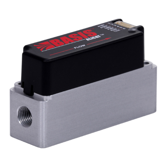
Getting Started The major instrument components are shown in the diagram below. Most communication with the instrument is completed through digital communication or analog signals, as described later in this manual. The LED on the top of the instrument provides the following feedback: •... -
Page 6: Filters
Filters When pressure drop is not a concern, use in-line sintered filters to prevent large particulates from entering the flow body of the controller. Suggested maximum particulate size is 50 microns for all flow ranges. Gas Connections BASIS 2 series instruments do not require straight runs of pipe upstream or downstream. Instruments are shipped with plastic plugs seated in the processing ports. - Page 7 Function Analog Setpoint Input Analog Signal Output Ground Power In, 12–24V Serial RS-232 (Rx) or RS-485 B (+) Serial RS-232 (Tx) or RS-485 A (-) Getting Started...
-
Page 8: Control
Control BASIS 2 Series controllers and meters can be operated using digital or analog communication. Digital communication can be performed using Alicat FlowVision™ 2.0 software, ASCII serial commands, MODBUS-RTU, or analog signals. • FlowVision 2.0: page 8 • ASCII Serial Communication: page 10 •... - Page 9 Note that the following three controls differ from the FlowVision manual for BASIS 2: 1. Valve drive. The “Valve” button has the following options: a. Open/exhaust b. Close c. Direct drive (sets the "Setpoint" entry field to use a percentage instead of a unit of measure) d.
-
Page 10: Alicat Ascii Serial Communication
Alicat ASCII Serial Communication Alicat ASCII Serial Terminal is a pre-configured program for serial communications via the instrument’s 6-pin connector. Download Serial Terminal for free at alicat.com/drivers. Serial commands are not case-sensitive. In the descriptions below, however, the commands are shown in uppercase while command variables are shown in lowercase to help differentiate them. -
Page 11: Query Full Data Frame
Note: Valve thermal management activates if a setpoint is given for a certain amount of time with no flow detected. To prevent the valve from getting excessively hot when driven fully, thermal management is activated, which pulses the valve open/closed until a change in flow is detected. -
Page 12: Maximum Setpoint Ramp Rate
Value Notes The analog input is used as the setpoint source. Digital setpoint commands are not accepted. Saved digital. Digital setpoint commands are accepted; the most recent command will be used when the instrument is powered up. The analog input is disconnected from the setpoint. -
Page 13: Hold Valve Position / Resume Flow
Example: aWD 10 (create a watchdog with 10 ms timeout for instrument A) To disable the watchdog: unit_idWD 0 Hold Valve Position / Resume Flow The controller valve can be held at any percentage of full drive (controllers only). To hold the valve at a particular drive percentage: unit_idHPUR valve_drive... -
Page 14: Start A Measurement
Mode Description Begin a new measurement when the digital setpoint is changed. Begin a new measurement when the valve is being held and the hold percentage is changed. Begin a new measurement when the average flow of the last measurement is read. The table values may be added together to trigger measurements based on multiple methods (the value must be an integer between 0 and 7). -
Page 15: Autotare
To tare the instrument: unit_idV duration duration is the time in milliseconds, to collect values for calculating the tare offset. The value is a positive integer from 1–32767. Example: aV 1000 (tares instrument A, with the offset calculated over 1 second) Autotare If autotare is enabled (controllers only), the instrument will automatically zero its measurement after being at a 0 setpoint for 2 seconds. -
Page 16: Totalizer Configuration
Example: aTB 200 (set the batch volume to 200 [volume units] for instrument A) Totalizer Configuration unit_idTC To read the current totalizer configuration: To set the current totalizer configuration: unit_idTC limit_mode limit_mode is the action when the totalizer reaches the maximum allowed value: Value Description Keep totalizer value at the maximum value and do not indicate an OVR error. -
Page 17: Serial Baud Rate
unit_idMA To read the MODBUS address: To set the MODBUS address: unit_idMA address address is the new MODBUS address, an integer from 1–247. Serial Baud Rate unit_idNCB To read the current baud rate: To set the baud rate: unit_idNCB baud_rate baud_rate is the communication rate, per the table below: Value... -
Page 18: Modbus-Rtu
MODBUS-RTU MODBUS is an application-layer messaging protocol that formats data for communications over serial RS-232 or RS-485. The instrument supports MODBUS-RTU protocol, with data transmitted through Pin 6 of the 6-pin connector. MODBUS-RTU can be used to control: • taring •... -
Page 19: Setpoint Type
To read the current baud rate: read register 21. To change the baud rate: write a value from the table above to register 21. Note: When changing the instrument’s baud rate, the baud rate for the COM port must change in time to successfully receive the response confirming the new baud rate. -
Page 20: Flow Averaging
automatically when the setpoint had been set to 0 for at least two seconds. To disable autotare (controllers only): write 0 to register 515. Flow Averaging Flow averaging governs how the flow sensor reports data, an integer 0–2500 ms. A higher flow averaging setting will smooth the data, which can be useful for rapidly fluctuating flow readings. -
Page 21: User Registers
0 indicates that the instrument is in BASIS 2 Protocol mode. 1 indicates that the instrument is in BASIS 1 Protocol mode. To set the command protocol: write 0 or 1 to register 56. ∆ Caution: The BASIS 1 protocol only works with flow units of SCCM, SLPM, NCCM, and NLPM. -
Page 22: Measurement Data Registers
2108-2109 The volume remaining for the current batch, an integer in the current totalizer volume units with the same scaling as the total volume, registers 2104-2105. Added in V3.0.0. 33524 The commanded setpoint, an integer 0–4095. Values less than 4 will be set to 0. Values greater than 4095 will be set to 4095. This value is ignored if the setpoint source is analog. - Page 23 4205 The maximum flow measured of the current, or most recent measurement, a signed 2-byte integer. Flow is equal to the value after formatting with the factory-set number of decimal places. This value will not be accurate if flow range, units, gas, or calibration has been changed.
-
Page 24: Configuration And Function Registers
Configuration and Function Registers These registers affect the operation of the instrument. Data Address Notes The baud rate: 0: 4800 1: 9600 2: 19200 3: 38400 4: 57600 Added in V2.2.2. 5: 115200 Added in V2.2.2. The firmware version. If the version is Va.b.c, it is encoded as 256*a + 16*b + c. - Page 25 The units of measure for flow: 0: SCCM 1: NCCM 2: SLPM 3: NLPM 4: SmL/s 5: NmL/s 6: SmL/m 7: NmL/m 8: SL/h 9: NL/h 10: SCCS 11: NCCS 12: Sm³/h 13: Nm³/h 14: Sm³/d 15: Nm³/d 16: SCIM 17: SCFM 18: SCFH 19: SCFD...
- Page 26 Indicates if instrument is in BASIS 1 Protocol mode. 0: Instrument is in BASIS 2 Protocol mode 1: Instrument is in BASIS 1 Protocol mode Added in V3.0.0. Write 0x5214 (21012) to restore factory settings. The valve control mode, an integer (controllers only): 0: Normal closed loop flow control Nonzero: Exhaust/Hold for purge mode;...
- Page 27 The integral control gain in the PDF control algorithm (controllers only) This is an integer 0–65535. Note that this register is scaled differently from legacy integral gain registers. Added in V2.4.0. 521–522 Desired volume for the current totalizer batch (controllers only) This is an integer in the current instrument total volume units, indicated in register 49 and scale, formatted with the factory-set number of decimals.
-
Page 28: Analog Signals
Analog Signals Alternatively to the digital communications methods described above, the instrument can be controlled using analog signals transmitted through the 6-pin connector. Warning: Do not supply power to the instrument until all necessary pins have been properly connected. Function Analog Setpoint Input Analog Signal Output Ground... -
Page 29: Troubleshooting
Troubleshooting If you run into trouble with installation or operation, get in touch with support (see page Issue: The analog output signal indicates values lower than expected. Action: Analog signal voltage degrades over long distances. You can minimize this effect by using wires with a heavier gauge, especially in the ground wire. -
Page 30: Maintenance
Maintenance Cleaning This instrument requires minimal maintenance. If necessary, the outside of the instrument can be cleaned with a soft dry cloth. Avoid excess moisture or solvents. The single most important thing that affects instrument life and accuracy is the quality of the gas being measured. -
Page 31: Reference
Reference Engineering Units Flow Units Standard Normal Notes SmL∕s NmL∕s Milliliter per second SmL∕m NmL∕m Milliliter per minute SLPM NLPM Liter per minute SL∕h NL∕h Liter per hour SCCS NCCS Cubic centimeter per second SCCM NCCM Cubic centimeter per minute Sm3∕h Nm3∕h Cubic meter per hour...
Need help?
Do you have a question about the ALICAT BC Series and is the answer not in the manual?
Questions and answers