
Related Manuals for TeraBee IND-TOF-1


Summary of Contents for TeraBee IND-TOF-1
- Page 1 User Manual for Terabee IND-TOF-1 Technical support: terabee.com/support/ Sales and commercial support: terabee-sales@terabee.com...
-
Page 2: Table Of Contents
Table of contents 1. Introduction 1.1. About Terabee IND-TOF-1 1.2. Technical specifications 1.3. Symbols explanation 2. Package contents 3. Mechanical integration 3.1. Mechanical design and mounting 3.2. Operating buttons and indicators 3.3. M12 connector pinout 3.4. DC Electrical characteristics 4. Operating modes 4.1. -
Page 3: Operating Mode
6.2. Field of View characteristics 7. Connection example: input to a PLC 7.1. PNP connection 7.2. NPN connection 8. Compliance Copyright © Terabee 2023 Terabee, 90 rue Henri Fabre Terabee IND-TOF-1 01630 Saint-Genis-Pouilly, France (next to CERN) User manual 3/48... -
Page 4: Introduction
The purpose of this document is to give guidelines for installation, use and integration of the Terabee IND-TOF-1 distance sensor. The user manual includes instructions on the six modes: setup and operation. For guidelines on sensor connection and usage with a... -
Page 5: Technical Specifications
1.2. Technical specifications Table 1 - Technical specifications of Terabee IND-TOF 1 Product code TB-IND-TOF-1-RS485 Performance Detection principle Infrared Time-of-Flight Range 0.5 m to 12.5 m Output resolution 5 mm Accuracy ±4 cm in the first 4 m, ±1% beyond 4 m Repeatability ±5 mm... -
Page 6: Symbols Explanation
The following symbols are used within the document: This symbol indicates specific recommendations in order to run the sensor in the intended way Copyright © Terabee 2023 Terabee, 90 rue Henri Fabre Terabee IND-TOF-1 01630 Saint-Genis-Pouilly, France (next to CERN) User manual... -
Page 7: Package Contents
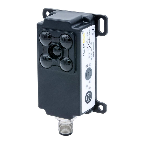
2. Package contents The product package (Figure 2) contains the following items: ● Terabee IND-TOF-1 distance sensor Figure 2. Product package content Copyright © Terabee 2023 Terabee, 90 rue Henri Fabre Terabee IND-TOF-1 01630 Saint-Genis-Pouilly, France (next to CERN) User manual... -
Page 8: Mechanical Integration
3. Mechanical integration 3.1. Mechanical design and mounting Terabee IND-TOF-1 distance sensor offers an ABS housing and an aluminium backplate (part of sensor housing) for robust mounting. Figure 3 illustrates external dimensions of the distance sensor. Figure 3. External dimensions of Terabee IND-TOF-1 The bottom casing part includes four slots for mounting the sensor using standard M4 screws. - Page 9 An optional 90 degree mounting bracket accessory is also available on the Terabee website for angled attachment methods to existing industrial infrastructures. Copyright © Terabee 2023 Terabee, 90 rue Henri Fabre Terabee IND-TOF-1 01630 Saint-Genis-Pouilly, France (next to CERN) User manual...
- Page 10 ● It is better to avoid having other sources of continuous wave or modulated IR light close to the sensor Copyright © Terabee 2023 Terabee, 90 rue Henri Fabre Terabee IND-TOF-1 01630 Saint-Genis-Pouilly, France (next to CERN) User manual...
-
Page 11: Operating Buttons And Indicators
LED indicator Power indicator LED indicator Notification on device selection by master LED indicators Th1, Th2 Error and threshold breach notification Copyright © Terabee 2023 Terabee, 90 rue Henri Fabre Terabee IND-TOF-1 01630 Saint-Genis-Pouilly, France (next to CERN) User manual 11/48... -
Page 12: M12 Connector Pinout
Th1, Th2 Green/Red Distance threshold breach notification, error indication 3.3. M12 connector pinout Terabee IND-TOF-1 uses an M12 A-coded male connector, 5 pins. Figure 7 Table 4 provides an overview of the connector pinout. Figure 7. M12, 5-pin connector pinout layout... -
Page 13: Dc Electrical Characteristics
50 mA 70 mA 90 mA Voltage output DC 24 V Digital output levels NO/NC (in PNP/NPN) Current consumption 450 mA Copyright © Terabee 2023 Terabee, 90 rue Henri Fabre Terabee IND-TOF-1 01630 Saint-Genis-Pouilly, France (next to CERN) User manual 13/48... -
Page 14: Operating Modes
Mode 6 requires no setup and offers no switching output, and distance data sampling is started as soon as the sensor is powered. Copyright © Terabee 2023 Terabee, 90 rue Henri Fabre Terabee IND-TOF-1 01630 Saint-Genis-Pouilly, France (next to CERN) User manual... - Page 15 (Modbus) The sensor is not triggered while the light beam in the trigger zone is broken (applicable to modes 2, 4 and 5) Copyright © Terabee 2023 Terabee, 90 rue Henri Fabre Terabee IND-TOF-1 01630 Saint-Genis-Pouilly, France (next to CERN)
-
Page 16: Sensor Setup Phases
A background threshold is programmed to set the trigger zone. Mode 1 is useful for alarm applications, positioning tasks and monitoring distance. Copyright © Terabee 2023 Terabee, 90 rue Henri Fabre Terabee IND-TOF-1 01630 Saint-Genis-Pouilly, France (next to CERN) User manual... -
Page 17: Set Up
(e.g wall) is covering the sensors entire Field of View, no further than the maximum range (12.5 meters) of the sensor. Copyright © Terabee 2023 Terabee, 90 rue Henri Fabre Terabee IND-TOF-1 01630 Saint-Genis-Pouilly, France (next to CERN) -
Page 18: Operation
LEDs will stay RED as long as the object is in the Field of View Copyright © Terabee 2023 Terabee, 90 rue Henri Fabre Terabee IND-TOF-1 01630 Saint-Genis-Pouilly, France (next to CERN) User manual 18/48... -
Page 19: Description
Step 2 - Sensor ready ● The background is now taught in and the sensor is in operation mode. Copyright © Terabee 2023 Terabee, 90 rue Henri Fabre Terabee IND-TOF-1 01630 Saint-Genis-Pouilly, France (next to CERN) User manual... -
Page 20: Operation
NO/NC switching output. Please refer to Section 5.2.2. for additional information. Copyright © Terabee 2023 Terabee, 90 rue Henri Fabre Terabee IND-TOF-1 01630 Saint-Genis-Pouilly, France (next to CERN) User manual 20/48... -
Page 21: Led Signalization Sequence
Obstacles that partially enter the sensors Field of View may be detected at an incorrect distance, caused by an averaging effect (refer to Section 6.2.) Copyright © Terabee 2023 Terabee, 90 rue Henri Fabre Terabee IND-TOF-1 01630 Saint-Genis-Pouilly, France (next to CERN) User manual 21/48... -
Page 22: Set Up
● Once both thresholds are registered, the sensor will go into “Time delay for Operation mode” for 2 seconds (default), before initializing operation mode. LED Copyright © Terabee 2023 Terabee, 90 rue Henri Fabre Terabee IND-TOF-1 01630 Saint-Genis-Pouilly, France (next to CERN) -
Page 23: Operation
Figure 14. Mode 3 operation for NO/NC Active region = 0 (default value) ⇒ Only white patched area (Th1 < distance < Th2) is triggering the switching output Copyright © Terabee 2023 Terabee, 90 rue Henri Fabre Terabee IND-TOF-1 01630 Saint-Genis-Pouilly, France (next to CERN) - Page 24 ON / RED and the Background threshold Greater than or at Th1 and Th2 stay background threshold continuously ON / distance GREEN Copyright © Terabee 2023 Terabee, 90 rue Henri Fabre Terabee IND-TOF-1 01630 Saint-Genis-Pouilly, France (next to CERN) User manual 24/48...
-
Page 25: Led Signalization Sequence
This mode is used for object or vehicle height monitoring as well as object sorting for size. 4.6.2. Set up Figure 16. Mode 4 setup phases. Copyright © Terabee 2023 Terabee, 90 rue Henri Fabre Terabee IND-TOF-1 01630 Saint-Genis-Pouilly, France (next to CERN) User manual 25/48... -
Page 26: Operation
(the measured distance corresponds to the background threshold distance), the switching output is activated. The LEDs will also signal accordingly. Copyright © Terabee 2023 Terabee, 90 rue Henri Fabre Terabee IND-TOF-1 01630 Saint-Genis-Pouilly, France (next to CERN) User manual... - Page 27 The following table summarizes possible detection outcomes for mode 4. Table 11 - NO/NC active region in mode 4 Location of detection LED indication / Switching Switching Copyright © Terabee 2023 Terabee, 90 rue Henri Fabre Terabee IND-TOF-1 01630 Saint-Genis-Pouilly, France (next to CERN) User manual 27/48...
-
Page 28: Rolling Buffer (5 Measurements)
(GREEN) Th1; Th2 LEDs stay Indicates that setup is finalized and sensor continuously ON is in operation mode. (GREEN) Copyright © Terabee 2023 Terabee, 90 rue Henri Fabre Terabee IND-TOF-1 01630 Saint-Genis-Pouilly, France (next to CERN) User manual 28/48... -
Page 29: Operating Mode
(corresponding to Threshold 1 and Threshold 2) automatically form the tolerance zone for triggering. Each distance limit is at distance X = 10 cm (default value). Copyright © Terabee 2023 Terabee, 90 rue Henri Fabre Terabee IND-TOF-1 01630 Saint-Genis-Pouilly, France (next to CERN) User manual... -
Page 30: Operation
The NO/NC switching output duration time by default is set to 250 ms, but can be modified using the for “NO/NC on time” parameter (see Section 5.3.7.) Copyright © Terabee 2023 Terabee, 90 rue Henri Fabre Terabee IND-TOF-1 01630 Saint-Genis-Pouilly, France (next to CERN) User manual 30/48... - Page 31 Figure 21. Mode 5 operation (NO/NC active region = 1) ⇒ Only white patched areas (Th2< distance OR distance <Th1) are triggering the switching output Copyright © Terabee 2023 Terabee, 90 rue Henri Fabre Terabee IND-TOF-1 01630 Saint-Genis-Pouilly, France (next to CERN)
-
Page 32: Rolling Buffer (5 Measurements)
Setup Th1; Th2 LEDs stay Indicates that setup is finalized and sensor continuously ON is in operation mode. (GREEN) Copyright © Terabee 2023 Terabee, 90 rue Henri Fabre Terabee IND-TOF-1 01630 Saint-Genis-Pouilly, France (next to CERN) User manual 32/48... -
Page 33: Operating Mode 6 (Ranging Mode)
(note that the length to be read is 2, as the “new distance” flag is sent together with the distance data). Please refer to Section 5.2. for more information. Figure 22. Mode 6 operation Copyright © Terabee 2023 Terabee, 90 rue Henri Fabre Terabee IND-TOF-1 01630 Saint-Genis-Pouilly, France (next to CERN) User manual 33/48... -
Page 34: Switching Between Modes, Threshold Transfer
(PROG and SET) or modifying the following sensors parameters: (1) Background Distance, (2) Threshold 1 Distance; (3) Threshold 2 Distance. Copyright © Terabee 2023 Terabee, 90 rue Henri Fabre Terabee IND-TOF-1 01630 Saint-Genis-Pouilly, France (next to CERN) User manual... -
Page 35: Error Cases
In Operating Mode 6, the only error which is indicated by sensors LED is the “Invalid reading” message. LED indicator, Th1, will stay continuously ON (ORANGE) and Th2 will remain GREEN. Copyright © Terabee 2023 Terabee, 90 rue Henri Fabre Terabee IND-TOF-1 01630 Saint-Genis-Pouilly, France (next to CERN) User manual... -
Page 36: Special Cases (Applicable Only To Modes 3 And 4)
A detection in the “No-Fly Zone” will blink both LED indicators, Th1 and Th2, once (RED). A detection in the “Fly Zone” will blink both LED indicators, Th1 and Th2, once (GREEN). Copyright © Terabee 2023 Terabee, 90 rue Henri Fabre Terabee IND-TOF-1 01630 Saint-Genis-Pouilly, France (next to CERN) - Page 37 Figure 24. Special case 2 operation (Fly zone = 1) ⇒ Only the “far” zone is triggering the switching output Copyright © Terabee 2023 Terabee, 90 rue Henri Fabre Terabee IND-TOF-1 01630 Saint-Genis-Pouilly, France (next to CERN) User manual...
-
Page 38: Communication
Please note that the distances logged in this buffer are stored independently of the selected trigger zone and threshold values. Copyright © Terabee 2023 Terabee, 90 rue Henri Fabre Terabee IND-TOF-1 01630 Saint-Genis-Pouilly, France (next to CERN) User manual... -
Page 39: Configurable Sensor Parameters (Holding Registers)
Extending the time delay parameter can be useful in cases when more time is required for preparing the operation environment. Copyright © Terabee 2023 Terabee, 90 rue Henri Fabre Terabee IND-TOF-1 01630 Saint-Genis-Pouilly, France (next to CERN) User manual... -
Page 40: Nc Active Region (Applicable To Mode 3, 4 And 5)
: 14 Value : 1 to 6 (mode 1=1, mode 2=2, mode 3=3, mode 4=4, mode 5 =5, mode 6=6) Copyright © Terabee 2023 Terabee, 90 rue Henri Fabre Terabee IND-TOF-1 01630 Saint-Genis-Pouilly, France (next to CERN) User manual 40/48... -
Page 41: Mode 5 Limit Value Select
Value : 1 or 2 (value 1 for NPN and 2 for PNP select, default 1) Note: Requires sensor restart. Copyright © Terabee 2023 Terabee, 90 rue Henri Fabre Terabee IND-TOF-1 01630 Saint-Genis-Pouilly, France (next to CERN) User manual 41/48... -
Page 42: Nc Selected
Slave ID : 1 to 247 Address location : 32 Value : 500 to 12 500 (in millimeters, default 0) Copyright © Terabee 2023 Terabee, 90 rue Henri Fabre Terabee IND-TOF-1 01630 Saint-Genis-Pouilly, France (next to CERN) User manual 42/48... -
Page 43: Default Factory Reset
ON (GREEN). The sensor will reply via RS485 interface, Modbus-like format (its own address + 0xFF + CRC16-Modbus) with a slave ID 1. Copyright © Terabee 2023 Terabee, 90 rue Henri Fabre Terabee IND-TOF-1 01630 Saint-Genis-Pouilly, France (next to CERN) -
Page 44: Optical Characteristics
Figure 25. IND-TOF-1 spot light geometry (reception) at 3m, 6m and 12.5m reference distance 6.2. Field of View characteristics Due to the open Field of View nature of the sensor, multiple targets can be detected simultaneously, causing an averaging effect. - Page 45 Figure 26. Example of distance averaging effect (d ) due to multiple objects in sensor Field of View and at different real distances (d and d Copyright © Terabee 2023 Terabee, 90 rue Henri Fabre Terabee IND-TOF-1 01630 Saint-Genis-Pouilly, France (next to CERN) User manual 45/48...
-
Page 46: Connection Example: Input To A Plc
7. Connection example: input to a PLC 7.1. PNP connection Figure 27. Example of PNP connection (top) for NO/NC schematics (bottom) Copyright © Terabee 2023 Terabee, 90 rue Henri Fabre Terabee IND-TOF-1 01630 Saint-Genis-Pouilly, France (next to CERN) User manual 46/48... -
Page 47: Npn Connection
7.2. NPN connection Figure 28. Example of NPN connection (top) for NO/NC schematics (bottom) Copyright © Terabee 2023 Terabee, 90 rue Henri Fabre Terabee IND-TOF-1 01630 Saint-Genis-Pouilly, France (next to CERN) User manual 47/48... -
Page 48: Compliance
8. Compliance Figure 29. EU Declaration of conformity with compliance to standards and used directives Copyright © Terabee 2023 Terabee, 90 rue Henri Fabre Terabee IND-TOF-1 01630 Saint-Genis-Pouilly, France (next to CERN) User manual 48/48...
Need help?
Do you have a question about the IND-TOF-1 and is the answer not in the manual?
Questions and answers