
Related Manuals for TeraBee LoRa Level Monitoring XL


Summary of Contents for TeraBee LoRa Level Monitoring XL
- Page 1 Terabee LoRa Level Monitoring XL User manual v1.0 Technical support: support@terabee.com Sales and commercial support: terabee-sales@terabee.com...
-
Page 2: Table Of Contents
Battery lifetime Device cleaning LoRaWAN communication General uplink payload structure Error codes bit structure Data output definition Uplink payload decoding function (example) Appendix Copyright © Terabee 2021 Terabee, 90 Rue Henri Fabre 01630, St Genis-Pouilly, France (next to CERN) 2/36... -
Page 3: Introduction
Introduction The purpose of this document is to give guidelines for configuration, operation and maintenance of the Terabee LoRa Level Monitoring XL (further in text referred as Terabee device). The user manual also includes instructions for using the Terabee Configuration GUI. -
Page 4: About Product
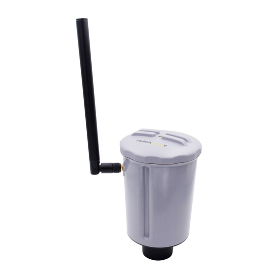
About product Terabee’s solution is a self-powered, low-energy and wireless IoT device - providing users with remote data on remaining material levels inside silos, tanks and vats. It integrates an optical (LED) ToF sensor for distance measurements with up to 60 meter range, also providing a non-intrusive way of monitoring material levels. -
Page 5: Lorawan Overview
LoRaWAN network. Please note that for successful data transmission, the user is responsible for Terabee device integration with a LoRaWAN network. This includes a LoRa gateway; registration of the Terabee device on a LoRa network server; and an application server of users choice. -
Page 6: Inside The Package
Inside the Package The following items & components are included in the standard LoRa Level Monitoring XL product offering: Components Visuals Comment LoRa Level Monitoring XL device LoRa Antenna Available in two versions : 1. 868 MHz 2. 915 MHz... -
Page 7: Onboard Features And Controls
Onboard features and controls External features Copyright © Terabee 2021 Terabee, 90 Rue Henri Fabre 01630, St Genis-Pouilly, France (next to CERN) 7/36... -
Page 8: Internal Features And Controls
Ensures water tight sealing between the level device and selected mounting equipment Important! Do not unscrew (untight) the vent plug on the level device, unless instructed by the Terabee team. Unscrewing the vent plug will compromise the IP65 seal. Internal features and controls Copyright ©... - Page 9 Available slot for hook insert (middle of lid). (includes plug) In cases when not used, please keep the provided insert plugged to avoid accumulation of water and dirt Copyright © Terabee 2021 Terabee, 90 Rue Henri Fabre 01630, St Genis-Pouilly, France (next to CERN) 9/36...
-
Page 10: Onboard Modes Overview
Onboard modes overview The Terabee device includes 4 modes, explained in more detail below: 1. Setup mode 2. Autotest mode 3. Sleep mode 4. Active mode Copyright © Terabee 2021 Terabee, 90 Rue Henri Fabre 01630, St Genis-Pouilly, France (next to CERN) -
Page 11: Setup Mode
Mode entered as soon as the device is connected to a PC via the USB 2.0 Micro-B interface. The mode is used mainly for device connection to the Terabee Configuration GUI, which allows users to perform distance measurement tests, network connection tests, and device parameter configuration/saving on device. -
Page 12: Sleep Mode (3), Active Mode (4
Sleep mode is the battery saving mode, allowing the device to achieve years of autonomy. The Terabee device will be in sleep mode for most of its time while deployed on the field. Based on pre-configured parameters, the Terabee device will wake up (exit) from the sleep mode and enter the active mode for a short period of time. -
Page 13: Led Notifications
Internal system error Device firmware has experienced a (0.1 sec intervals) detected crash Please see Appendix for recommended recovery steps on LED error notifications. Copyright © Terabee 2021 Terabee, 90 Rue Henri Fabre 01630, St Genis-Pouilly, France (next to CERN) 13/36... -
Page 14: Setup And Device Initiation
Setup and device initiation 1. Connect antenna Join the provided LoRa antenna with the Terabee device. To do this, locate the RP-SMA connector on the device external part, and gently screw in the antenna clockwise until it is locked. Please use the cap to screw the antenna to the device. Once the antenna is locked, hold the cap fixed (use one hand) and rotate the main antenna body to adjust for a preferred... -
Page 15: Activate Device
(Official product webpage → Downloads section → Documentation → LoRa Level Monitoring XL integration with The Things Network). Please note that without registering the Terabee device with a LoRa network, it is not possible to transmit data via LoRa protocol! 3. -
Page 16: Ready For Operations
Level Estimation : Disabled When using the Terabee Configuration GUI with the Terabee device, the software auto-fills the codes in the DevEUI and AppKey parameter fields. Device EUI (DevEUI) and Application Key (AppKey) codes for each device can be also found embedded in a QR code that is printed on a label - located on the inner side of the TOP lid. -
Page 17: Using Terabee Configuration Gui
LED will constantly blink GREEN, and it will continue to do so - as long as the Terabee device is linked to the PC. Power supply to the device is now provided via USB interface (battery is not affected). -
Page 18: Home Tab
Home tab Under the Control Panel, click on CONNECT DEVICE. The software will automatically recognize & display the USB port to which the Terabee device has been joined, and connect to the GUI. After successful connection - a dialog window will appear, showing currently configured device parameters. - Page 19 RECORDING. Select a preferred location for the file and click SAVE. When enough data is gathered, click on STOP RECORDING. Below is an example of distance measurements extracted on a Txt file from the Terabee Configuration GUI. At any point, the user can disconnect the device by clicking DISCONNECT DEVICE.
-
Page 20: Network Tab
Below is an example of fully configured unique device keys, using the OTAA activation method. The Terabee GUI allows automatic revert back to device default Device EUI, at any point - this can be done by clicking the circular arrow inside the Device EUI field. - Page 21 Radio Frequency (LoRa) Depending on the Terabee device version this field will indicate LoRa Radio Frequency : EU868 MHz or US915MHz. Please note that this parameter can not be modified using the Terabee Configuration GUI. Adaptive Data Rate (ADR) Enables the system to automatically set data rate and spreading factor for optimal performance.
- Page 22 SAVE TO DEVICE Once parameters have been configured, click on SAVE TO DEVICE (bottom left) to register and store configured network parameters to your Terabee device. A dialog window will appear to indicate successful parameter registration and also list these for confirmation.
-
Page 23: Application Tab
TEST NETWORK For OTAA operations, Terabee Configuration GUI offers users the possibility to test Terabee device connection to the network server and confirm whether the gateway is in range for successful data transmission via LoRaWAN. By clicking on TEST NETWORK (bottom right), the Terabee device will: 1. - Page 24 0 % fill level: distance (in cm) from bottom of the silo at which the device will register an empty silo (0% fill level) Device position: distance (in cm) from Terabee device to bottom point of the silo, at which the device will be installed. Position on Z axis.
-
Page 25: About Tab
field. The silo illustration (right side) provides a visual example of the 3 parameter setup. Important. Please note that the Terabee Configuration GUI is only used as a means to configure the device for operation. The software is not intended to provide any recommendations on most suitable mounting possibilities, or other information related to the device physical installation in the silo or tank. - Page 26 Please note that actual parameters under CONFIGURED DEVICE PARAMETERS section are ones selected in the Terabee Configuration GUI - and is not a list of settings currently saved on the device. Users also have the possibility to save modified parameters to the device (SAVE TO DEVICE) or download .json format file with configured parameters for further use outside the...
-
Page 27: Device Maintenance
● EU 868 MHz ● US 915 MHz In cases when the user prefers to integrate a non Terabee LoRa antenna, this is also possible. Please make sure that : (1) the selected antenna matches with available LoRa radio frequencies on the Terabee device, (2) antenna gain and power are supported by local regulations. -
Page 28: Battery Replacement
Battery replacement Battery compartment is located under the sealed top lid of the Terabee device. Before opening the device, ensure that water or moisture cannot enter the onboard electronics. Please follow these steps for battery replacement : Make sure the device is deactivated - onboard switch position is set to (0) -
Page 29: Battery Information & Handling Recommendations
Battery information & handling recommendations ● Batteries provided by Terabee are not rechargeable. Do not charge or open the battery. ● Do not expose the battery to ambient temperatures higher than 100 °C. Under no circumstances allow exposure to fire. -
Page 30: Device Cleaning
For an integrated self-cleaning system that will help avoid dust/dirt accumulation on sensor lenses, please contact the Terabee team to explore development opportunities. Copyright © Terabee 2021 Terabee, 90 Rue Henri Fabre... -
Page 31: Lorawan Communication
ToF sensor (50cm) Target too far 65535 0xFFFF Detected target is farther than the maximum range of the ToF sensor (60m) Copyright © Terabee 2021 Terabee, 90 Rue Henri Fabre 01630, St Genis-Pouilly, France (next to CERN) 31/36... - Page 32 Device position (Z axis) - distance from bottom of silo to the exact point where the Terabee device will be installed (reference point is the sensor lenses). By default, material fill level estimation is disabled. If enabled, this value is then computed onboard the device after every ToF measurement - by converting the raw distance data collected (sensor-to-material surface) into remaining material fill level (%).
- Page 33 System failed to read voltage from the battery. If possible, please restart the device. TOF_TIMEOUT System failed to get a response from the onboard ToF distance sensor. If possible, please restart the device. Copyright © Terabee 2021 Terabee, 90 Rue Henri Fabre 01630, St Genis-Pouilly, France (next to CERN) 33/36...
-
Page 34: Uplink Payload Decoding Function (Example)
"LEVEL_ERROR"; return level; function decodeDistance(distance){ (distance === 0) return "TARGET_TOO_CLOSE"; (distance === 65535) return "TARGET_TOO_FAR"; (distance === 1) return "INVALID_READING"; return distance; Copyright © Terabee 2021 Terabee, 90 Rue Henri Fabre 01630, St Genis-Pouilly, France (next to CERN) 34/36... - Page 35 | bytes[1]); levelPercentage = decodeLevelPercentage(bytes[2]); batteryVoltage = bytes[3]<<8 | bytes[4]; errorCode = decodeErrors(bytes[5]); return distance: distance, levelPercentage: levelPercentage, batteryVoltage: batteryVoltage, errorCode: errorCode Copyright © Terabee 2021 Terabee, 90 Rue Henri Fabre 01630, St Genis-Pouilly, France (next to CERN) 35/36...
-
Page 36: Appendix
(DevEUI, AppEUI, AppKEY, devAddr, appSKey, nwkSKey), selecting appropriate spreading factor or data transmission intervals. This can be done using the Terabee Configuration GUI. If the error persists, please contact Terabee support Network connection Device is programmed to restart 1.
Need help?
Do you have a question about the LoRa Level Monitoring XL and is the answer not in the manual?
Questions and answers