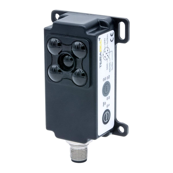
TeraBee IND-TOF-1 Manual
Connection to personal computer
Hide thumbs
Also See for IND-TOF-1:
- Manual (9 pages) ,
- Quick setup manual (2 pages) ,
- User manual (48 pages)

Related Manuals for TeraBee IND-TOF-1


Summary of Contents for TeraBee IND-TOF-1
- Page 1 Terabee IND-TOF-1 Connection to Personal Computer (Guide) Technical support: terabee.com/support/ Sales and commercial support: terabee-sales@terabee.com...
- Page 2 1. Introduction The purpose of this document is to give guidelines for connection and use of the Terabee IND-TOF-1 distance sensor with a Personal Computer (PC). 2. PC setup instructions The following section provides guidelines on connection and sensor evaluation on a PC, ®...
- Page 3 ● Power Supply capable of supplying 24 V DC @ 100mA Figure 2. Sensor and PC hardware setup diagram The following summarizes the steps to be taken for connecting the IND-TOF-1 sensor to a Please note that there is some soldering involved, as the M12 connector is not directly compatible with the D-Sub 09 PoS connector of the RS485-to-USB adapter.
- Page 4 Table 2 - Wiring connection between IND-TOF-1 and D-Sub 09 PoS connector M12 cable D-Sub 09 PoS connector Tx/Rx+ (pin 4) Pin 2 Tx/Rx- (pin 5) Pin 1 Ground (pin 2) Pin 5 Step 3 Connect the power lines of the M12 cable to a power supply source. See wiring instructions Table 3.
- Page 5 2.2. Software setup As the Terabee IND-TOF-1 sensor uses the MODBUS RTU protocol for data communication via RS485 interface, for operation on PC we recommend to work with MODBUS Doctor freeware utility software (KScada). To do so, please follow the link below to the official page of KScada and download the MODBUS Doctor software.
- Page 6 Figure 4. Status after pressing “Connection” 2.3. Basic sensor parameter configuration To learn more about IND-TOF-1 operating modes and their setup and functionality, please refer to the official product user manual. To learn more about all configurable sensor parameters, please refer to the official...
- Page 7 Figure 5. Read distance data command execution example 2.3.2. Switching between operating modes Terabee IND-TOF-1 provides users with 6 operating modes (learn more about each mode functionality in the official user manual). By default the sensor is shipped with operating mode 1 pre-set.
- Page 8 Click “READING” to execute the command. The LED indicators (Tx; Sel) will blink RED and BLUE. Operating mode number is now displayed in the “Value” field. Copyright © Terabee 2023 Terabee, 90 rue Henri Fabre Terabee IND-TOF-1 01630 Saint-Genis-Pouilly, France (next to CERN)
Need help?
Do you have a question about the IND-TOF-1 and is the answer not in the manual?
Questions and answers