
Related Manuals for GEM 1436 cPos


Summary of Contents for GEM 1436 cPos
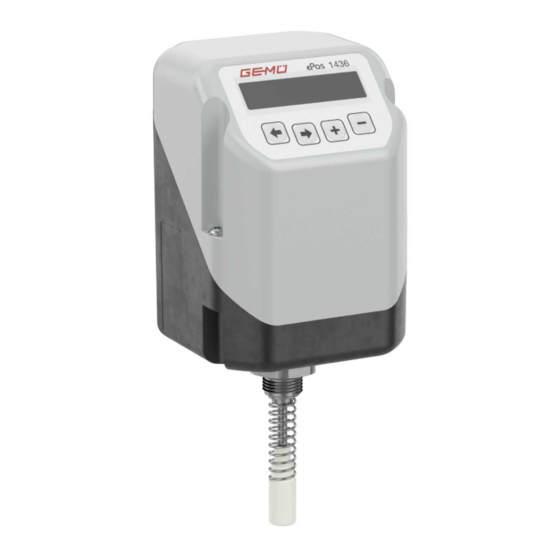
- Page 1 GEMÜ 1436 cPos Intelligent positioner and integrated process controller Operating instructions further information webcode: GW-1436...
- Page 2 All rights including copyrights or industrial property rights are expressly reserved. Keep the document for future reference. © GEMÜ Gebr. Müller Apparatebau GmbH & Co. KG 31.10.2023 GEMÜ 1436 cPos 2 / 76 www.gemu-group.com...
-
Page 3: Quick Commissioning
(for example LEAKAGE). ▶ Manual initialization with sequential movement through the menu by the operator or, if possible, acknowledging the error message to repeat the step may help here (see “Manual initialization“, page 32). www.gemu-group.com 3 / 76 GEMÜ 1436 cPos... - Page 4 If the message Init Valve Ok appears, the product is ready for operation and can be set to the desired operating mode. Further information (see “Working level (Mode)“, page 39). If an error message appears during the initialization process (see “Error messages during initialization“, page 35). GEMÜ 1436 cPos 4 / 76 www.gemu-group.com...
-
Page 5: Table Of Contents
Fail safe function ........... without a valve) ..........Product label ..........15.3 Setting the throttle screws ......15.3.1 Travel time measurement during 5 GEMÜ CONEXO ............ initialization ........6 Intended use ............16 Operation ............. 7 Order data ............17 Troubleshooting .......... -
Page 6: General Information
The following symbols for the specific dangers can be used within a warning note: Working medium Symbol Meaning The medium that flows through the GEMÜ product. Danger of explosion Control function The possible actuation functions of the GEMÜ product. Control medium... -
Page 7: Safety Information
7. Observe the safety data sheets. 4.2 Description 8. Observe the safety regulations for the media used. The GEMÜ 1436 cPos digital electro-pneumatic positioner has During operation: an optional integrated process controller to control pneumat- 9. Keep this document available at the place of use. -
Page 8: Function
A change to the device version can also be due to technical changes to the hardware, which is why several device versions describe the same firmware version. Device Firmware version Effective Changes version from V2.0.0.0 05/2014 GEMÜ 1436 cPos 8 / 76 www.gemu-group.com... -
Page 9: Intended Use
The valve position and the integrated travel sensor can be monitored via the electrical connections. The pneumatic actuator is directly operated and controlled by means of the pilot valves. ● Use the product in accordance with the technical data. www.gemu-group.com 9 / 76 GEMÜ 1436 cPos... -
Page 10: Order Data
4 Action Single acting 5 Device version SA01 Positioner 6 Option Without 7 Flow rate 150 l/min 8 Travel sensor length Potentiometer, 30 mm length 9 Type of design Standard 10 CONEXO Without GEMÜ 1436 cPos 10 / 76 www.gemu-group.com... -
Page 11: Technical Data
2) Reference condition: 6 → 5 bar at 25 °C Air consumption: 0 Nl/min (when idle) 8.5 Mechanical data Installation position: Optional Protection class: IP 65 acc. to EN 60529 Weight: 600 g www.gemu-group.com 11 / 76 GEMÜ 1436 cPos... - Page 12 - Set value and actual value input are not galvanically isolated from each other Set value input: 0/4 - 20 mA (adjustable) Process actual value in- 0/4 - 20 mA (adjustable) put: Only for device version code PA01 GEMÜ 1436 cPos 12 / 76 www.gemu-group.com...
- Page 13 < 8 V DC 8.7.5 Digital output Switching outputs: K1 / K2 Function: Can be selected using software Switching voltage: Supply voltage max. 0.5 A Drop voltage: Max. 2.5 V DC at 0.5 A www.gemu-group.com 13 / 76 GEMÜ 1436 cPos...
- Page 14 Default setting / The control characteristic is adjustable. Set value input (mA) During initialization, the 1436 cPos positioner automatically detects the control function of the valve and adjusts itself by default so that the valve is closed when the signal is 0/4 mA.* The assignment can subsequently be changed using parameters.
- Page 15 *** Two switches are connected in series internally between connection X1 and X3. Communication lead time during operation in line structure (connection X1 and X3) therefore double that of a "standard two- port device". www.gemu-group.com 15 / 76 GEMÜ 1436 cPos...
-
Page 16: Dimensions
9 Dimensions 9 Dimensions 9.1 Positioner dimensions □ □ M 16x1 SW 27 41,5 26,5 □ Travel sensor length Code 10.3 32.5 57.5 Dimensions in mm GEMÜ 1436 cPos 16 / 76 www.gemu-group.com... -
Page 17: Direct Mounting To Quarter Turn Actuators
For dimensions of travel sensors 4231 and 4232, which are used to measure the travel from the process valve, as well as the mounting bracket for wall mounting and the external mounting option with the corresponding mounting bracket for quarter turn actuators of the 1436, see the 1436 cPos datasheet. www.gemu-group.com 17 / 76 GEMÜ... -
Page 18: Manufacturer's Information
3. Do not exceed the maximum storage temperature (see chapter "Technical data"). 4. Do not store solvents, chemicals, acids, fuels or similar fluids in the same room as GEMÜ products and their spare parts. 11 Assembly 11.1 Preparations for assembly to the valve 1. -
Page 19: Preparations For Assembly To The Valve (Quarter Turn Actuator)
(the electrical operating range is located in the travel range between the 0° and 90° positions). 3. Place the adapter 4 onto the shaft of the rotary travel sensor 2 without twisting the shaft. www.gemu-group.com 19 / 76 GEMÜ 1436 cPos... -
Page 20: Direct Mounting On Linear Actuators
5. Mount the external rotary travel sensor 7 with the adapter 4 on the mounting bracket 6. 6. Note the direction of the scale 8. ð View from below of the travel sensor 7 with mounting bracket 6. GEMÜ 1436 cPos 20 / 76 www.gemu-group.com... -
Page 21: Remote Mounting On Linear Actuators
4. Secure the product 1 in a suitable position. NOTICE Mounting bracket ▶ The GEMÜ 1436 000 ZMP mounting bracket, which is available separately, can be used for this. 5. The 5-pin M12 travel sensor connector must be connected to the 5-pin M12 socket on the base of the product. -
Page 22: Remote Mounting To Quarter Turn Actuators
1. Fix the positioner 1 somewhere suitable. NOTICE Mounting bracket ▶ The GEMÜ 1436 000 ZMP mounting bracket, which is available separately, can be used for this. 2. Mount (see “Rotary travel sensor mounting kit assembly“, page 19)the travel sensor mounting kit. -
Page 23: Checking The Mechanical Mounting
In the case of linear tion 1 and 2) travel sensors, check the mounting parts used for compat- Working connec- G1/8 ibility. tion for process valve (control func- tion 3) * only double acting type (code 3) www.gemu-group.com 23 / 76 GEMÜ 1436 cPos... -
Page 24: Connection Diagram For Linear Actuators
12.1.1 Connection diagram for NC valves (Normally Closed) ● Fit tubing from 2 to connector 2 of the quarter turn actu- ator. ● Fit tubing from 2 to the lower connection of the process valve. GEMÜ 1436 cPos 24 / 76 www.gemu-group.com... -
Page 25: Connection Diagram For Double Acting Valves
1) Switching output switches device supply voltage U - drop voltage 13 Electrical connection NOTICE Risk of cable break ▶ Overtightening can result in damage to the internal cables. Turn electrical connections once by max. 360°. ● www.gemu-group.com 25 / 76 GEMÜ 1436 cPos... - Page 26 13.5 Actual value input (sensor signal for process controller) Plug Signal name Wiring X+, process internal external 0 - 20 mA / 4 - 20 mA actual value input X -, process actual value input GEMÜ 1436 cPos 26 / 76 www.gemu-group.com...
- Page 27 Set value in- Actual value mode put as digital input as di- input "in W" gital input "in X" Positioner AUTO Positioner MANUAL Process con- AUTO troller Process con- MANUAL troller High 11mA www.gemu-group.com 27 / 76 GEMÜ 1436 cPos...
- Page 28 Low level (0...8 V DC) Use of actual value input as digital input "In X" Plug Signal name Wiring I-, actual value input internal external High level (14...28 V DC) Low level (0...8 V DC) GEMÜ 1436 cPos 28 / 76 www.gemu-group.com...
-
Page 29: Fail Safe Function
CAUTION Set value < 4.0 Single acting: Single acting: - Cleaning agent adjustable ▶ Damage to the GEMÜ product. function (range below I The plant operator is responsible for selecting the clean- ● Min W can be ing material and performing the procedure. -
Page 30: Without Default Setting (When Supplied Without A Valve)
NOTICE ▶ Experience has shown that valve travel times of approx. 1–2 seconds produce optimal positioner results. It may not be possible to reach this operating time range for large-volume actuators. GEMÜ 1436 cPos 30 / 76 www.gemu-group.com... - Page 31 If the message Init Valve Ok appears, the product is ready for operation and can be set to the desired operating mode. Further information (see “Working level (Mode)“, page 39). If an error message appears during the initialization process (see “Error messages during initialization“, page 35). www.gemu-group.com 31 / 76 GEMÜ 1436 cPos...
- Page 32 In order to prevent incorrect operation, the parameters from manual initialization are only accepted when they comply with the requirements for correct function. - For manual initialization proceed as described on the next page. GEMÜ 1436 cPos 32 / 76 www.gemu-group.com...
- Page 33 15 Commissioning 15.2.3 Menu structure – automatic and manual initialization www.gemu-group.com 33 / 76 GEMÜ 1436 cPos...
- Page 34 The quantity of calibration points when initializing can be changed. Example: QtyCalPoint=9 means: The valve will be examined for control features between the end position stops in 9 posi- tions (10% steps here). GEMÜ 1436 cPos 34 / 76 www.gemu-group.com...
- Page 35 In W In X no Signal No signal at digital input In X Parameter In X is set to OFF / ON or Connect signal to digital input Safe / ON In X www.gemu-group.com 35 / 76 GEMÜ 1436 cPos...
- Page 36 Control function 2 Control function 2 (opened by spring force) (opened by spring force) (Opened by spring force) DA²⁾ Control function 3 Control function 3 Control function 3 (double acting) (double acting) (Double acting) GEMÜ 1436 cPos 36 / 76 www.gemu-group.com...
- Page 37 If, in these versions, a control function is set for simple pilot valves, this leads to a reduction in the flow capability. ⁴⁾A manual initialization should only ever be carried out if you have not achieved satisfactory control characteristics with the automatic initialization or this was aborted due to an error message. www.gemu-group.com 37 / 76 GEMÜ 1436 cPos...
-
Page 38: Setting The Throttle Screws
Otherwise this could result in negative control res- ults and incorrect error messages. GEMÜ 1436 cPos 38 / 76 www.gemu-group.com... -
Page 39: Operation
Select operating AUTO AUTO mode MAN-FLEX TEST The Mode menu item can be used to select between the oper- ating modes A (Auto), M (Manual), F (Manual-Flex), T (Test) and OFF (pause mode). www.gemu-group.com 39 / 76 GEMÜ 1436 cPos... - Page 40 Communication The Communication menu is used to set the various op- tions for communication with the product. GEMÜ 1436 cPos 40 / 76 www.gemu-group.com...
- Page 41 16.2.3.2.1.2 Switching the process controller on or off (optional) r0w0 SETUP Mode w XX.X: x XX.X AUTO automatic operation Automatikbetrieb r0w3 w XX.X: x XX.X Mode manual operation manueller Betrieb Mode Service SetBasics SetFunction r0w3 ProcCtrlMode: ON...OFF www.gemu-group.com 41 / 76 GEMÜ 1436 cPos...
- Page 42 The access priorities needed are marked in the configuration menu. The way in which access codes can be changed is described under "Activation or deactivation of user access". (see “Activating/ deactivating user access“, page 51) GEMÜ 1436 cPos 42 / 76 www.gemu-group.com...
- Page 43 Submenu for setting access authorisations Code Password entry 0 ... 10000 Logout Block access New Code: 1 Release the lowest prior- 0 ... 10000 New Code: 2 Release the medium pri- 0 ... 10000 ority www.gemu-group.com 43 / 76 GEMÜ 1436 cPos...
- Page 44 Time for an automatic re- 1 ... 60 min 5 min turn to the working level - Setup HelpLanguage Text language D / GB / N HelpText Display the help text ON / OFF 3 SetFunction GEMÜ 1436 cPos 44 / 76 www.gemu-group.com...
- Page 45 "In X" Safe / ON ParmSetB0 ParmSetB1 Poti / Ix In 1 Determines the function OFF / ON of the digital input "In 1" Safe / ON ParmSetB0 ParmSetB1 Poti / Ix www.gemu-group.com 45 / 76 GEMÜ 1436 cPos...
- Page 46 K2 Fn Determines the function of output K2 P min P max P min/max W min W max W min/max X min X max X min/max SSE min SSE max SSE min/max GEMÜ 1436 cPos 46 / 76 www.gemu-group.com...
- Page 47 W 100 % 0 ... 100 % 100.0 % Y-Direction* Determines the direction rise / fall rise of the process controller output (rising/falling) OutMinPos Valve position at actual 0 ... 100 % 0.0 % value output signal 0/4 mA www.gemu-group.com 47 / 76 GEMÜ 1436 cPos...
- Page 48 Serial Bdrate RS Defines the baud rate of 38400 115200 the RS 232 connection 57600 115200 *Only for activated process controllers **Parameter value is automatically calculated and set by the positioner during initialization GEMÜ 1436 cPos 48 / 76 www.gemu-group.com...
- Page 49 16 Operation 16.2.3.5 Menu 1 Service www.gemu-group.com 49 / 76 GEMÜ 1436 cPos...
- Page 50 ▶ If the deviation is too large, this is shown by a dot on the left-hand side or right-hand side of the display. In this case, the po- sitioner can no longer work. All parameters on the control system route must be checked. In w:x:1:2 Displays the current conditions of the digital inputs ( = Signal High). Relay: GEMÜ 1436 cPos 50 / 76 www.gemu-group.com...
- Page 51 2 required for writing r3: top priority release code 3 required for reading w3: top priority release code 3 required for writing The codes can be changed or activated in the following menu: www.gemu-group.com 51 / 76 GEMÜ 1436 cPos...
- Page 52 16.2.3.5.1.3 Reading out, deleting and deactivating error messages SETUP Service SetBasics SetFunction SetCalibration Communication Return Diagnosis Login I / O Status Error List: GEMÜ 1436 cPos 52 / 76 www.gemu-group.com...
- Page 53 Displays the current software release. S/N: Displays the positioner serial number TAG1: An 11-digit TAG number can be entered for identification of the positioner. TAG2: An 11-digit TAG number can be entered for identification of the positioner. www.gemu-group.com 53 / 76 GEMÜ 1436 cPos...
- Page 54 GB-English and N-Norwegian. HelpText: The help texts that appear as a default in the second line of the display can be masked. If the help texts are masked, the key assignment is displayed. GEMÜ 1436 cPos 54 / 76 www.gemu-group.com...
- Page 55 16 Operation 16.2.3.7 Menu 3 SetFunction www.gemu-group.com 55 / 76 GEMÜ 1436 cPos...
- Page 56 1:50) or >4.0 (if the characteristic IxTime curve is 1:25) in order to close the valve fully. IxTime Signal input filtered Signal input filtered 16.2.3.7.1.3 Setting the dead zone DeadBand: GEMÜ 1436 cPos 56 / 76 www.gemu-group.com...
- Page 57 AlarmMaxK1 ParmSetB1 Loads para- (W min/max) Above or below the preset set meter sets value into the work- ing memory (X min) Lower than the actual value preset under AlarmMinK1 www.gemu-group.com 57 / 76 GEMÜ 1436 cPos...
- Page 58 AlarmMaxK2 Memory 2 (SSE min/max) Above or below the preset ac- Memory 3 tual value Memory 4 Active Active if the controller is in Default setting the OFF-mode Error Error message GEMÜ 1436 cPos 58 / 76 www.gemu-group.com...
- Page 59 Poti: The actual valve position is emitted at the 4-20 mA output. The current actual value is displayed at the 4–20 mA output (only available in the version with integrated process control- ler) www.gemu-group.com 59 / 76 GEMÜ 1436 cPos...
- Page 60 16 Operation 16.2.3.8 Menu 4 SetCalibration GEMÜ 1436 cPos 60 / 76 www.gemu-group.com...
- Page 61 Stroke x W-Direction[rise] Valve W-Direction[fall] OPEN Valve Set value w [%] CLOSED Working as a process controller: Input signal W-Direction[rise] in mA W-Direction[fall] X-Direction[rise] X-Direction[fall] Set value w [%] Actual value x [%] www.gemu-group.com 61 / 76 GEMÜ 1436 cPos...
- Page 62 - xx °C / °F → temperature control - Linear actuators: Valve spindle falls when valve opens - xx bar / psi → pressure control - xx l/h / m³/h → flow control GEMÜ 1436 cPos 62 / 76 www.gemu-group.com...
- Page 63 Display when Scaling ON (e.g. mbar) is set: r3w3 SETUP A: W XX.X mbar Mode AUTO XX.X mbar automatic operation Automatikbetrieb r3w3 Mode XX.X mbar XX.X mbar manual operation manueller Betrieb Mode Service Configuration menu Konfigurationsmenü www.gemu-group.com 63 / 76 GEMÜ 1436 cPos...
-
Page 64: Troubleshooting
For details see separate operating instructions. 16.2.3.9.1.2 13.5.2. Setting the communication parameters NOTICE ▶ For details on how to use the GEMÜ e.sy-com interface and operating the browser see separate operating instructions. WebServer: Submenu for setting the communication parameters RS 232:... - Page 65 Error ROM. card EEPROM could not be switched on and then disappears read. automatically. The automatic control system still operates cor- rectly, but the controller must be sent to GEMÜ for examination. www.gemu-group.com 65 / 76 GEMÜ 1436 cPos...
- Page 66 EEPROM could not be read from Information while attempting to access or written to. Send the controller an EEPROM. to GEMÜ for repair. Error message Description Condition for the occurrence Error cause of the error...
-
Page 67: Inspection And Maintenance
Proportional action factor Kp (see Glossary) No spare parts are available for this product. If it is faulty, Derivative action time Tv (see Glossary) please return it to GEMÜ for repair. Differential component (D component) (see Glossary) Integral-action component (I component) Ki (see Glossary) 18.2 Cleaning the product... - Page 68 - If necessary, re-adjust the Kp and Tn values a little until the Proc T: control system shows satisfactory behaviour Larger: The system deviation has a 20.5 Differential equation of the product longer effect although set value = actual value GEMÜ 1436 cPos 68 / 76 www.gemu-group.com...
- Page 69 20 General information regarding control engineering 20.7 Control characteristics and transitory responses Transit function Transitory response Control response D component I component P component ≈T www.gemu-group.com 69 / 76 GEMÜ 1436 cPos...
-
Page 70: Disposal
If continuously until the actual value reaches the set value. The no return delivery note is included with the product, GEMÜ regulation ratio will be integrated upwards or downwards as cannot process credits or repair work but will dispose of the long as a system deviation exists. -
Page 71: Eu Declaration Of Conformity In Accordance With 2014/30/Eu (Emc Directive)
2014/30/EU (EMC Directive) EMC introductory text We, the company GEMÜ Gebr. Müller Apparatebau GmbH & Co. KG Fritz-Müller-Strasse 6–8 74653 Ingelfingen-Criesbach, Germany hereby declare under our sole responsibility that the below-mentioned product complies with the regulations of the above-men- tioned Directive. -
Page 72: Eu Declaration Of Conformity In Accordance With 2011/65/Eu (Rohs Directive)
In accordance with 2011/65/EU (RoHS Directive) EMC introductory text We, the company GEMÜ Gebr. Müller Apparatebau GmbH & Co. KG Fritz-Müller-Strasse 6–8 74653 Ingelfingen-Criesbach, Germany hereby declare under our sole responsibility that the below-mentioned product complies with the regulations of the above-men- tioned Directive. -
Page 73: Declaration Of Incorporation According To 2006/42/Ec (Machinery Directive)
EC Machinery Directive 2006/42/EC, Annex II B Machinery Directive introductory text We, the company GEMÜ Gebr. Müller Apparatebau GmbH & Co. KG Fritz-Müller-Strasse 6–8 74653 Ingelfingen-Criesbach, Germany hereby declare under our sole responsibility that the below-mentioned product complies with the relevant essential health and safety requirements in accordance with Annex I of the above-mentioned Directive. -
Page 74: Keyword Index
FindFnct.................. 34 OutMaxPos................ 62 OutMinPos................ 62 Go Close ................... 34 Go Open .................. 34 Pos Ctrl In ................. 50 Pos Ctrl Out ................ 50 Pos D.................. 56 HelpLanguage ................ 54 Pos P.................. 56 HelpText ................... 54 Pos T.................. 56 Hold................... 58 Pot Abs .................. 50 hrs ..................... 53 GEMÜ 1436 cPos 74 / 76 www.gemu-group.com... - Page 75 T (Test) .................. 39 TAG1 .................. 53 TAG2 .................. 53 V: X.X.X.X.................. 53 Valve .................. 50 W Pos X .................. 50 W Proc X ................... 50 Warnings................... 53 W-Direction ................ 61 WebServer ................ 64 W-Function ................ 62 W-Input .................. 54 X-Direction ................ 61 X-Input .................. 54 Y-Direction ................ 62 www.gemu-group.com 75 / 76 GEMÜ 1436 cPos...
- Page 76 GEMÜ Gebr. Müller Apparatebau GmbH & Co. KG Fritz-Müller-Straße 6-8, 74653 Ingelfingen-Criesbach, Germany Subject to alteration Phone +49 (0) 7940 1230 · info@gemue.de www.gemu-group.com 10.2023 | 88243865...
Need help?
Do you have a question about the 1436 cPos and is the answer not in the manual?
Questions and answers