Advertisement
Quick Links
Control Unit for LED Light Units
PB-2430-1 Instruction Guide
Thank you for purchasing a CCS product. To ensure proper use of the product, please
read this instruction guide before use and keep it for your future reference.
1
Introduction
PB-2430-1 is an analog control unit for controlling LED lights. It controls LED lights principally used
for machine vision and industrial inspections.
Features
Operates on 24 VDC.
Up to 24 W of 24 V LED lights can be connected.
LED lights can be connected using SM connectors.
Lights are adjusted using variable voltage control.
The radiant quantity can be adjusted with light control knob on the front panel.
2
Important Information for Equipment Safety
This product has been designed with full consideration of safety. However, incorrect usage of the
product may result in fire, electric shock, or other serious damages. Please ensure to follow the
conditions below.
Symbol Descriptions
Warning
Indicates that incorrect usage may result in serious injury or death.
Caution
Indicates that incorrect usage may result in injury or property damage.
Symbol Examples
symbols indicate caution (also including danger and warning).
The example shown here indicates a fire caution.
FIRE HAZARD
symbols indicate prohibited acts.
The example shown here indicates prohibition to disassemble.
DISASSEMBLY
PROHIBITED
D o not disas semble or mo dif y t he
product. Doing so may result in fire or
electric shock.
DISASSEMBLY
PROHIBITED
Please unplug the power cord when
c o n n e c t i n g o r d i s c o n n e c t i n g t h e
product and peripherals. Otherwise it
FIRE HAZARD
may cause fire and/or electric shock.
D o n o t t o u c h t h e p o w e r c o r d s o r
c onnec t per ipheral devic es dur ing
lightning. This may result in electric
shock.
SHOCK HAZARD
If abnormal condition occurs such as fuming, heat, smell, noise, or so on, stop using the product
immediately, and turn the power off. A fire or electric shock may result if the product is kept used.
D o n o t p l a c e t h e p r o d u c t u n d e r
direct sunlight or in a high humidity
environment. Doing so may result in
FIRE HAZARD
fire due to internal temperature rise.
Always place the product on a stable
and flat location. Not doing so may
result in the product falling or toppling,
PROHIBITED
which may cause bodily injury.
Do not use user-made branch cables.
Doing so may cause product failure.
PROHIBITED
D o n ot di s c o n n e c t p owe r c o r d o r
disassemble product while operating.
Doing so may cause the product to
PROHIBITED
malfunction.
Do not drop or subject the product
to impact. Doing so may cause the
product to malfunction.
PROHIBITED
To avoid product surface discoloration
or deterioration, do not wipe product
with volatiles such as paint thinner or
PROHIBITED
benzene.
Ve r i f y p o l a r i t y o f t e r m i n a l s b e f o r e
connecting cables. If polarity is reversed, it
may cause fires or damage the equipment.
PROHIBITED
When mount the unit in a system rack
o r c a s e, t h e p o r t i o n o f t h e s c r e w s
penetrating the case must be less than
MANDATORY
3 mm long.
ACTIONS
- Read Before Use -
-1-
Warning
Do not touch the product with wet hands.
Doing so may result in electric shock.
Make sure that the product is free of moisture
or any liquid. Exposure to water may result in
fire or electric shock.
This product generates high temperatures.
Do not touch the product while it is turned on or
immediately after it is turned off, or burning may
result. Provide cooling with a fan or other ventilation
if the product is to be used in a closed space.
Caution
Please use designated power sources with
stable voltage. Sharing a power source with
inverters, motors, etc. may cause malfunction.
Make sure that connected lighting is within the
power rating of this product. Not doing so may
cause product failure.
Do not bundle product cables with high-voltage
lines or power lines. Doing so may cause
the product to malfunction. Keep the product
cables as far away from such lines as possible.
Before moving the product, disconnect cables.
Damaging the cables may result in f ire or
electric shock.
Do not bend or jam cables when wiring the
product. Doing so may cause product failure.
Make sure to hold and pull from the plugs when
disconnecting the cables. Not pulling from the
plugs may damage the cable and result in fire
or electric shock.
Use a dry cloth to remove dust or other foreign
matter from the plug electrodes. Failure to do
so may result in fire.
Make sure that the length of the extension
cable is less than 5 m. If the extension cable is
longer than 5 m, the light intensity will decrease
due to the DC resistance of the cable.
-2-
3
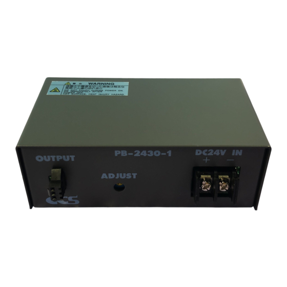
Name of each part
Front view
Output connector for 24 V light
PB-2430-1
OUTPUT
ADJUST
Intensity control knob
4
Connecting
Installation location
Please install products to locations with following conditions. Incorrect installation
Caution
location may cause product failure.
In a flat and stable location with minimal vibration.
Well-ventilated places with minimal dust.
Places that are not subject to sudden temperature
changes.
Installation Direction
Install the product in the following direction.
PB-2430-1
OUTPUT
ADJUST
Installation screw hole
(Insert depth of 3 mm max.)
(Tightening torque: 0.3 N•M max.)
Installation screw (M3)
Mounting the Unit to DIN Rail
Mounting to DIN Rail
Hook the tab on the upper part of the product on the DIN rail
and press the product in the direction indicated by arrow 2
while pressing it in the direction indicated by arrow 1.
Connecting
Before connection, make sure that the power is turned OFF. Making connections with the
Caution
power ON may result in a fire or electric shock.
DO NOT TOUCH
Do not bundle product cables with high-voltage lines or power lines. Doing so may cause the
WITH SET HANDS
Caution
product to malfunction. Keep the product cables as far away from such lines as possible.
1
C onnect the LED lights to the output
DO NOT SUBJECT
TO MOISTURE
connectors on the product.
2
Connect the power cables for 24 VDC.
MANDATORY
Connect the power cables for 24 VDC from the
ACTIONS
supply to the input terminals on the product.
MANDATORY
Caution
ACTIONS
Do not connect the power cable with the positive
and negative terminals reversed.
* Power cable
Be sure to connect cables properly with insulated M3 crimp
terminals (width: 6.2 mm max.).
SHOCK HAZARD
Improper connections may cause fires or product failure.
5
Operating Instructions
MANDATORY
ACTIONS
1
Turn on the power.
Lights connected to the product will turn on when power is supplied.
MANDATORY
ACTIONS
* There is no power switch on the product.
2
Preparation to capture images
MANDATORY
Focus the imaging device, such as a camera, onto the inspection object.
ACTIONS
Adjust light range, light angle, and radiant quantity to optimize images.
3
Light control
MANDATORY
ACTIONS
Turn the light control knob clockwise to make the
light brighter, and turn it counterclockwise to make
the light dimmer.
MANDATORY
ACTIONS
* The light adjustment range is 15.0 to 23.0 VDC.
* If the input DC voltage is less than the rating voltage, the output
voltage will be approximately 1.0 V lower than the input DC
MANDATORY
voltage even at the maximum intensity.
ACTIONS
MANDATORY
ACTIONS
Output connector configuration
DC24V IN
+
-
Pin number
1
2
3
Input terminal
block (24 VDC)
Connector
Places free from any water, oil, liquid, chemical, or steam.
Places free from corrosive or combustible gas.
Places away from water faucets, boilers, humidifiers, air
conditioners, heaters, or stoves.
Vertical Mounting
DC24V IN
+
-
Caution
Stationary plate
In case of attaching the product
vertically, the Output connector
side should be up and the Input
terminal block side should be
down for the heat radiation.
Removing from DIN Rail
1
2
Press the Unit down in the direction indicated by
arrow 3 and pull it out in the direction indicated
by arrow 4.
-3-
Output connector
OU TP UT
Light cable
Slotted screwdriver or
philips screwdriver
-4-
OUTPUT
3
2
1
Output connector
OUTPUT +24 V
NC
OUTPUT-
SMP-03V-BC
Mount with
this side up.
3
4
Power cable *
PB -24 30 -1
DC 24 V IN
AD JU ST
GND
+24 VDC
Philips
screwdriver
OU TP UT
PB -24 30 -1
DC 24 V IN
AD JU ST
Intensity control knob
Advertisement

Subscribe to Our Youtube Channel
Related Manuals for CCS PB-2430-1


Summary of Contents for CCS PB-2430-1
- Page 1 (24 VDC) Connector SMP-03V-BC Introduction Connecting PB-2430-1 is an analog control unit for controlling LED lights. It controls LED lights principally used Installation location for machine vision and industrial inspections. Please install products to locations with following conditions. Incorrect installation Caution location may cause product failure.
- Page 2 Contents of this Instruction Guide may be changed without prior notice. Illustrations used in this Instruction Guide may differ from actual products. CCS maintains the copyright on this Instruction Guide. Unauthorized transfer or reproduction is strictly prohibited. http://www.ccs-grp.com/ Copyright© 2018 CCS Inc. All Rights Reserved.
Need help?
Do you have a question about the PB-2430-1 and is the answer not in the manual?
Questions and answers