Table of Contents
Advertisement
Quick Links
ANSI/ASSP Z359.14-2021 (Class 1)
; For identification of product codes, refer to Table 1. See "Table 1 - Product Specifications" for more product information.
1
2
B
Connectors
Model
A
3100517
1
3100518
1
3100519
1
C4
3100520
1
C1
3100521
1
C1
3100522
1
C1
3100523
1
C3
3100524
1
C3
3100525
1
C3
3100526
1
C3
3100527
1
C3
3100528
1
C4
3100529
1
C4
3100530
1
C6
3100531
1
C6
3100532
1
3100533
1
3100534
1
3100535
1
C3
OSHA 29 CFR 1910.140
OSHA 29 CFR 1926.502
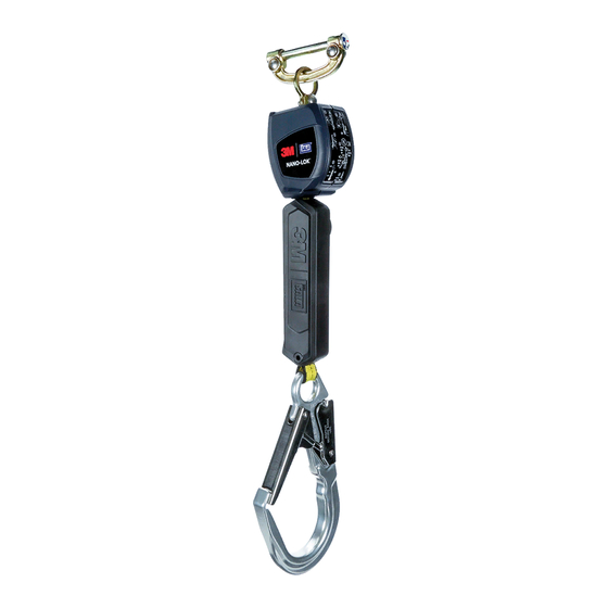
figure 1 - Product Overview
A
B
Housing
Lifeline
Size
B
C16
Size A
C9
Size A
C16
Size A
C7
Size A
C15
Size A
C5
Size A
C9
Size A
C16
Size A
C14
Size A
C7
Size A
C5
Size A
C9
Size A
C14
Size A
C15
Size A
C7
Size A
C5
Size A
C15
Size A
C7
Size A
C15
Size A
3M™ NANO-LOK
SELf-RETRACTINg DEvICES
USER INSTRUCTIONS
WL
X
Extended Length
(X)
DP1
6 ft. (1.8 m)
DP1
6 ft. (1.8 m)
DP1
6 ft. (1.8 m)
DP1
6 ft. (1.8 m)
DP1
6 ft. (1.8 m)
DP1
6 ft. (1.8 m)
DP1
6 ft. (1.8 m)
DP1
6 ft. (1.8 m)
DP1
6 ft. (1.8 m)
DP1
6 ft. (1.8 m)
DP1
6 ft. (1.8 m)
DP1
6 ft. (1.8 m)
DP1
6 ft. (1.8 m)
DP1
6 ft. (1.8 m)
DP1
6 ft. (1.8 m)
DP1
6 ft. (1.8 m)
DP1
6 ft. (1.8 m)
DP1
6 ft. (1.8 m)
DP1
6 ft. (1.8 m)
5908115 Rev. A
Working Length
(WL)
4.6 ft. (1.4 m)
4.6 ft. (1.4 m)
4.6 ft. (1.4 m)
4.6 ft. (1.4 m)
4.6 ft. (1.4 m)
4.6 ft. (1.4 m)
4.6 ft. (1.4 m)
4.6 ft. (1.4 m)
4.6 ft. (1.4 m)
4.6 ft. (1.4 m)
4.6 ft. (1.4 m)
4.6 ft. (1.4 m)
4.6 ft. (1.4 m)
4.6 ft. (1.4 m)
4.6 ft. (1.4 m)
4.6 ft. (1.4 m)
4.6 ft. (1.4 m)
4.6 ft. (1.4 m)
4.6 ft. (1.4 m)
®
© 3M 2023
Advertisement
Table of Contents

Related Manuals for 3M NANO-LOK


Summary of Contents for 3M NANO-LOK
- Page 1 3M™ NANO-LOK ® ANSI/ASSP Z359.14-2021 (Class 1) SELf-RETRACTINg DEvICES OSHA 29 CFR 1910.140 OSHA 29 CFR 1926.502 USER INSTRUCTIONS 5908115 Rev. A ; For identification of product codes, refer to Table 1. See “Table 1 - Product Specifications” for more product information.
- Page 2 figure 1 - Product Overview Connectors Housing Extended Length Working Length Model Lifeline Size (WL) 3100536 Size A 6 ft. (1.8 m) 4.6 ft. (1.4 m) 3100537 Size A 6 ft. (1.8 m) 4.6 ft. (1.4 m) 3100538 Size A 6 ft.
-
Page 3: Safety Information
Never exceed the maximum free fall distance specified for your Fall Protection equipment. Do not use any Fall Protection equipment that fails inspection, or if you have concerns about the use or suitability of the equipment. Contact 3M Technical Services with any questions. -
Page 4: Product Overview
Always ensure you are using the latest revision of your 3M instruction manual. Visit www.3m.com/userinstructions or contact 3M Technical Services for updated instruction manuals. PRODUCT OVERVIEW: Figure 1 illustrates the product models covered by this instruction. Self-Retracting Devices (SRDs) are drum-wound lifelines that retract into solid housings. -
Page 5: Component Specifications
Before using this equipment, record the product identification information from the ID label in the ‘Inspection and Maintenance Log’ at the back of this manual. Table 1 – Product Specifications System Specifications: Anchorage: Anchorage structure requirements vary with the system application and whether it is a certified anchorage or non-certified anchorage. -
Page 6: Connector Specifications
Table 1 – Product Specifications Connector Specifications: Figure 1 Model Number Description Material Gate Opening Gate Strength Reference 2000112 Carabiner Zinc-Plated Steel 0.69 in. (17 mm) 16 kN (3,600 lbf) 3100197 Harness Interface Zinc-Plated Steel 2 in. (51 mm) 3,600 lbf (16 kN) 2000025 Carabiner Aluminium... -
Page 7: Product Application
Hazards may include, but are not limited to: high heat, chemicals, corrosive environments, high voltage power lines, explosive or toxic gases, moving machinery, sharp edges, or overhead materials that may fall and contact the user or equipment. Contact 3M Technical Services for further clarification. - Page 8 MAKING CONNECTIONS: All connections must be compatible in size, shape, and strength. See Figure 4 for examples of inappropriate connections. Do not attach snap hooks and carabiners: To a D-Ring to which another connector is attached. In a manner that would result in a load on the gate. Large-throat snap hooks should not be connected to D-Rings or other connecting elements, unless the snap hook has a gate strength of 16 kN (3,600 lbf) or greater.
-
Page 10: Installation
INSTALLATION OVERVIEW: Installing this product requires effective planning and knowledge of fall clearance requirements. In the event of a fall, there must be enough fall clearance present to safely arrest the user. PLANNING: Plan your Fall Protection system before starting your work. Account for all factors that may affect your safety before, during, and after a fall. - Page 11 FALL CLEARANCE CHARTS Required Fall Clearance has been provided within the charts below. To determine Required Fall Clearance: 1. Locate your first connector (1). Measure the Anchorage Height (A) and Maximum Work Radius (W) of your connector, relative to the height of your D-ring. Place your first connector in the chart where these intersect. 2.
- Page 12 SRDs. CAB MOUNTING: Figure 7 illustrates Cab Mount Nano-Lok SRD models that are designed to be mounted overhead in the cab of an Order Picker or similar equipment. They must be used with a Full Body Harness as part of a complete fall arrest system.
- Page 13 Figure 7 - Cab Mounting 3100247 3100084 3100247 3100084 STANDARD HARNESS WEB INTERFACE: See Figure 8 for reference. To mount the SRD on a Full Body Harness with SRD Harness Interface: Loosen the harness webbing. Pull out on the Web Straps (A) where they pass through the bottom of the Dorsal D-ring (B) until there is enough space to slide the harness web interface through.
- Page 14 Thread the first SRD onto the carabiner. Insert the Nose (E) of the carabiner through the Swivel Eye (F) of the SRD, then loop the SRD through to the Gate End (G) of the carabiner. Position the carabiner around the web straps. Insert the Nose (E) of the carabiner behind the loosened Web Straps (A), between the straps and the back pad of the harness.
- Page 15 Figure 9 – Twin Pin Carabiner: These instructions apply to Carabiner 3100196 when used with specific Full Body Harness models to mount one Nano-Lok SRL, or two Nano-Lok SRLs in climbing applications where 100% tie-off is required. See Figure 10: Loosen the harness webbing.
- Page 16 Figure 10 Figure 18 – 7. Figure 19 – BEFORE EACH USE: Verify that your work area and Fall Protection system meet all criteria defined in these instructions. Verify that a formal Rescue Plan is in place. Inspect the product per the ‘User’ inspection points defined in the “Inspection and Maintenance Log”.
- Page 17 Figure 11 - Using Twin-SRD Models USE WITH HORIZONTAL SYSTEMS: The SRDs covered in this instruction are compatible for use with horizontal systems, such as Horizontal Lifeline (HLL) systems and horizontal rail systems. See the manufacturer instructions of your horizontal system for more information on its compatibility with SRDs. SRDs may be used with a horizontal system only if both products allow for such use.
- Page 18 CLEANING: Periodically clean the lifeline and the exterior of the product with water and a mild soap solution. Rinse the product thoroughly and air dry. Clean labels as necessary. For more information, please refer to the technical bulletin on our website: https://www.3M.com/FallProtection/Mechanical-Device-Cleaning DISPOSAL: Cut or otherwise disable the lifeline, then dispose of the product appropriately.
-
Page 19: Labels And Markings
Warning and Use Label RFID Tag LOCATION: 3M product covered in these user instructions is equipped with a Radio Frequency Identification (RFID) Tag. RFID Tags may be used in coordination with an RFID Tag Scanner for recording product inspection results. See Figure 12 for where your RFID Tag is located. - Page 21 Figure 12 - RFID Tag Location Figure 13 - Product Labels Class Anchor at or above dorsal D-ring 3M.com/FallProtection Red Wing, MN 55066, USA See RFID tag for Serial Number Voir l’etiquette RFID pour le numero de serie...
-
Page 22: Inspection Procedure
Table 2 – Inspection and Maintenance Log Model Number (Serial Number): Date Purchased: Date of First Use: ··· This product must be inspected by the user before each use. Additionally, a Competent Person other than the user must inspect this equipment at least once each year. ···... - Page 23 Figure 14 - SRD Inspection Figure 15 - Energy Absorber Inspection...
- Page 24 LIMITED REMEDY: Upon written notice to 3M, 3M will repair or replace any product determined by 3M to have a factory defect in workmanship or materials. 3M reserves the right to require product be returned to its facility for evaluation of warranty claims. This warranty does not cover product damage due to wear, abuse, misuse, damage in transit, failure to maintain the product or other damage beyond 3M’s control.
Need help?
Do you have a question about the NANO-LOK and is the answer not in the manual?
Questions and answers