
Related Manuals for Riello DB 16 LSE FGR


Summary of Contents for Riello DB 16 LSE FGR
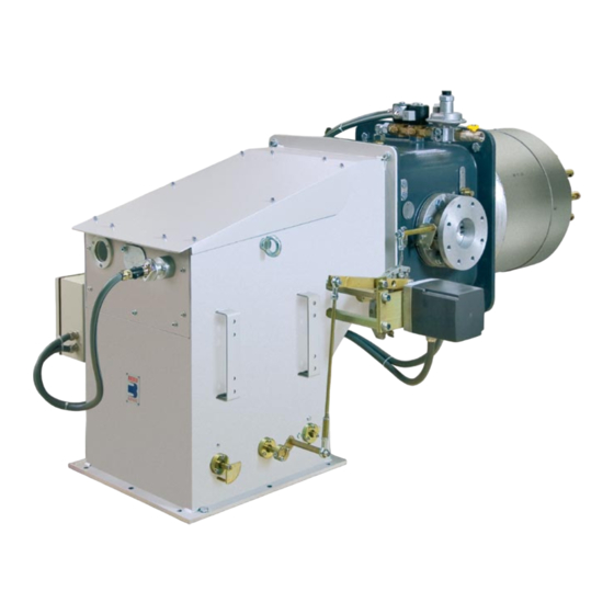
- Page 1 Installation, use and maintenance instructions Dual fuel light oil/gas burner Two stage progressive or modulating operation CODICE - CODE MODELLO - MODEL 20163106 DB 16 LSE FGR 20163598 (1) - 04/2019...
- Page 2 Original instructions...
-
Page 3: Table Of Contents
Contents Information and general warnings............................3 Information about the instruction manual ........................3 1.1.1 Introduction.................................. 3 1.1.2 General dangers................................3 1.1.3 Other symbols ................................3 1.1.4 Delivery of the system and the instruction manual...................... 4 Guarantee and responsibility............................4 Safety and prevention................................5 Introduction.................................. - Page 4 Contents 4.15 FGR duct system ...............................27 4.16 Electrical wiring ................................28 4.16.1 Supply cables and external connections passage .....................28 Start-up, calibration and operation of the burner ........................29 Notes on safety for the first start-up ...........................29 Combustion head adjustment ............................29 Adjustments prior to ignition (light oil) ........................29 5.3.1 Nozzle ..................................29 Burner ignition (light oil) .............................29...
-
Page 5: Information And General Warnings
Information and general warnings Information and general warnings Information about the instruction manual 1.1.1 Introduction WARNING: MOVING PARTS The instruction manual supplied with the burner: This symbol indicates that you must keep limbs is an integral and essential part of the product and must not away from moving mechanical parts;... -
Page 6: Delivery Of The System And The Instruction Manual
Information and general warnings 1.1.4 Delivery of the system and the instruction The system supplier must carefully inform the user about: – the use of the system; manual – any further tests that may be required before activating the When the system is delivered, it is important that: system;... -
Page 7: Safety And Prevention
Safety and prevention Safety and prevention Introduction The burners have been designed and built in compliance with the type and pressure of the fuel, the voltage and frequency of the current regulations and directives, applying the known technical electrical power supply, the minimum and maximum deliveries for rules of safety and envisaging all the potential danger situations. -
Page 8: Technical Description Of The Burner
Technical description of the burner Technical description of the burner Burner designation Range: DB Size: 4 - 6 - 9 - 12 - 16 - 20 Fuel: Gas oil Heavy oil Assisted atomisation heavy oil Natural Gas Light oil/ LPG Light oil / Natural gas Heavy oil / LPG Heavy Oil / Natural Gas... -
Page 9: Models Available
Technical description of the burner Models available Designation Voltage Code DB 16 LSE FGR FS1 A0 T150 TC 230V / 50-60Hz 20163106 Tab. A Burner categories - Countries of destination Country of destination Gas category SE - FI - AT - GR - DK - ES - GB - IT - IE - PT - IS - CH - NO 2ELL (43,46 ÷... -
Page 10: Maximum Dimensions
Technical description of the burner Maximum dimensions The maximum dimensions of the burner are given in Fig. 1. 20165206 Fig. 1 1151 1330 Tab. E Flange dimensions Air duct connection Boiler fixing Gas feeding 6 2 0 D B 2 0 5 1 0 5 6 0 D B 1 6 4 1 0... -
Page 11: Firing Rate
Technical description of the burner Firing rate The MAXIMUM OUTPUT is chosen from within the continuous The firing rate value (Fig. 3) has been obtained diagram area (Fig. 3). considering an ambient temperature of 20 °C, an The MINIMUM OUTPUT should never be less than 3000 kW as atmospheric pressure of 1013 mbar (approx. -
Page 12: Air Side Pressure Drop (Detected Upline Of The Damper With Complete Opening)
Technical description of the burner 3.10 Air side pressure drop (detected upline of the damper with complete opening) The pressure curves refer to the combustion head adjustment From the diagram, for an output of 9000 kW, the total pressure drop obtained at the head is equal to: p conditions according. -
Page 13: Gas Side Pressure Drops
Technical description of the burner 3.11 Gas side pressure drops Gas pressure on the basis of the maximum output developed by the burner is given by the curves in Fig. 6. Add the pressure of the combustion chamber in It represents the pressure drop in the combustion head. mbar to the value of the combustion head drop. -
Page 14: Description Of Burner Components
Technical description of the burner 3.12 Description of burner components 20165207 Fig. 8 kEY (Fig. 8) Electrical panel 17 Air damper position indicator Air box 18 Oil delivery pressure gauge Cover 19 Min. pressure switch in oil delivery Maximum gas pressure switch 20 Oil safety valve in delivery Gas output regulator 21 Oil safety valve on return... -
Page 15: Servomotor (Sqm48.4
Technical description of the burner 3.14 Servomotor (SQM48.4..) Warnings To avoid accidents, material or environmen- tal damage, observe the following instruc- tions! WARNING Avoid opening, modifying or forcing the ac- tuators. All interventions (assembly and installation operations, assistance, etc.) must be carried out by qualified personnel. ... -
Page 16: Azl Display
The AZL ... display is a safety device! Avoid open- WARNING ing or modifying it, or forcing its operation. Riello S.p.A. cannot assume any responsibility for dam- age resulting from unauthorised interventions! The electronic cam is operated and programmed through the AZL5 interface... -
Page 17: Control Box For The Air/Fuel Ratio (Lmv51
Technical description of the burner 3.16 Control box for the air/fuel ratio (LMV51...) Warnings – avoid conditions that can favour the development of conden- sate and humidity. Otherwise, before switching on again, To avoid accidents, material or environmental make sure that the entire control box is perfectly dry! damage, observe the following instructions! –... - Page 18 Technical description of the burner Electrical wiring of the flame detector – Line capacitance reduces the magnitude of the flame signal. – Use a separate cable. It is important for signal transmission to be almost totally free of any disturbances or loss: •...
-
Page 19: Installation
Installation Installation Notes on safety for the installation After carefully cleaning all around the area where the burner is to The installation of the burner must be carried out be installed, and arranging for the environment to be illuminated by qualified personnel, as indicated in this manual correctly, proceed with the installation operations. -
Page 20: Operating Position
Installation Operating position The burner is set up to work only in positions Any other position could compromise the cor- 1 and 4 (Fig. 13). rect operation of the appliance. Installation 1 is preferable, as it is the only ... -
Page 21: Lifting Points
Installation Lifting points Prepare a suitable lifting system using the rings shown in Fig. 16. Fig. 16 20165209 Boiler fixing The picture Fig. 17 indicates how to attach the burner to a boiler REFRACTORY equipped with a non-cooled frontal piece. It is recommended that the head protrusion should not exceed 200 mm. -
Page 22: Access To Head Internal Part
Installation Access to head internal part To access the inside of the combustion head (Fig. 18) proceed remove the plate 6); as follows: remove the electrical wiring 7) of the pilot; remove the cover of the air conveyor 1) and the plate 3); ... -
Page 23: Nozzles
Bergonzo type CT5 angle 45° (300 - 1500 kg/h). In order to guarantee that emissions do not vary, recommended and/or alternative nozzles specified by Riello in the Instruction and warning booklet should be used. It is advisable to replace the nozzle once a year during periodical maintenance. -
Page 24: Light Oil Supply
Installation 4.13 Light oil supply Explosion danger due to fuel leaks in the pres- The fuel supply line must be installed by qualified ence of a flammable source. personnel, in compliance with current standards Precautions: avoid knocking, attrition, sparks and and laws. -
Page 25: Adjustment And Calibration Of The Oil Circuit And Of The Air Output
Installation 4.13.2 Adjustment and calibration of the oil circuit and of the air output The oil supply system requires that suction of the fuel occurs from a degassing tank, using a self-priming pump, and that the fuel is sent to the burner at the correct pressure. This pressure is calibrated using the regulator built into the pump (Fig. -
Page 26: Priming Pump (Example)
Installation 4.13.3 Priming pump (example) Before starting the burner, make sure that the tank return line is not clogged. Obstructions in the line could cause the sealing WARNING organ located on the pump shaft to break. In order for self-priming to take place, the screw 4) on the pump (Fig. -
Page 27: Gas Feeding
Installation 4.14 Gas feeding Explosion danger due to fuel leaks in the pres- ence of a flammable source. Precautions: avoid knocking, attrition, sparks and heat. Make sure the fuel interception tap is closed be- fore performing any operation on the burner. The fuel supply line must be installed by qualified personnel, in compliance with current standards and laws. -
Page 28: Gas Train
Installation 4.14.3 Gas train Approved according to standard EN 676 and provided separately Make sure that the gas train is properly installed from the burner. by checking for any fuel leaks. 4.14.4 Gas train installation The operator must use the required equipment during installation. -
Page 29: Fgr Duct System
Installation 4.15 FGR duct system – Normally the duct would connect to the stack as shown in be required on the bottom of the duct 8)(Fig. 30), to remove Fig. 30, with a 45° cut facing the flue gas flow and with the condensate. -
Page 30: Electrical Wiring
Installation 4.16 Electrical wiring Notes on safety for the electrical wiring The electrical wiring must be carried out with the electrical supply disconnected. Electrical wiring must be made in accordance with the regulations currently in force in the country of destination and by qualified personnel. -
Page 31: Start-Up, Calibration And Operation Of The Burner
Start-up, calibration and operation of the burner Start-up, calibration and operation of the burner Notes on safety for the first start-up The first start-up of the burner must be carried out Check the correct working of the adjustment, com- by qualified personnel, as indicated in this manual mand and safety devices. -
Page 32: Adjustments Prior To Ignition (Gas)
Start-up, calibration and operation of the burner Adjustments prior to ignition (gas) In addition, the following adjustments must also be made: Before starting up the burner, it is good practice to Slowly open the manual valves situated upstream from the adjust the gas train so that ignition takes place in gas train. -
Page 33: Burner Ignition
Start-up, calibration and operation of the burner Burner ignition The burner should light after having performed the above steps. The arrival of the gas at the pipe coupling is shown on the U-type pressure gauge (Fig. 33) or else with the aid of a digital pressure If the starting cycle finishes but the flame does not appear and the gauge on the pressure test point under the pipe coupling. -
Page 34: Pressure Switch Adjustment
Start-up, calibration and operation of the burner 5.10 Pressure switch adjustment 5.10.1 Air pressure switch Adjust the air pressure switch after performing all other burner adjustments with the air pressure switch set to the start of the scale (Fig. 35). With the burner operating at MAX. -
Page 35: Final Checks (With Burner Operating)
Start-up, calibration and operation of the burner 5.11 Final checks (with burner operating) Open the thermostat/pressure switch TL The burner must stop Open the thermostat/pressure switch TS Turn the gas maximum pressure switch knob to the mini- ... -
Page 36: Maintenance
Maintenance Maintenance Notes on safety for the maintenance The periodic maintenance is essential for the good operation, Before carrying out any maintenance, cleaning or checking oper- safety, yield and duration of the burner. ations: It allows you to reduce consumption and polluting emissions and to keep the product in a reliable state over time. -
Page 37: Flame Sensor Disassembling
Maintenance Burner GAS OPERATION Clean the outside of the burner. Gas leaks Make sure that there are no gas leaks on the pipe between the Check to make sure that no dust has accumulated inside the fan gas meter and the burner. or on its blades, as this condition will cause a reduction in the air flow rate and provoke polluting combustion. -
Page 38: Safety Components
6.2.5 Safety components The safety components must be replaced at the end of their life cycle indicated in Tab. R. The specified life cycles do not refer to the warranty terms indicated in the delivery or payment conditions. Safety component Life cycle 10 years or 250,000 Flame control... -
Page 39: Shutter Replacement
Maintenance 6.2.6 Shutter replacement Be careful about spilling fuel. For the shutter replacement proceed as follows: disconnect the purging pipe 1) from the air box 2) and the Put back everything in the reverse order; centre the shutter flexible oil hoses 3) and 4) be careful about spilling light oil;... -
Page 40: Opening The Burner
Maintenance Opening the burner Turn off the burner's power supply using the main Wait for the components in contact with heat system switch. sources to cool down completely. DANGER In order to reach inside the combustion head refer to paragraph “Access to head internal part”... -
Page 41: Faults - Possible Causes - Solutions
Faults - Possible causes - Solutions Faults - Possible causes - Solutions If faults arise in ignition or operations, the burner performs a In the event the burner stops, in order to prevent "safety stop", which is signalled by the red burner lockout LED. any damage to the installation, do not unblock the The display visualises alternately the lockout code and the rela- burner more than twice in a row. -
Page 42: Gas Operation
Faults - Possible causes - Solutions Gas operation Problem Possible cause Recommended remedy The burner does not start No electrical power supply Close all switches - Check connections A limiter or safety control device is open Adjust or replace Flame control lockout Release Control box fuse broken Replace it... -
Page 43: A Appendix - Electrical Panel Layout
Faults - Possible causes - Solutions Appendix - Electrical panel layout Index of layouts Indication of references Operational layout Operational layout Operational layout Operational layout Operational layout Operational layout Operational layout Operational layout Operational layout Electrical connections set by installer Electrical connections set by installer Indication of references / 1 . - Page 44 Appendice - Appendix 20163598...
- Page 45 Appendice - Appendix 20163598...
- Page 46 Appendice - Appendix 20163598...
- Page 47 Appendice - Appendix 20163598...
- Page 48 Appendice - Appendix 20163598...
- Page 49 Appendice - Appendix 20163598...
- Page 50 Appendice - Appendix 20163598...
- Page 51 Appendice - Appendix 20163598...
- Page 52 Appendice - Appendix 20163598...
- Page 53 Appendice - Appendix 20163598...
- Page 54 Appendice - Appendix 20163598...
- Page 55 Appendice - Appendix Wiring layout key Burner components Nozzle valve Boiler components Burner terminal board Clear contacts terminal board A4.1 Electronic cam Regulation probe terminal board A9.1 Control box display VSD terminal board B3.1 Filter FGR terminal board B3.2 230/24V feeder Pressure switch connectors Probe with output under current DC 4..20 mA XPGM...
- Page 56 RIELLO S.p.A. I-37045 Legnago (VR) Tel.: +39.0442.630111 http:// www.riello.it http:// www.riello.com Subject to modifications...
Need help?
Do you have a question about the DB 16 LSE FGR and is the answer not in the manual?
Questions and answers