Table of Contents
Advertisement
Quick Links
KA01529T/09/EN/01.21-00
71562442
2021-11-30
Products
Brief Operating Instructions
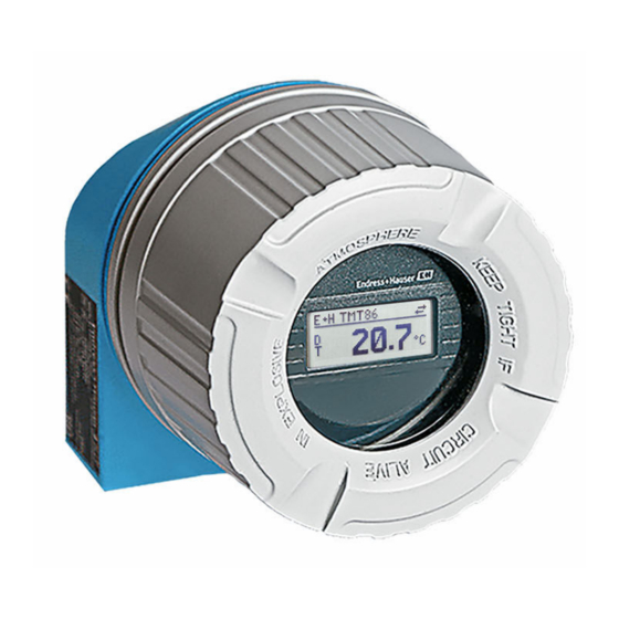
iTEMP TMT86
Dual-input temperature transmitter
PROFINET
®
protocol
These Instructions are Brief Operating Instructions; they are
not a substitute for the Operating Instructions pertaining to
the device.
For detailed information, refer to the Operating Instructions
and other documentation.
Available for all device versions via:
• Internet: www.endress.com/deviceviewer
• Smart phone/Tablet: Endress+Hauser Operations App
Solutions
Services
Advertisement
Table of Contents

Related Manuals for Endress+Hauser iTEMP TMT86


Summary of Contents for Endress+Hauser iTEMP TMT86
- Page 1 These Instructions are Brief Operating Instructions; they are not a substitute for the Operating Instructions pertaining to the device. For detailed information, refer to the Operating Instructions and other documentation. Available for all device versions via: • Internet: www.endress.com/deviceviewer • Smart phone/Tablet: Endress+Hauser Operations App...
- Page 2 TMT86 Order code: XXXXX-XXXXXX Ser. no.: XXXXXXXXXXXX Ext. ord. cd.: XXX.XXXX.XX Serial number www.endress.com/deviceviewer Endress+Hauser Operations App A0023555 Endress+Hauser...
-
Page 3: Table Of Contents
TMT86 Table of contents Table of contents About this document ............. . 3 Symbols used . -
Page 4: Tool Symbols
Safety instructions iTEMP TMT86 WARNING This symbol alerts you to a dangerous situation. Failure to avoid this situation can result in serious or fatal injury. CAUTION This symbol alerts you to a dangerous situation. Failure to avoid this situation can result in minor or medium injury. -
Page 5: Intended Use
TMT86 Safety instructions Intended use The device is a universal and user-configurable temperature transmitter with either one or two sensor inputs for a resistance thermometer (RTD), thermocouples (TC), resistance and voltage transmitters. The head transmitter version of the device is intended for mounting in a terminal head (flat face) as per DIN EN 50446. -
Page 6: Incoming Acceptance And Product Identification
(www.endress.com/deviceviewer): all data relating to the device and an overview of the Technical Documentation supplied with the device are displayed. • Enter the serial number on the nameplate into the Endress+Hauser Operations App or scan the 2-D matrix code (QR code) on the nameplate with the Endress+Hauser Operations App: all the information about the device and the technical documentation pertaining to the device is displayed. -
Page 7: Certificates And Approvals
TMT86 Installation Certificates and approvals For certificates and approvals valid for the device: see the data on the nameplate Approval-related data and documents: www.endress.com/deviceviewer → (enter the serial number) Storage and transport Storage temperature: –52 to +100 °C (–61.6 to +212 °F) Humidity •... -
Page 8: Mounting The Measuring Device
Installation iTEMP TMT86 • Condensation permitted with head transmitter • Max. rel. humidity: 95 % as per IEC 60068-2-30 • Degree of protection: • Head transmitter with screw terminals: IP00, with push-in terminals: IP30. When installed, the degree of protection depends on the terminal head or field housing used. -
Page 9: Post-Mounting Check
TMT86 Electrical connection Mounting typical of North America A0008520 2 Head transmitter mounting NOTICE The terminal head cover must be secured properly to meet the requirements for explosion protection. ‣ After wiring, securely screw the terminal head cover back on. -
Page 10: Connecting The Measuring Device
Electrical connection iTEMP TMT86 CAUTION ‣ Switch off the power supply before installing or connecting the device. Non-compliance may result in the destruction of parts of the electronics. ‣ When connecting Ex-certified devices, please take special note of the instructions and connection schematics in the Ex-specific supplement to these Operating Instructions. - Page 11 TMT86 Electrical connection • via conventional cable gland → 11 • via fieldbus device connector (optional, available as an accessory) Risk of damage • Switch off the power supply before installing or connecting the head transmitter. Non- compliance may result in the destruction of parts of the electronics.
-
Page 12: Connecting The Sensor Cables
Electrical connection iTEMP TMT86 Terminals Choice of screw or push-in terminals for sensor cables and supply cables. The terminals for connecting the fieldbus (1+ and 2-) are protected against reverse polarity. A shielded cable must be used for the connection. - Page 13 TMT86 Electrical connection NOTICE When connecting 2 sensors ensure that there is no galvanic connection between the sensors (e.g. caused by sensor elements that are not isolated from the thermowell). The resulting equalizing currents distort the measurements considerably. ‣...
-
Page 14: Ensuring The Degree Of Protection
Electrical connection iTEMP TMT86 5.3.1 Connecting to push-in terminals A0039468 5 Connecting to push-in terminals Ensuring the degree of protection Compliance with the following points is mandatory following installation in the field or servicing in order to ensure that IP67 protection is maintained: •... -
Page 15: Post-Connection Check
TMT86 Electrical connection A0024523 6 Connection tips to retain IP67 protection Post-connection check Device health and specifications Notes Are the device and cables undamaged (visual check)? Electrical connection Notes Does the port classification match the information on the... -
Page 16: Operation Options
Operation options iTEMP TMT86 Operation options Overview of operation options A0048408 Local operation via DIP switch on display module Computer with web browser (e.g. Internet Explorer) or with operating tool (e.g. FieldCare, SIMATIC PDM) Field Xpert SMT70 Control system (e.g. PLC) Temperature transmitter 6.1.1... - Page 17 TMT86 Operation options Option: Display TID10 for head transmitter The display can also be ordered later, see the "Accessories" section in the Operating Instructions for the device. A0010227 7 Attach the display to the transmitter Local operation NOTICE ‣...
-
Page 18: Access To Operating Menu Via Web Browser
Operating tools DeviceCare (Endress+Hauser) SIMATIC PDM (Siemens) FieldCare (Endress+Hauser) Field Device Manager FDM (Honeywell) Field Xpert SMT70 (Endress+Hauser) Fieldbus Information Manager FIM (ABB) Commissioning Post-installation check Before commissioning the measuring point make sure that all final checks have been carried out: •... -
Page 19: Maintenance
TMT86 Maintenance Maintenance No special maintenance work is required for the device. Cleaning A clean, dry cloth can be used to clean the device. Endress+Hauser... - Page 20 *71562442* 71562442 www.addresses.endress.com...
Need help?
Do you have a question about the iTEMP TMT86 and is the answer not in the manual?
Questions and answers