
Related Manuals for AFRISO AG 11


Summary of Contents for AFRISO AG 11
- Page 1 Betriebsanleitung Operating instructions AG 11 AG 12 Copyright 2023 AFRISO-EURO-INDEX GmbH. Alle Rechte vorbehalten. Version: 05.2023.0 ID: 900.000.1080...
- Page 2 Betriebsanleitung Alarmgerät AG 11 AG 12 Copyright 2023 AFRISO-EURO-INDEX GmbH. Alle Rechte vorbehalten. Version: 05.2023.0 ID: 900.000.1080...
-
Page 3: Über Diese Betriebsanleitung
Über diese Betriebsanleitung Über diese Betriebsanleitung Diese Betriebsanleitung beschreibt die Alarmgeräte AG 11 und AG 12 (im Folgenden auch „Produkt“). Diese Betriebsanleitung ist Teil des Produkts. • Sie dürfen das Produkt erst benutzen, wenn Sie die Betriebsanleitung vollständig gelesen und verstanden haben. - Page 4 Sie alle im Zusammenhang mit diesem Warnsymbol beschriebenen Hinweise, um Unfälle mit Todesfolge, Verlet- zungen und Sachschäden zu vermeiden. Dieses Symbol warnt vor gefährlicher elektrischer Span- nung. Wenn dieses Symbol in einem Warnhinweis gezeigt wird, besteht die Gefahr eines elektrischen Schlags. AG 11 / AG 12...
-
Page 5: Informationen Zur Sicherheit
Das Produkt darf insbesondere in folgenden Fällen und für folgende Zwecke nicht angewendet werden: • Explosionsgefährdete Umgebung - Bei Betrieb in explosionsgefährdeten Bereichen kann Funkenbildung zu Verpuffungen, Brand oder Explosionen führen. • In Räumen, in denen hohe Luftfeuchtigkeit entstehen kann (beispiels- weise Badezimmer) AG 11 / AG 12... -
Page 6: Transport Und Lagerung
Benutzen Sie für den Transport die Originalverpackung. • Lagern Sie das Produkt nur in trockener, sauberer Umgebung. • Stellen Sie sicher, dass das Produkt bei Transport und Lagerung stoßge- schützt ist. Nichtbeachtung dieser Anweisungen kann zu Sachschäden führen. AG 11 / AG 12... - Page 7 Wird der Kontakt eines angeschlossenen Signalgebers geschlossen, gibt das Produkt einen optischen und akustischen Alarm. Im Alarmfall werden die potenzialfreien Wechselkontakte geschaltet. AG 11 AG 12 Abbildung 1: Anschluss des Signalgebers an die Alarmgeräte AG 11 und AG 12 AG 11 / AG 12...
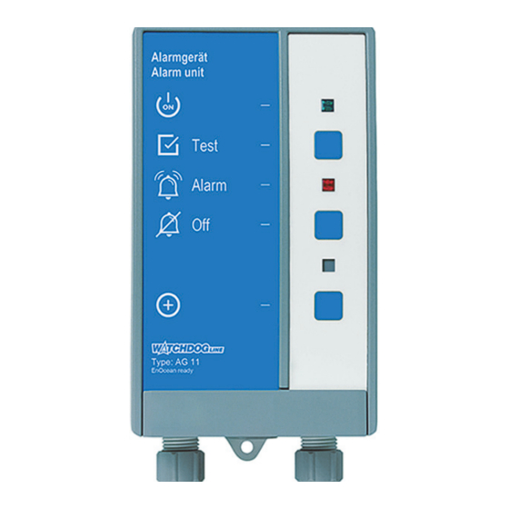
- Page 8 Wiedergabe der Alarmsignale und das Schalten der potenzialfreien Wech- selkontakte. A. Bezeichnung des Pro- dukts B. Grüne LED C. Test-Taste D. Rote LED E. Quittiertaste/ Stummschalttaste F. Ohne Funktion G. LRN-Taste Abbildung 2: Übersicht AG 11 AG 11 / AG 12...
- Page 9 Mit dieser Taste wird der akustische Alarm stummge- schaltet und der quittierbare potenzialfreie Wechsel- kontakt (AG 12) abgeschaltet. Taste Mit der LRN-Taste sendet das Produkt ein Lern-Tele- gramm (LRNTEL), um sich mit dem AFRISOhome Gateway zu verbinden. AG 11 / AG 12...
- Page 10 Produktbeschreibung Abmessungen Abbildung 3: Abmessungen in mm AG 11 / AG 12...
- Page 11 G. Anschlussklemmen für Signalgeber (Sonde) AG 12 A. Anschlussklemmen für Spannungsversorgung B. Potenzialfreier Wechsel- kontakt C. Potenzialfreier Wechsel- kontakt (quittierbar) D. Anschlussklemmen für externe Quittierung E. Anschlussklemmen für Signalgeber (Sonde) F. Steckplatz für das EnOcean®-Funkmodul AG 11 / AG 12...
- Page 12 Anwendungsbeispiel Abbildung 4: Absicherung des Heizkessels bei zu niedrigem Wasserstand. Bei einem Wassermangel erkennt die Wassermangelsicherung WMS-WP6 (B) diesen Zustand. Das Alarmgerät AG 11 (A) gibt Alarm und schaltet den potenzialfreien Wechselkontakt, die Rundumleuchte SLD 1 (C) (optional) wird aktiviert.
- Page 13 Das Produkt gibt den Alarm eines Signalgebers wieder. Der Alarm wird optisch und akustisch angezeigt. Bei einem Alarm leuchtet die rote LED dau- erhaft und der akustische Alarm ertönt. Der akustische Alarm kann durch Drücken der Quittiertaste stumm geschaltet werden. AG 11 / AG 12...
- Page 14 Die Produkte können ohne und mit zusätzlichen Geräten betrieben werden, beispielsweise: • Optische und akustische Alarmgeber • Fernmeldegeräte • Gebäudeleittechnik Zulassungsdokumente, Bescheinigungen, Erklärungen Das Produkt entspricht: • EMV-Richtlinie (2014/30/EU) • Niederspannungsrichtlinie (2014/35/EU) • RoHS-Richtlinie (2011/65/EU) AG 11 / AG 12...
- Page 15 Schaltvermögen des potenzi- Maximal 250 V, 2 A, ohmsche Last alfreien Wechselkontaktes Signalgeber Anschluss Maximal AC 17 V DC 12 V Netzsicherung T 100 mA Relaissicherung T 2 A Schutzklasse (EN 60730) Schutzart (EN 60529) IP 30 AG 11 / AG 12...
- Page 16 EnOcean®- Equipment Pro- A5-30-04 file (EEP) Gummitülle durch Kabelverschraubung ersetzen Bei einem fest verlegten Kabel kann die am Produkt vorhandene mittlere Gummi- tülle verwendet werden. Verschraubung Kabeldurchmesser 4,0 … 8,8 mm 8,0 … 12,5 mm AG 11 / AG 12...
-
Page 17: Montage
Nichtbeachtung dieser Anweisungen kann zu Sachschäden führen. Produkt montieren Befestigen Sie das Produkt an einer ebenen, festen und trockenen Wand (Variante A oder B verwenden). Stellen Sie sicher, dass das Produkt jederzeit zugänglich und einsehbar ist. AG 11 / AG 12... - Page 18 (Variante A oder B ver- wenden). Variante A 1. Befestigen Sie die Schraube an der Wand. 2. Hängen Sie das Produkt ein. 3. Befestigen Sie das Pro- dukt an der Wand mit einer Schraube an der unteren Lasche. AG 11 / AG 12...
- Page 19 Unterteil. 2. Befestigen Sie das Pro- dukt an der Wand mit den beiliegenden Schrauben. 3. Schließen Sie das Pro- dukt, wie in Kapitel "Elekt- rischer Anschluss" beschrieben, an. 4. Schließen Sie das Pro- dukt. AG 11 / AG 12...
- Page 20 Montage Betriebsart festlegen (nur AG 11) Das Produkt ist werksseitig auf die Betriebsart „Öko“ eingestellt. Wenn Sie das Produkt in der Betriebsart „FailSafe“ verwenden möchten, müssen Sie die Steckbrücke (Jumper) auf der Platine umstecken. 1. Öffnen Sie das Produkt. 2. Stecken Sie die Steckbrücke (Jumper) auf die Kontakte für die einzu- stellende Betriebsart.
- Page 21 NICHTVERFÜGBARKEIT DER ÜBERWACHUNGSFUNKTION • Installieren Sie keine Netzstecker oder Schalter in der Spannungsversor- gung für das Produkt. • Schalten Sie das Produkt nur über die bauseitige Netzsicherung ein und aus. Nichtbeachtung dieser Anweisungen kann zu Sachschäden führen. AG 11 / AG 12...
- Page 22 Stellen Sie sicher, dass das Signalgeberkabel nicht direkt neben oder zusammen mit Kabeln verlegt wird, die Netzspannung führen. 1. Führen Sie das Signalgeberkabel durch die rechte Kabelverschrau- bung. 2. Schließen Sie die Adern des Signalgeberkabels an die Anschlussklem- men mit der Bezeichnung „Sonde“ an. AG 11 / AG 12...
- Page 23 2. Schließen Sie zusätzliche Geräte an die Anschlussklemmen „Alarm“ oder die Anschlussklemmen „Alarm Quit.“ (nur AG 12) an. - Informationen zur Verwendung zusätzlicher Geräte entnehmen Sie der Anleitung des Herstellers. AG 11 AG 12 Abbildung 7: Anschlussklemmen der potenzialfreien Wechselkontakte AG 11 / AG 12...
- Page 24 Folgendes sicher: - Alle Pins müssen in die Buchsenleiste gesteckt sein. - Die Antenne muss auf der rechten Seite entlang der Gehäusewand in die Führung (A) geklemmt sein. 3. Schließen Sie den Deckel des Produkts wieder. AG 11 / AG 12...
- Page 25 Funktionsprüfung über Signalgeber durchführen Bringen sie den Signalgeber in eine Alarm-Situation. - Die rote LED leuchtet. - Der akustische Alarm ertönt. Beenden sie die Alarm-Situation des Signalgebers. - Der optische und akustische Alarm muss selbsttätig erlöschen. AG 11 / AG 12...
-
Page 26: Betrieb
Einmal jährlich und Tauschen Sie beschädigte Teile. nach Alarmfall Führen Sie eine Funktionsprüfung durch (siehe "Funktionsprüfung durchführen"). Bei Bedarf Reinigen Sie das Produkt mit einem leicht ange- feuchteten Tuch. Verwenden Sie eine milde Sei- fenlauge. AG 11 / AG 12... -
Page 27: Fehlerbehebung
Leitungsunterbrechung Prüfen Sie das Kabel Rote LED leuchtet nicht Produkt defekt Bitte wenden Sie sich an und der akustische die AFRISO-Service Alarm ertönt nicht, Hotline obwohl Signalgeber geschaltet hat Sonstige Störungen Bitte wenden Sie sich an die AFRISO-Service Hotline AG 11 / AG 12... - Page 28 4. Stecken Sie die transparente Abdeckung wieder auf. 5. Schließen Sie das Produkt. 6. Schalten Sie die Netzspannung ein. Störungen, die nicht durch die im Kapitel beschriebenen Maßnahmen besei- tigt werden können, dürfen nur durch den Hersteller behoben werden. AG 11 / AG 12...
-
Page 29: Außerbetriebnahme Und Entsorgung
Rücksendung Vor einer Rücksendung Ihres Produkts müssen Sie sich mit uns in Verbin- dung setzen (service@afriso.de). Gewährleistung Informationen zur Gewährleistung finden Sie in unseren Allgemeinen Geschäftsbedingungen im Internet unter www.afriso.com oder in Ihrem Kauf- vertrag. AG 11 / AG 12... -
Page 30: Ersatzteile Und Zubehör
Nichtbeachtung dieser Anweisung kann zu Sachschäden führen. Produkt Artikelbezeichnung Art.-Nr. Abbildung Alarmgerät AG 11 67030 Alarmgerät AG 12 67031 Ersatzteile und Zubehör Artikelbezeichnung Art.-Nr. EnOcean®-Funkmodul TCM 320 78082 Kabelverlängerungsarmatur KVA 40041 Montagerahmen 43521 IP54-Set mit Verschraubung M20 43416 Montageset Hutschienenclip 43100 AG 11 / AG 12... - Page 31 Funkstandard • Funktechnologie • AN001 • AN102 • AN103 • AN201 14.3 Möglichkeiten der EnOcean®-Technologie Unterlagen über EnOcean®-Technologien finden Sie im Internet unter www.afrisohome.de. Auf unserem YouTube-Channel finden Sie eine Reihe von Videos zu AFRISO-Produkten. AG 11 / AG 12...
- Page 32 Anhang Anhang 15.1 EU-Konformitätserklärung AG 11 / AG 12...
-
Page 33: Alarm Unit
Operating instructions Alarm unit AG 11 AG 12 Copyright 2023 AFRISO-EURO-INDEX GmbH. All rights reserved. Version: 05.2023.0 ID: 900.000.1080... - Page 34 About these operating instructions About these operating instructions These operating instructions describe the alarm units AG 11 and AG 12 (also referred to as "product" in these operating instructions). These operating instructions are part of the product. • You may only use the product if you have fully read and understood these operating instructions.
- Page 35 This symbol alerts to hazardous electrical voltage. If this symbol is used in a safety message, there is a hazard of electric shock. AG 11 / AG 12...
-
Page 36: Information On Safety
The product must never be used in the following cases and for the following purposes: • Hazardous area (Ex) - If the product is operated in hazardous areas, sparks may cause defla- grations, fires or explosions. • In rooms that are subject to high humidity (such as bathrooms) AG 11 / AG 12... -
Page 37: Transport And Storage
Store the product in a clean and dry environment. • Verify that the product is protected against shocks and impact during trans- port and storage. Failure to follow these instructions can result in equipment damage. AG 11 / AG 12... - Page 38 In the case of an alarm, the voltage-free changeover contacts are switched. AG 11 AG 12 Fig. 1: Connection of the signal transmitter to the alarm units AG 11 and AG 12 AG 11 / AG 12...
-
Page 39: Product Description
A. Designation of product B. Green LED C. Test key D. Red LED E. Acknowledge key/ mute key F. Without function G. LRN key Fig. 2: Overview AG 11 AG 11 / AG 12... - Page 40 This key is used to mute the audible alarm and to switch off the acknowledgeable, voltage-free change- over contact (AG 12). If the LRN key is pressed, the product sends a LRN telegram (LRNTEL) to connect to the AFRISOhome gateway. AG 11 / AG 12...
- Page 41 Product description Dimensions Fig. 3: Dimensions in mm AG 11 / AG 12...
- Page 42 A. Connection terminal for power supply B. Voltage-free changeover contact C. Voltage-free changeover contact (acknowledgeable) D. Connection terminal for external acknowledgement E. Connection terminals for signal transmitter (probe) F. Slot for EnOcean® wireless module AG 11 / AG 12...
-
Page 43: Application Example
The boiler water low level alarm WMS-WP6 (B) detects a low water level in the boiler. The alarm unit AG 11 (A) triggers an alarm and switches the volt- age-free changeover contact, the warning light with rotating reflector SLD 1 (C) (optional) is activated. - Page 44 The product reproduces the alarm of a signal transmitter. The product trig- gers visual and audible alarms. In the case of an alarm, the red LED is per- manently illuminated and the audible alarm is activated. The audible alarm can be muted with the Acknowledge key. AG 11 / AG 12...
- Page 45 • Visual and audible alarm units • Remote alarm equipment • Building control systems Approvals, conformities, certifications The product complies with: • EMC Directive (2014/30/EU) • Low Voltage Directive (2014/35/EU) • RoHS Directive (2011/65/EU) AG 11 / AG 12...
-
Page 46: Technical Specifications
Maximum 250 V, 2 A, resistive load age-free changeover contact Signal transmitter connection Maximum AC 17 V DC 12 V Mains fuse T 100 mA Relay fuse T 2 A Protection class (EN 60730) Degree of protection (EN IP 30 60529) AG 11 / AG 12... - Page 47 Replacing the rubber piece by a cable gland In the case of a permanently installed cable, you can use the centre rubber piece Screw connection Cable diameter 4.0 … 8.8 mm 8.0 … 12.5 mm AG 11 / AG 12...
-
Page 48: Mounting The Product
Mounting the product Mount the product to a plane, rigid and dry wall at eye level (use mounting type A or B). Verify that the product is accessible and easy to oversee at all times. AG 11 / AG 12... - Page 49 2. Mount the housing to the wall using mounting type A or B. Mounting type A 1. Mount the screw to the wall. 2. Fit the product. 3. Fasten the product by screwing the bottom lug to the wall. AG 11 / AG 12...
- Page 50 1. Drill two fixing holes with a Ø 5 mm into the base. 2. Mount the product to the wall with the enclosed screws. 3. Connect the product as described in chapter "Electrical connection". 4. Close the product. AG 11 / AG 12...
- Page 51 Mounting Setting the operating mode (AG 11 only) The product is factory-set to the operating mode "Eco". If you want to operate the product in the operating mode "FailSafe", you must change the position of the jumper on the PCB.
-
Page 52: Electric Shock
Do not install mains plugs or switches in the supply line to the product. • Only power on/power off the product via the on-site mains fuse. Failure to follow these instructions can result in equipment damage. AG 11 / AG 12... -
Page 53: Supply Voltage
1. Route the signal transmitter cable through the cable gland at the right. 2. Connect the wires of the signal transmitter cable to the connection ter- minal with the designation "Sonde". AG 11 / AG 12... - Page 54 "Alarm Quit." (AG 12 only). - Refer to the operating instructions of the manufacturer of the additional equipment for further information. AG 11 AG 12 Fig. 7: Connection terminals of the voltage-free changeover contacts AG 11 / AG 12...
-
Page 55: Electrostatic Discharge
- All pins must be inserted into the female connec- tor. - The antenna must be located in the guide (A) along the housing wall. 3. Close the cover of the product. AG 11 / AG 12... - Page 56 Set the signal transmitter to an alarm condition. - The red LED lights. - The audible alarm sounds. Terminate the alarm condition of the signal transmitter. - The audible alarm and the visual alarm must switch off automatically. AG 11 / AG 12...
-
Page 57: Operation
Activity Once per year and after Replace damaged parts. an alarm Perform a function test (see "Performing the func- tion test"). If required Clean the product with a slightly damp cloth. Use mild soap suds. AG 11 / AG 12... -
Page 58: Troubleshooting
Check the cable Red LED is off and the Product defective Contact the AFRISO audible alarm does not service hotline sound, even though the signal transmitter has switched Other malfunctions Contact the AFRISO service hotline AG 11 / AG 12... - Page 59 4. Refit the transparent cover. 5. Close the product. 6. Apply mains voltage. Any malfunctions that cannot be removed by means of the measures described in this chapter may only be repaired by the manufacturer. AG 11 / AG 12...
-
Page 60: Decommissioning / Disposal
3. Dispose of the product. Returning the device Get in touch with us before returning your product (service@afriso.de). Warranty See our terms and conditions at www.afriso.com or your purchase contract for information on warranty. AG 11 / AG 12... -
Page 61: Spare Parts And Accessories
Spare parts and accessories Product designation Part no. EnOcean® wireless module TCM 320 78082 Cable extension fitting KVA 40041 Mounting frame 43521 IP54 kit with cable gland M20 43416 Mounting kit DIN rail clip 43100 AG 11 / AG 12... - Page 62 • AN102 • AN103 • AN201 14.3 Features of the EnOcean® technology Visit www.afrisohome.de for documents on EnOcean® technologies. A variety of videos on AFRISO products can also be found on the AFRISO YouTube channel. AG 11 / AG 12...
- Page 63 Appendix Appendix 15.1 EU Declaration of Conformity AG 11 / AG 12...
Need help?
Do you have a question about the AG 11 and is the answer not in the manual?
Questions and answers