Table of Contents
Advertisement
Quick Links
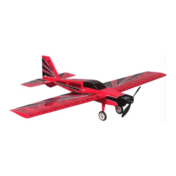
Hornet
The
KIT # K-107
Assembly Instructions
WARRANTY
Alien Aircraft Corp. guarantees this kit to be free from defects in both material and workmanship at the date of purchase. This warranty does not
cover any component parts damaged by use or modification. In no case shall Alien Aircraft Corp.s' liability exceed the original cost of the purchased
kit. Further, Alien Aircraft Corp. reserves the right to change or modify this warranty without notice. The quality and flyability of your finished
model depends on how you build it; therefore, we cannot in any way guarantee the performance of your completed model, and no representations are
expressed or implied as to the performance or safety of your completed model.
In that Alien Aircraft Corp. has no control over the final assembly or material used for final assembly, no liability shall be assumed nor accepted for
any damage resulting from the use by the user of the final user-assembled product. By the act of using the user-assembled product, the user accepts
all resulting liability. If the buyer is not prepared to accept the liability associated with the use of this product, the buyer is advised to return this kit
immediately in new and unused condition to the place of purchase.
WARNING!!!
Failure to follow these safety precautions may result in severe injury to yourself and others.
Use safety glasses when running the motor. Do not run the motor in an area of loose gravel or sand; the propeller may throw such material in your
face or eyes. Keep your face and body as well as all spectators away from the plane of rotation of the propeller as you run the motor. Keep these
items away from the prop: loose clothing, shirt sleeves, ties, scarfs, long hair or loose objects such as pencils or screwdrivers that may fall out of
shirt or jacket pockets into the prop. Always remove the LiPo battery from the plane before charging. Always use a charger designed to charge LiPo
batteries for charging the LiPo flight battery. Never leave the LiPo battery unattended while charging. If the battery becomes more than just warm,
discontinue charging.
Alien Aircraft Corp.
TM
403-A Flomich Street
Holly Hill, FL. 32117
(386)676-0074
© 2010 Alien Aircraft Corp
Advertisement
Table of Contents

Related Manuals for Alien Aircraft Corp Hornet K-107


Summary of Contents for Alien Aircraft Corp Hornet K-107
- Page 1 In that Alien Aircraft Corp. has no control over the final assembly or material used for final assembly, no liability shall be assumed nor accepted for any damage resulting from the use by the user of the final user-assembled product. By the act of using the user-assembled product, the user accepts all resulting liability.
-
Page 2: Kit Contents
Notes about the laser cut parts 1...The first thing that you need to do is to identify and mark the part numbers on the laser cut parts using the drawings on the following pages as a guide. 2...It is possible that several of the laser cut parts may not be completely cut through. If this is the case you can free the part from the sheet quickly using an X-acto knife. - Page 3 May be 1/32” x 3” x 12” Page 3...
-
Page 4: Building Instructions
Building Instructions: General Note: Cover the plans with wax paper before assembling your model to prevent the parts from sticking to the plan. Building the Tail Surfaces: 1...Glue R-1 and R-2 together. Glue R-3 and R-4 together. Sand the outside edges round. Leave the fuselage edges square. Bevel the front edge of R-5 as shown on the plan, and sand the other edges round. - Page 5 5...Lightly tack glue formers F-3 , F-4, F-5 and F-6 into position on the right fuselage side. Use a small square to position these parts 90 degrees to the fuselage side. 6...Place the left fuselage side into position and square up the fuselage. Glue the left fuselage to the formers.
- Page 6 10...Place the landing gear wire into the fuselage tightly against the front of F-3. Glue securely into position. Flush 11...Glue parts F-9L and F-9R into position. These parts should be flush with the notches in the fuselage side. 12...Glue F-10 into position. It should fit down into the notches in parts F-2 and F-9.
- Page 7 15...Glue F-13 to the top of the fuselage. Slightly wet the outside of the part to allow it to curve / bend easier. 16...Pull and glue the rear of the fuselage sides together. 17...Slide former F-14 into position. Adjust the back end until the fuselage is straight and square.
- Page 8 20...Glue F-16 into position on the bottom rear of the fuselage. 21...Glue F-17 into position on the top of the fuselage. Building the Hatch: 22...Glue parts H-2, H-3 and H-4 into position on the hatch (H-1) using the laser marking as a guide. Glue parts H-5 and H-6 together. Make sure that they are 90 degrees to each other.
-
Page 9: Building The Wing
25...Test fit the hatch to the bottom of the fuselage. The front tab (H-2) slides under part F-11. Slide the hatch slider forward and press the back end of the hatch down on the fuselage. Move the slider back to insert it into the slot in former F-6. You can trim the outside edges of H-2 to center the front of the hatch if required. - Page 10 31...Slide the lower 1/16” x 1/2” trailing edge into position in the slots between the ribs and their support tabs. After making sure that it is positioned properly, glue to the ribs. 32...Glue the 3/32” x 3/16” top spar and the 1/4” sq. leading edge into position.
- Page 11 36...Use two of the 1/32” x 1 1/2” sheets to sheet the center of the wing. The sheet should be cut to fit between the spars as shown on the plan. 37...Glue W-10 into position to the spar and rib W-3. 38...Remove the wing from the plan.
- Page 12 41...Glue two W-11 ribs to the end of the wing. 42...Sand the leading edge round to match the profile shown on the plan. Now sand the wing smooth all over. 43...Now repeat steps 27 thru 42 to build the left wing. 44...Sand the back edges and the ends of the ailerons round.
-
Page 13: Final Assembly
Covering: 47...Sand all parts smooth with 400 grit sandpaper. Cover the model with a light weight iron on covering material. Note: After the model is covered you must check the tail surfaces and wings for warps or twists. If there are any they can be removed by twisting the parts straight and heating the covering. - Page 14 53...Screw the servos to the servo tray. 54...Glue the rudder and elevator control horns into position. Drill 1/16” holes for the pins to pass thru. When the glue is dry, cut off the excess pins flush.. 55...Install the pushrods into the housings. Secure the rear of the pushrods with Mini E/Z Links.
- Page 15 57...Screw the servos into position on the bottom of the wing. Feed the servo wires through the holes in ribs W-2 and W-1. 58...Glue the aileron control horns into position. Drill 1/16” holes for the pins to pass thru. When the glue is dry, cut off the excess pins flush.
- Page 16 63...Attach parts LG to the back of the landing gear wires with a small amount of C/A. Wrap a 1/2” wide strip of covering material around the front of the landing gear wire and iron into position to secure parts LG to the landing gear wire.
- Page 17 68...WITH THE PROPELLER REMOVED...Turn the transmitter on. Place the throttle stick in the low position. Plug the battery into the speed controller. Check the motor for proper operation and direction of rotation. Follow the instructions with the speed controller to make any adjustments. 69...Check the servos for proper operation and direction.
Need help?
Do you have a question about the Hornet K-107 and is the answer not in the manual?
Questions and answers