Advertisement
Quick Links
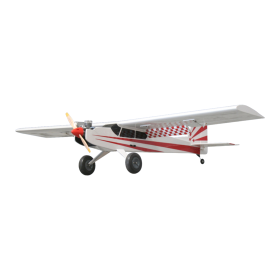
FunMaster 72
KIT # K-504
Assembly Instructions
Version 2 11-15-13
WARRANTY
Alien Aircraft Corp. guarantees this kit to be free from defects in both material and workmanship at the date of purchase. This warranty does not
cover any component parts damaged by use or modification. In no case shall Alien Aircraft Corp.s' liability exceed the original cost of the purchased
kit. Further, Alien Aircraft Corp. reserves the right to change or modify this warranty without notice. The quality and flyability of your finished
model depends on how you build it; therefore, we cannot in any way guarantee the performance of your completed model, and no representations are
expressed or implied as to the performance or safety of your completed model.
In that Alien Aircraft Corp. has no control over the final assembly or material used for final assembly, no liability shall be assumed nor accepted for
any damage resulting from the use by the user of the final user-assembled product. By the act of using the user-assembled product, the user accepts
all resulting liability. If the buyer is not prepared to accept the liability associated with the use of this product, the buyer is advised to return this kit
immediately in new and unused condition to the place of purchase.
WARNING!!!
Failure to follow these safety precautions may result in severe injury to yourself and others.
Use safety glasses when running the motor. Do not run the motor in an area of loose gravel or sand; the propeller may throw such material in your
face or eyes. Keep your face and body as well as all spectators away from the plane of rotation of the propeller as you run the motor. Keep these
items away from the prop: loose clothing, shirt sleeves, ties, scarfs, long hair or loose objects such as pencils or screwdrivers that may fall out of
shirt or jacket pockets into the prop. Always remove the LiPo battery from the plane before charging. Always use a charger designed to charge LiPo
batteries for charging the LiPo flight battery. Never leave the LiPo battery unattended while charging. If the battery becomes more than just warm,
discontinue charging.
Alien Aircraft Corp.
403-A Flomich Street
Holly Hill, FL. 32117
© 2013 Alien Aircraft Corp
(386)676-0074
Advertisement

Related Manuals for Alien Aircraft Corp FunMaster 72 K-504


Summary of Contents for Alien Aircraft Corp FunMaster 72 K-504
-
Page 1: Assembly Instructions
In that Alien Aircraft Corp. has no control over the final assembly or material used for final assembly, no liability shall be assumed nor accepted for any damage resulting from the use by the user of the final user-assembled product. By the act of using the user-assembled product, the user accepts all resulting liability. - Page 2 Notes about the laser cut parts 1...The first thing that you need to do is to identify and mark the part numbers on the laser cut parts using the drawings on the following pages as a guide. 2...It is possible that several of the laser cut parts may not be completely cut through. If this is the case you can free the part from the sheet quickly using an X-acto knife.
- Page 3 Misc. Loose Parts 4 ..Wing Leading Edge Sheet ...3/32” x 4” x 36” Balsa Hardware Bag Qty..Name ........Description 1 .
- Page 4 Additional Items Required for Glow Power Only (Not Included in Kit) Qty. .Name ....Description 1 ..Motor ....2-stroke .50-.65 4-stroke .50-.65 1 .
- Page 5 Page 5...
- Page 6 Page 6...
- Page 7 Page 7...
- Page 8 Page 8...
-
Page 9: Building Instructions
Building Instructions: General Note: Cover the plans with wax paper before assem- bling your model to prevent the parts from sticking to the plan. Building the Tail Surfaces: 1... Glue R-1, R-2, and R-3 together as shown. 2...Glue S-1 and S-2 together. 3...Glue together two pieces of 1/16”... - Page 10 5...Use 1/16” balsa to sheet both sides of the elevators (S-3). Use 1/16” balsa to sheet both sides of the rudder (R-4). 6...Bevel the front edge of R-4 as shown on the plan, and sand the other edges of the fin and rudder round.
-
Page 11: Building The Fuselage
Building the Fuselage: 9...Glue the two F-8’s together. Glue the two F-21’s together. Glue F-22A to F-22B as shown. 10...Glue F-7A to the front of F-7B. The laser marked center- lines on both parts should face forward. MOTOR LENGTH NOTE: Measure your motor + propeller + mount against the plan. - Page 12 13... Glue two 1/4” sq. balsa braces formers F-10 and F-18 as shown. 14...Glue an F-2 to the front of both F-1L and F-1R as shown. 15...Glue a F-3 to the back of both F-1L and F-1R. Page 12...
- Page 13 16...Glue the two F-12’s together as shown. The “X” should be at the front and the holes should be oriented as shown. 17...Glue F-13 on top of the F-12’s. It should be located flush with the front and sides. (“X” over “X”) Glue F-14 on top of the F-12’s.
- Page 14 19...Glue F-5L on top of F-4L on the inside of the left fuselage side as shown. 20...Glue the F-4R doubeler to the INSIDE of the RIGHT fuselage side as shown. Glue the F-6R doubeler to the INSIDE of the RIGHT fuselage side as shown. Use the drawing on the plan to properly locate the doubelers on the fuselage sides.
- Page 15 22...Position the Right fuselage side into position on the formers. They should be completely seated against the side. The formers should be 90 degrees to the fuselage side. When properly positioned, glue formers securely to the fuse- lage side. 23...Fit former F-7 into position. When viewed from the top, former F-7 should be angled slightly to the right.
- Page 16 25...Position F-12 into the slots in the bottom of the fuselage. The holes should line up with the slots in F-4/F-5. The “X” should be at the front. Securely glue in place with epoxy. Forward 26...Cut two pieces of 1/4” sq. balsa 2” long. Epoxy these pieces on top of F-12 and against the F-5’s.
- Page 17 29...Place former F-17 into position and pull the rear of the fuse- lage sides together. Adjust the back end until the fuselage is straight and square. Glue the fuselage sides together and glue the former in place. 30...Glue former F-18 into position and glue in place.
- Page 18 33...Glue F-19 into position on the top of the fuselage. Spread and squeeze the sides as required to get F-19 to fit in the proper position. 34...Glue F-20 into position on the bottom of the fuselage. Spread and squeeze the sides as required to get F-20 to fit in the proper position.
-
Page 19: Building The Wing
Building the Wing: Cover the right wing plan with wax paper to prevent the parts from sticking to the plan. 37...Glue (2) W-13 together. Repeat to make a 2nd unit. 38...Glue the W-1A’s to the W-1 ribs. Be sure to make a left and right hand assembly as shown. - Page 20 41...Glue two pairs of W-15’s together. Glue two pairs of W-16’s together. 42...Glue two pairs of W-17’s together. Building the Left Wing: 43...Pin one of the main spars to the plan. The thick end should be flush with the centerline of the wing. The other end will be slightly long and extend past the last rib at the wing tip.
- Page 21 44...Pin and glue rib W-2 into position on the bottom spar. It should be 90 degrees to the building board. The W- 2A should face toward the inboard end of the wing. 45...Glue shear web “A” into position against the front face of the lower spar and against rib W-2 as shown on the plan.
- Page 22 47...Pin and glue ribs W-3 through W-12 into position on the spar. They should be 90 degrees to the building board. 48...Glue the W-13 assembly to the front of ribs W-1 and W-2A. The angled edge is at the top and the tall end is against the W-1 rib.
- Page 23 51...Glue the top main spar into position. 52...Position and glue one W-15 assem- bly into place between ribs W-2 and W- 6 at the back of the wing. It should be tight against the back of ribs W-3, W-4 and W-5. 53...Position and glue one W-16 assem- bly into place between ribs W-7 and W- 12 at the back of the wing.
- Page 24 55...Glue the remaining shear webs B, C, D, E, F, G, H and I into position. Trim the ends to get the proper fit if needed. 56...Glue the 3/8” sq. x 36” balsa leading edge into posi- tion. You can let the extra extend past the end ribs.
- Page 25 59...Cut two pieces 9-1/2” long 9-1/2” 9-1/2” 5” from two of the 3/32” x 4” x 24” balsa sheet. The remaining piece will be 5” long. 5” 9-1/2” 9-1/2” 60...Cut 1/4” strips from the 5” sheet from the previous step. There should be at least 14 pieces.
- Page 26 63...Remove the wing from the plan. 64...Pin the 3/8” sq x 36” balsa support to the plan in the position shown on the plan. Pin the wing back into position on the plan and support with the lower side up. 65...Glue the lower 3/32”...
- Page 27 68...Using pieces from step 60, cut, fit and glue 1/4” wide cap strips to the bottom of ribs W-5, W-6, W-9, W-10 W-11 and W-12. No cap strips on ribs W-1, W- 2, W-3, W-4, W-7 and W-8. 69...Use the 9-1/2” piece from step 59 to sheet the inboard end of the bottom of the wing from W-1 to just slightly past...
- Page 28 71...Cut the Left Aileron Mount Template from the plan. Cut out the center hole in the template. 72...Turn the wing over. From the top, place the tem- plate on the sheet between ribs W-7 and W-8. The front of the template should be forward against the lower main spar.
- Page 29 76...Repeat the previous steps to make the cut out for the flap servo. Use the Left Flap Mount Template and position it on the bottom sheet between ribs W-3 and W-4. Note: The flaps are optional. If you do not want to use flaps on your model, you do not have to make this cutout. 77...Cut the eight 1/4”...
- Page 30 80...Glue the W-17 assembly to the outboard end of the wing. Sand it flush with the contour of the wing Sand the trailing edge and the edges of the wing tip round. Leave the edges of the aileron and flap cutouts square. Now sand the wing smooth all over.
- Page 31 84...Position two A-3’s into position against A-1 and A-4 and glue into place. 85...Glue the remaining A-4’s into place. 86...Cut and glue three 1/4” sq. balsa fillers to the back of A-2 in the locations of the aileron hinges. 87...Trim an angle on the top of the A-1’s to match the angle on the top of the A-4’s.
- Page 32 88...Glue A-2T onto the top of the aileron. Sand the ends, front, top and rear of the aileron flush. 89...Draw a line centered on the front of the aileron. Draw a line 3/16” back from the lead- ing edge on the top and bottom of the aileron. 90...Use these lines as a guide to trim or sand the proper angles on the front of the aileron as shown on the plan.
- Page 33 92...Mark a line centered on the back of the aileron spar (W-15). Mark the hinge locations and cut slots for the hinges. Temporarily install the hinges and check the aileron for proper fit on the wing. Do not glue the hinges at this time. 93...Repeat steps 81 thru 92 to build the left aileron.
- Page 34 97...Glue the two J-3’s to J-2. 98...Glue the J-1 assembly to J-4 as shown. 99...Glue the J-2/J-3 assembly to the other side of J-2 as shown. 100...Run a 1/8” drill bit down through the slot in J-1A to clean out any excess glue. Page 34...
-
Page 35: Hinging The Flaps
Hinging the Flaps: 101...If you are NOT using the flaps, Glue the flaps securely to the wing. Use some scrap balsa to fill the gaps at each end of the flap. Glue these fillers to the wing and the flaps. When the glue is dry, sand the flaps flush and smooth with the wing. - Page 36 105...While holding the drill jig tightly against the flap, drill a 1/8” hole in the flap through the bottom sheet and the hinge braces. Do this at all four hinge locations. 106...Position the drill jig flat on the bottom of the wing with J-2 tight against the trailing edge of the wing.
- Page 37 108...Remove the flap from the wing. On the Bottom of the flap, draw a line 1/4” back from the leading edge. On the Front of the flap, draw a line 1/4” up from the bottom of the flap. 109...On the Top of the flap, draw a line 5/16” back from the leading edge.
- Page 38 111...Cut, fit and glue a piece of 1/4” triangle to the top of the flap cutout on the wing as shown in the detail drawing on the plan. 112...Sand the top of the 1/4” triangle flush with the top of the wing. 113...Install the flap back on the wing.
- Page 39 Joining The Wing and Fitting the Wing to the Fuselage: 114...Cut two pieces of 1/4” triangle and glue them into the cor- ners between the back of the firewall(F-7A) and the fuselage side. 115..Cut open the 3/8” wide slots in the W-1 ribs between the dashed lines for the wing joiners.
- Page 40 118...Cut the 2” dacron tap into two 12” pieces. Glue one piece of the 2” dacron tape into position on the bottom of the wing. Start at back end. Tack the back end down, centered on the joint. Now pull the tape tight and tack at the front. Now use thin C/A glue to attach the tape to the wing.
- Page 41 122...Sand a bevel on the outside edges of W-23. Glue W-23 to the bottom of the center section in the position shown on the plan. Cut out the opening in the bottom sheet and ribs for the aileron and flap servo wires as shown. 123...Fit and glue F-22 to the front of the fuselage.
- Page 42 126...Install the hatch on the model. F-23A slides under the front edge of F-22 Drill pilot holes in the hatch and hardwood blocks and install #2 sheet metal screws to retain the hatch. NOTE: Depending on your personal preference, you can use other methods to retain the hatch such as magnets or a latch.
- Page 43 130...Center parts W-20 over marks for the wing bolts and glue into position. 131...Center the wing left and right on the fuselage. Hold it tightly in position, and using a 3/16” drill bit, drill the bolt holes in the wing and parts F-21 in the fuselage. The drill bit must be 90 degrees to the top surface of the wing so the bolt heads will sit flat.
- Page 44 133...Install the motor on the model. Trim away the balsa on the sides of the motor to provide clearance for the muffler and needle valve. Mount the propeller and check for proper clearance. 134...Cut on the dashed lines to remove the wood from the stabi- lizer slots on the fuselage sides.
-
Page 45: Final Assembly
137...Test fit the tail surfaces on the fuselage. Sand or trim if required to obtain the proper fit. The back edge of the stabilizer should be flush with the back end of the fuselage. 138...Drill a 1/16” hole in the leading edge of the rudder for the tail wheel wire. - Page 46 141...Attach the elevators with the hinges and glue in place. 142...Carefully cut the covering away from areas on the fin that will make contact with the fuselage. Carefully cut the covering away from areas on the fuselage that will make contact with the fin.
- Page 47 145...Screw the servos to the servo tray. 146...Insert the pushrod housings into the exit slots in the back of the fuselage. The front ends of the pushrod housings should pass thru the slot in former F-10. The back ends should stop 1-1/2” forward of the hinge lines.
- Page 48 149...Assemble the front ends of the pushrods and connect them to the servo arms. The control surfaces should be in neutral when the servos are centered. Glue the pushrod housings to former F-10. 150...Seal the firewall with dope or epoxy. Drill the firewall for the throttle cable.
- Page 49 153...Attach the throttle cable to the servo with an EZ Connector. Secure the back end of the housing to the fuselage side using a scrap piece of wood as needed for alignment. 154...Mount the muffler to the motor. Attach the fuel line to the motor.
- Page 50 157...Use a pair of pliers to bend the landing fairing straps to the shape shown. The rear strap has a single bend in the middle. The front strap has two bends to make a “Z” shape. 158...Put the landing gear fairings into position. The top edge should be parallel to the bottom of the wing.
- Page 51 161...Glue the 3/8” sq. x 1” bass servo mounts to the W-21 mount plates. Mount the aileron servos into position on the mounts. The servo arms should be angled 30 degrees forward to the plate when the servo is in neutral and be cen- tered left and right in the slot.
- Page 52 Skip steps 165 - 168 if you are not using the flaps. 165...Glue the 3/8” sq. x 1” bass servo mounts to the W-22 mount plates. Mount the flap servos into position on the mounts. The servo arms should be angled 90 degrees to the plate when the servo is in neutral and be centered left and right in the slot.
- Page 53 169..Check the servos for proper operation and direction. Adjust the control throws to the values shown on the plan. Attach the propeller. Attach the wing onto the fuselage. 170...Check the balance of the model. It should balance at the position shown on the plan. Move the battery forward or aft to achieve the proper balance.
- Page 54 NOTES ABOUT THE ARMING SWITCH: *YOU MUST USE THE ARMING SWITCH IF FLYING THIS MODEL WITH ELECTRIC POWER. THIS IS AN IMPORTANT SAFETY ITEM. *THE PLUG SHOULD ONLY BE INSERTED IN THE ARMING SWITCH IMMEDIATELY PRIOR TO FLIGHT. *ALWAYS REMOVE THE PLUG FROM THE ARMING SWITCH IMMEDIATELY AFTER EVERY FLIGHT. *THE PLUG SHOULD NEVER BE INSERTED IN THE ARMING SWITCH WHILE CHANGING OR INSTALLING THE BATTERY IN THE MODEL.
Need help?
Do you have a question about the FunMaster 72 K-504 and is the answer not in the manual?
Questions and answers