Table of Contents
Advertisement
Quick Links
Advertisement
Table of Contents

Related Manuals for B+B SmartWorx SPECTRE v3 LTE


Summary of Contents for B+B SmartWorx SPECTRE v3 LTE
- Page 1 Cellular router SPECTRE v3 LTE USER’S MANUAL...
- Page 2 HEADQUARTERS International Headquarters B&B Electronics Mfg. Co. Inc. 707 Dayton Road Ottawa, IL 61350 USA Phone (815) 433-5100 – General Fax (815) 433-5105 Websites www.bb-smartworx.com www.bb-smartsensing.com support@bb-elec.com European Headquarters B&B Electronics Westlink Commercial Park Oranmore, Co. Galway, Ireland Phone +353 91-792444 – Fax +353 91-792445 Websites www.bb-europe.com techsupport@bb-elec.com...
- Page 3 USED SYMBOLS Used Symbols Danger – important notice, which may have an influence on the user’s safety or the function of the device. Attention – notice on possible problems, which can arise in specific cases. Information, notice – information, which contains useful advice or special interest. GPL License Source codes under GPL license are available free of charge by sending an email to: info@conel.cz.
-
Page 4: Table Of Contents
CONTENTS Contents 1 Safety Instruction 2 Product Disposal Instructions 3 Router Description 3.1 Usage of the Router ....... . . 4 Contents of Package 5 Router Design 5.1 Router versions . - Page 5 CONTENTS 7.1 Basic parameters ........7.2 Type tests and environmental conditions ..... . 7.3 Technical parameters of module .
- Page 6 Removing from the DIN rail ......SPECTRE v3 LTE front panel ......
- Page 7 LIST OF FIGURES RS485/422 connector ....... . Connection of jumpers ....... . Version with SWITCH board .
- Page 8 LIST OF TABLES List of Tables Router versions ........Delivery identification .
-
Page 9: Safety Instruction
1. SAFETY INSTRUCTION 1. Safety Instruction Please, observe the following instructions: THIS EQUIPMENT IS SUITABLE FOR USE IN CLASS I, DIVISION 2, GROUPS A, B, C, AND D HAZARDOUS LOCATIONS, OR NON-HAZARDOUS LOCATIONS ONLY. WARNING – EXPLOSION HAZARD – DO NOT DISCONNECT EQUIPMENT UNLESS POWER HAS BEEN REMOVED OR THE AREA IS KNOWN TO BE NON-HAZARDOUS. - Page 10 1. SAFETY INSTRUCTION Switch off the router when travelling by plane. Utilization of the router in a plane may endanger the operation of the plane or interfere with the mobile telephone network, and may be unlawful. Failure to observe these instructions may result in the suspension or cancellation of telephone services for the respective client, or, it may result in legal sanctions;...
-
Page 11: Product Disposal Instructions
2. PRODUCT DISPOSAL INSTRUCTIONS 2. Product Disposal Instructions The WEEE (Waste Electrical and Electronic Equipment: 2002/96/EC) directive has been introduced to ensure that electrical/electronic products are recycled using the best available recovery techniques to minimize the impact on the environment. This product contains high quality materials and components which can be recycled. -
Page 12: Router Description
3 V and 1.8 V SIM cards, which are placed on the rear panel of the router. An integral part of the router is also a memory card reader. This reader allows SPECTRE v3 LTE to operate with microSD cards and increase storage space of the router up to 64 GB (32 GB in case of SDHC cards). -
Page 13: Usage Of The Router
3. ROUTER DESCRIPTION 3.1 Usage of the Router The router is primarily intended for these four basic situations: I. Access to the Internet from LAN Figure 1: Access to the Internet from LAN II. Backed up access to the Internet (from LAN) Figure 2: Backed up access to the Internet... -
Page 14: Using Vpn Tunnel
3. ROUTER DESCRIPTION III. Secure networks interconnection or using VPN Figure 3: Using VPN tunnel IV. Serial Gateway Figure 4: Serial Gateway... -
Page 15: Contents Of Package
4. CONTENTS OF PACKAGE 4. Contents of Package Basic delivered set of router includes: router, power supply, crossover UTP cable, up to three external antennas, loose power and I/O connector (+8 pins 4-pins and 5-pins terminal block for RS485 and RS232 (only for version with interface RS232-RS485/422), clip for the DIN rail, paper start guide. -
Page 16: Router Design
5. ROUTER DESIGN 5. Router Design 5.1 Router versions SPECTRE v3 LTE router is supplied in the following versions (see table below). All versions are available in plastic or metal box according to customer requirements. Router versions Basic version Basic version with WiFi Version with SWITCH board Version with SWITCH board &... -
Page 17: Version Switch (Plastic)
5. ROUTER DESIGN Figure 10: Version SWITCH (plastic) Figure 15: Version SWITCH (metal) Figure 11: Version SWITCH and WiFi (plastic) Figure 16: Version SWITCH and WiFi (metal) Figure 12: Version RS232 (plastic) Figure 17: Version RS232 (metal) Figure 13: Version RS232-RS485 (plastic) Figure 18: Version RS232-RS485 (metal) Figure 14: Ver. -
Page 18: Delivery Identification
Ordering codes overview is shown in the table below. Name Order code Features – interfaces SPECTRE v3 LTE set SR3xx000yz LTE module, 2x ETH, 1x USB, 2x BI, 1x BO, 1x mi- croSD reader, 2x SIM reader SPECTRE v3 LTE set... -
Page 19: Type Of The Lte Module
5. ROUTER DESIGN Letters "xx" – type of the LTE module Type of the LTE module Number "xx" in code LTE module for EMEA LTE module for NAM, AT&T operator LTE module for Australia LTE module supports frequency 450 MHz Table 4: Type of the LTE module Letter "y"... -
Page 20: Basic Dimensions Of Router Box
5. ROUTER DESIGN 5.4 Basic dimensions of router box Figure 21: Basic dimensions of router box 5.5 Mechanical dimensions and mounting recommendations Mounting recommendations: possibility to be put on a work surface, DIN rail with clips CPD3 (or CKD2 for metal version) are included. For the most of applications with a built-in router in a switch board it is possible to recognize two kinds of environments: no public and industry environment of low voltage with high interference,... -
Page 21: Removing From The Din Rail
5. ROUTER DESIGN – With data cables they mustn’t carry cables with reticular tension 230 V/50 Hz. Sufficient space must be left before individual connectors for handling of cables, For correct function of the router we recommend to use in the switch-board earth-bonding distribution frame for grounding of power supply of router, data cables and antenna. -
Page 22: Description Of The Rear Panel
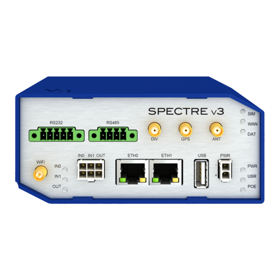
Connector for connection of USB devices to the router. Sup- Host ports devices with PL-2303 and FTDI USB/RS232 converters. 6-pin Connector for connection of the binary inputs and output Table 8: Front panel description Figure 24: SPECTRE v3 LTE front panel... -
Page 23: Status Indication
5. ROUTER DESIGN 5.8.1 Status indication About router status inform nine LED indicators on the front panel. Each ETH port has two additional LEDs that provide information about port status. Caption Color State Description Green Blinking Router is ready Starting of the router Fast blinking Updating firmware Yellow... -
Page 24: Power Connector Pwr
SPECTRE v3 LTE can be put into low power mode using a special command. Then it can be awakened for example by an activity on binary input or using an internal timer. -
Page 25: Antenna Connector Ant, Div, Gps And Wifi
5. ROUTER DESIGN 5.8.3 Antenna connector ANT, DIV, GPS and WiFi Main, diversity and GPS antennas are connected to the router using the SMA connector on the front panel. There is also available R-SMA antenna connector through which the additional antenna can be connected, if the router is equipped with WiFi module. -
Page 26: Sim Card Reader
5. ROUTER DESIGN 5.8.4 SIM card reader Two SIM card readers for 3 V and 1.8 V SIM cards are placed on the rear panel of the router. For getting the router to work is necessary to insert an activated SIM card with an unblocked PIN code. -
Page 27: Ethernet Port (Eth0 And Eth1)
5. ROUTER DESIGN Changing the microSD card: Use the flat end of a spudger, or your fingernail, to press the microSD card slightly deeper into its slot until you hear a click. After the click, release the card and it will pop out of its slot. Remove the microSD card and push any other microSD card into the slot until it clicks in place. -
Page 28: Usb Port
5. ROUTER DESIGN Ethernet cable plug into the RJ45 connector labeled as ETH0 or ETH1 (see figure below). Figure 31: Connection of ethernet cable The insulation strength is up to 1.5 kV. 5.8.7 USB Port Panel socket USB-A. Signal mark Description Data flow direction +5 V... -
Page 29: I/O Port
5. ROUTER DESIGN 5.8.8 I/O Port Panel socket 6-pin. Signal mark Description Binary input 0 Binary input 0 Binary input 1 Binary input 1 Binary output Binary output Table 14: Connection of I/O port Figure 33: I/O connector I/O user Interface is designed for processing of binary input and control (setting) binary output. -
Page 30: Binary Inputs Connection
5. ROUTER DESIGN Binary inputs connection with example: Figure 34: Binary inputs connection Binary output Binary output parameters: – 60 V AC / 300 mA – 60 V DC / 300 mA Current of binary output is limited by a resettable fuse (300 mA). Binary output connection with example: Figure 35: Binary output connection... -
Page 31: Reset
5. ROUTER DESIGN 5.8.9 Reset When PWR LED starts flashing on the front panel, it is possible to restore the default configuration of the router by pressing the RST button on the rear panel. After pressing this button the default configuration is restored and then router reboots (green LED will be on). For pressing the RST button could be used a narrow screwdriver. -
Page 32: Interfaces Description
5. ROUTER DESIGN 5.9 Interfaces description Besides the basic version of SPECTRE v3 router there are available versions with one of the following interfaces: RS232 interface RS232-RS485/422 interface SWITCH interface 5.9.1 RS232 interface This interface is physically connected on RJ45 connector. RS232 converter is protected against overload the bus. -
Page 33: Rs232 Connector
5. ROUTER DESIGN Figure 38: RS232 connector Example of a meter connection to router: Figure 39: Meter connection to router State indication of RS232 port: Description of indication Green LED Indicates Receive data Yellow LED Indicates Transmit data Table 18: State indication of RS232 port... -
Page 34: Rs232-Rs485/422 Interface
5. ROUTER DESIGN 5.9.2 RS232-RS485/422 interface These interfaces are physically connected on five-pin and four-pin terminal block connec- tors. The insulation strength is up to 2.5 kV. Attention, connectors are not isolated from each other! Figure 40: Version with RS232-RS485/422 interface Connection of RS232 connector: Signal Description... -
Page 35: Rs485/422 Connector
5. ROUTER DESIGN Connection of RS422 connector: Signal Description Direction RxD+ RS422 (+) Output RxD- RS422 (-) Output TxD+ RS422 (+) Input TxD- RS422 (-) Input Table 21: Connection of RS422 connector Figure 42: RS485/422 connector Selection of RS485 or RS422 can be performed using jumpers on the board. Positions where jumpers have to be mounted are shown on the port (see figure below). -
Page 36: Switch Interface
5. ROUTER DESIGN 5.9.3 SWITCH interface Three LAN ports of SWITCH interface intended for v3 routers (RJ-45 connectors for con- necting ethernet devices) act as it is a typical switch device. This means that the router with internal switch desk reads ethernet frames (a data packets on an ethernet link) from any port and transmits them on other ports of the switch board. -
Page 37: First Use
6. FIRST USE 6. First Use 6.1 Connecting the router before first use Before putting the router into operation it is necessary to connect all components which are required to run your applications. Don’t forget to insert SIM card. The router can not operate without connected antenna, SIM card and power supply. If the antenna is not connected, router can be demaged. -
Page 38: Start
6. FIRST USE 6.2 Start The router is put into operation when the power supply is connected to this router. By default, the router will automatically start to log on to the default APN. DHCP server will start to assign addresses for devices on the Ethernet port ETH0. Router behavior can be changed via the web interface. -
Page 39: Router Web Interface
6. FIRST USE After successfully entering login information user gains access to the router via his internet browser. Figure 48: Router web interface A detailed description of the router settings via the Web interface can be found in the document Configuration manual for v3 routers. -
Page 40: Technical Parameters
7. TECHNICAL PARAMETERS 7. Technical Parameters 7.1 Basic parameters SPECTRE v3 LTE Temperature range Operating -40 C to +75 C Storage -40 C to +85 C Cold start -35 C Data transfers via mobile network are available immediately -40 C Data transfers via mobile network are available approximately in five minutes after the start of... -
Page 41: Type Tests And Environmental Conditions
7. TECHNICAL PARAMETERS 7.2 Type tests and environmental conditions Phenomena Test Description Test levels EN 61000-4-2 Enclosure contact 6 kV (crit. A) Enclosure air 8 kV (crit. A) RF field AM IEC 61000-4-3 Enclosure 20 V/m (crit. A) modulated (80 – 2700 MHz) Fast transient EN 61000-4-4 Signal ports... -
Page 42: Technical Parameters Of Module
7. TECHNICAL PARAMETERS 7.3 Technical parameters of module 7.3.1 LTE module for EMEA LTE module for EMEA LTE parameters Bit rate 100 Mbps (DL) / 50 Mbps (UL) 3GPP rel. 8 standard Supported bandwidths: 5 MHz, 10 MHz, 20 MHz Supported frequencies: 800 / 900 / 1800 / 2100 / 2600 MHz HSPA+ parameters Bit rate 21,1 Mbps (DL) / 5,76 Mbps (UL) -
Page 43: Lte Module For Australia
7. TECHNICAL PARAMETERS Continued from previous page LTE module for NAM, AT&T operator GPRS/EDGE parameters Bit rate 237 kbps (DL) / 59,2 kbps (UL) GPRS multislot class 12, CS 1 to 4 EDGE multislot class 12, CS 1 to 4, MCS 1 až... -
Page 44: Lte Module Supports 450 Mhz
7. TECHNICAL PARAMETERS 7.3.4 LTE module supports 450 MHz LTE module supports 450 MHz LTE parameters Bit rate 100 Mbps (DL) / 50 Mbps (UL), UE CAT. 3 3GPP rel. 9 standard Supported bandwidths: 5 Mhz, 10 Mhz, 20 Mhz Supported frequencies: 450 / 800 / 1800 / 2600 MHz Rated Output Power: B3, B7, B20, 31 MIMO (Multi-Input Multi-Output) antenna support... -
Page 45: Technical Parameters Of Gps
7. TECHNICAL PARAMETERS 7.4 Technical parameters of GPS GPS is not available when the router is equipped with the LTE module 450 MHz! GPS specifications Antenna 50 Ohms – active Protocols NMEA 0183 v3.0 Frequency 1575.42 MHz Sensitivity Tracking: -161 dBm Acquisition (Assisted): -158 dBm Acquisition (Standalone): -145 dBm Acquisition time... -
Page 46: Technical Parameters Of I/O Port
7. TECHNICAL PARAMETERS 7.6 Technical parameters of I/O port Characteristics of inputs: logical 0 / 1 Voltage Current log. 0 max 0.4 mA log. 1 min 0.7 mA log. 1 type 12 V 2 mA log. 1 max 60 V 7 mA Table 31: Characteristics of inputs Binary output parameters:... -
Page 47: Recommended Literature
8. RECOMMENDED LITERATURE 8. Recommended Literature Conel: Start guide, Conel: Configuration manual for v3 routers. -
Page 48: Troubleshooting
9. TROUBLESHOOTING 9. Troubleshooting If you can not connect to the router from your PC, your network card may be configured the way it is not possible to connect to the router. Take one or more of the following steps to solve the problem: Select the communication rate 10 MB/s in the properties of your network card. - Page 49 9. TROUBLESHOOTING Ethernet connection fails or isn’t establishing. It is possible to turn auto negotiation off and set a rate and duplex manually on the Ethernet interface of the router. DynDNS doesn’t function. With private APN this is not functional. If the same IP address is recorded in your canonic name as dynamically assigned address, it means that the operator is using NAT or firewall.
-
Page 50: Customers Support
10. CUSTOMERS SUPPORT 10. Customers Support 10.1 Global Customer Support You can find up to date information about this product on our website: www.conel.com Upkeep-advices: The SIM-card must be handled carefully as with a credit card. Don’t bend, don’t scratch on this and do not expose to static electricity.
Need help?
Do you have a question about the SPECTRE v3 LTE and is the answer not in the manual?
Questions and answers