
Related Manuals for B+B SmartWorx UCR11 v2


Summary of Contents for B+B SmartWorx UCR11 v2
- Page 1 UCR11 v2 CDMA/UMTS router USER’S MANUAL LUCOM GmbH — Flößaustr. 22a — 90763 Fürth — Tel.: +49 911/ 957 606 00 — E-Mail: info@lucom.de — www.lucom.de...
- Page 2 USED SYMBOLS Used Symbols Danger – important notice, which may have an influence on the user’s safety or the function of the device. Attention – notice on possible problems, which can arise in specific cases. Information, notice – information, which contains useful advice or special interest. GPL License Source codes under GPL license are available free of charge by sending an email to: info@conel.cz.
-
Page 3: Table Of Contents
CONTENTS Contents 1 Safety Instruction 2 Product Disposal Instructions 3 Router description 4 Contents of package 5 Router design 5.1 Router versions ........5.2 Delivery identification . - Page 4 CONTENTS 7.3 Technical parameters of CDMA module ..... . 7.4 Technical parameters of processor ......7.5 Technical parameters I/O port .
- Page 5 LIST OF FIGURES List of Figures Contents of package ....... . . Front panel UCR11 v2F SL .
- Page 6 LIST OF TABLES List of Tables Router versions ........Delivery identification .
-
Page 7: Safety Instruction
1. SAFETY INSTRUCTION 1. Safety Instruction Please, observe the following instructions: The router must be used in compliance with all applicable international and national laws and in compliance with any special restrictions regulating the utilization of the router in prescribed applications and environments. To prevent possible injury to health and damage to appliances and to ensure that all the relevant provisions have been complied with, use only the original accessories. -
Page 8: Product Disposal Instructions
2. PRODUCT DISPOSAL INSTRUCTIONS 2. Product Disposal Instructions The WEEE (Waste Electrical and Electronic Equipment: 2002/96/EC) directive has been introduced to ensure that electrical/electronic products are recycled using the best available recovery techniques to minimize the impact on the environment. This product contains high quality materials and components which can be recycled. -
Page 9: Router Description
LAN networks, automatic teller machines (ATM) and other self-service terminals and machines. As a standard, UCR11 v2 router is equipped with one Ethernet 10/100, one USB Host port, one binary Input/output (I/O) port and two SIM cards. The wide range of interface op- tions of this router further expands an expansion PORT1 and PORT2 –... -
Page 10: Contents Of Package
4. CONTENTS OF PACKAGE 4. Contents of package Basic delivered set of router includes: router, power supply, crossover UTP cable, three external antennas, clip for the DIN rail, installation CD containing instructions, paper start guide. Figure 1: Contents of package The router can also be supplied as expansion accessories: Two expansion ports: RS232, RS485/422, MBUS, ETHERNET, CNT, SWITCH, WIFI, WMBUS or SDH. -
Page 11: Router Design
5. ROUTER DESIGN 5. Router design 5.1 Router versions UCR11 v2 router is supplied in the following versions: SIM1 SIM2 PORT1 PORT2 UCR11 v2F SL Metal Table 1: Router versions Figure 2: Front panel UCR11 v2F SL 5.2 Delivery identification... -
Page 12: Version Of Firmware Module
5. ROUTER DESIGN 5.3 Version of firmware module Each operator can have another CDMA network, so it is necessary to generate a special firmware for each operator. Version of the firmware is indicated by two-digit code in the name of the product. Operator Code Poland Orange... -
Page 13: Ordering Codes
Full version with Ethernet and RS232 port in metal cover: UCR11 v2F-01 ETH RS232 SL set. Router is standardly fitted with a diversity antenna for HSPA+. However, UCR11 v2 can be fitted with a diversity antenna for CDMA on customer’s request. In this case, it is necessary to write capital letter D behind two digits indicating the operator in ordering code. -
Page 14: Basic Dimensions Of Metal Box
5. ROUTER DESIGN 5.5 Basic dimensions of metal box Figure 4: Basic dimensions of metal box 5.6 Mechanical dimensions and mounting recommendations Mounting recommendations: possibility to be put on a work surface, DIN rail with clips CKD2 (ELPAC clip SL for metal version) are included. For the most of applications with a built-in router in a switch board it is possible to recognize two kinds of environments: no public and industry environment of low voltage with high interference,... -
Page 15: Space Around Antennas
5. ROUTER DESIGN before mounting a router on sheet-steel we recommend using an external antenna, Figure 5: Space around antennas For every cables we recommend to bind the bunch according to the following picture, we recommend for this use: – Length of the bunch (combination of power supply and data cables) can be max- imum 1,5 m. -
Page 16: Space In Front Of Connectors
5. ROUTER DESIGN Sufficient space must be left before individual connectors for handling of cables, Figure 7: Space in front of connectors For correct function of the router we recommend to use in the switch-board earth-bonding distribution frame for grounding of power supply of router, data cables and antenna. LUCOM GmbH —... -
Page 17: Default Position Of Din Holder
5. ROUTER DESIGN 5.7 Removing from the DIN rail Default position of CKD2 holder, which is used for mounting the router on a DIN rail, is shown in the following figure: Figure 8: Default position of DIN holder For removing from the DIN rail it is necessary to lightly push upward the router so that the top part of the CKD2 holder hitched to the DIN rail get out of this rail and then fold out the top part of the router away from the DIN rail. -
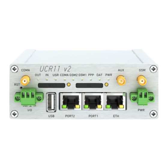
Page 18: Front Panel Ucr11 V2F Sl
5. ROUTER DESIGN 5.8 Description of the front panel On the front panel is located: Caption Connector Description 2-pin Connector for the power supply adapter. RJ45 Connector for connection into the local computer network. PORT1 RJ45 Connector for expansion port RS232, RS458/422, MBUS, ETHERNET, CNT or SWITCH. -
Page 19: Router Status Indication
5. ROUTER DESIGN 5.8.1 Status indication About router status inform nine led indicators on the front panel and on every port are two LED indicators, which inform about port status. Caption Color State Description Green Blinking Router is ready Starting of the router Fast blinking Updating firmware Blinking... -
Page 20: Power Connector
5. ROUTER DESIGN 5.8.2 Power connector PWR Panel socket 2-pin. Pin number Signal mark Description VCC(+) Positive pole of DC supply voltage (+9 to +36 V DC) GND(-) Negative pole of DC supply voltage Table 7: Connection of power connector Figure 11: Power connector Power supply for router is required between +9 V to +36 V DC supply. -
Page 21: External Antenna
5. ROUTER DESIGN 5.8.3 Antenna connector GSM, CDMA and AUX Both of main antennas are connected to the router using the SMA connector on the front panel. There is also available the third SMA antenna connector (AUX), through which diver- sity or additional antenna can be connected (in case of the WIFI expansion port is used this connector is reverse –... -
Page 22: Ejected Sim Holder
5. ROUTER DESIGN 5.8.4 SIM card reader The SIM card reader for 3 V and 1,8 V SIM cards is located on the front panel of the router. To initiate the router into operation it is necessary to insert an activated SIM card with un- blocked PIN in the reader. -
Page 23: Ethernet Connector
5. ROUTER DESIGN Figure 17: Ethernet connector ATTENTION! Port ETH is not POE (Power Over Ethernet) compatible! Ethernet cable plug into the RJ45 connector labeled as ETH (see figure below). Figure 18: Connection of ethernet cable Example of the ETH router connection: Figure 19: Example of router connection LUCOM GmbH —... -
Page 24: Port1 Cable Connection
5. ROUTER DESIGN 5.8.6 PORT1 The PORT1 is equipped on customer’s request with one of the offered expansion ports: RS232 MBUS RS485 RS422 SWITCH (together with PORT2) ETHERNET Description and examples of expansion ports connection can be found in user’s guide for corresponding expansion port. -
Page 25: Port2 Cable Connection
5. ROUTER DESIGN PORT2 cable plug into the RJ45 connector labeled as PORT1 (see figure below). Figure 21: PORT2 cable connection 5.8.8 USB Port Panel socket USB-A. Signal mark Description Data flow direction +5 V Positive pole of 5 V DC supply voltage USB data - USB data signal –... -
Page 26: Connection Plc To The Router
5. ROUTER DESIGN Example of connecting devices with serial interface to the USB: Figure 23: Connection PLC to the router Example of connecting of USB flash disk to the USB: Figure 24: Connection flash memory to the router 5.8.9 I/O Port Panel socket 3pin. -
Page 27: Connection Of I/O Cable
5. ROUTER DESIGN Maximum load binary output is 30 V / 100 mA. The constant current supplied by the binary input is 3 mA. Connector I/O cable connect into the I/O connector on the router head and tighten locking screws (see figure below). Figure 26: Connection of I/O cable Circuit example of a binary input or output equipment with router: Figure 27: Connection of input and output to the router... -
Page 28: Router Reset
5. ROUTER DESIGN 5.8.10 Reset It is important to distinguish between reset and reboot the router. Action Router behavior Invoking events Reboot Turn off and then turn on router Disconnect and connect the power, Press the Reboot button in the web configuration Reset Restore default configuration and reboot... -
Page 29: First Use
6. FIRST USE 6. First use 6.1 Connecting the router before first use Before you give up the router, it is necessary to connect all components needed for the operation of your applications and the SIM card must be inserted (see figure below). The router can not operate without connected antenna, SIM card and power supply. - Page 30 6. FIRST USE 6.2 Start The router is set up connecting the power supply to the router. In the default setting the router starts to login automatically to the preset APN. Device on the Ethernet port DHCP server will assign addresses. The behavior of the router can be modified by means of the web or Telnet interface, which is described in the configuration manual.
-
Page 31: Technical Parameters
7. TECHNICAL PARAMETERS 7. Technical parameters 7.1 Technical parameters of router UCR11 v2 Complies with standards EN 301 511, v9.0.2, EN 301 908-1 & -2: v3.2.1, ETSI EN 301 489-1 V1.8.1, EN 60950-1:06 ed.2 + A11:09 + A1:10 Temperature range... -
Page 32: Technical Parameters Of Cdma Module
7. TECHNICAL PARAMETERS Continued from previous page UMTS modul GPRS/EDGE parameters Bit rate 237 kbps (DL) / 59,2 kbps (UL) GPRS multislot class 10, CS 1 to 4 EDGE multislot class 12, CS 1 to 4, MCS 1 to 9 Power classes EGSM 900: Class 4 (33 dBm) GSM 1800/1900: Class 1 (30 dBm) -
Page 33: Technical Parameters I/O Port
7. TECHNICAL PARAMETERS 7.5 Technical parameters I/O port 32b ARM mikroprocesor Input/Output Binary input Reed contact with trigger level 1,3 up to 1,4 V Binary output 120 mA / max. 30 V Table 16: Technical parameters I/O port 7.6 Technical parameters of expansion port Technical parameters of the expansion ports are specified in separate manuals for expan- sion ports. -
Page 34: Recommended Literature
8. RECOMMENDED LITERATURE 8. Recommended literature Conel: Start guide, Conel: Configuration manual, Conel: User’s manual – Expansion port RS232, Conel: User’s manual – Expansion port RS485/RS422, Conel: User’s manual – Expansion port MBUS, Conel: User’s manual – Expansion port CNT, Conel: User’s manual –... -
Page 35: Possible Problems
9. POSSIBLE PROBLEMS 9. Possible problems Some network cards are able to be set in situation, when it is not possible to connect the router. It is possible to solve this problem in the following steps: hand by selection communication rates 10 MB/s in property network cards, connect router over switch, start computer only after finalizing the start of the router. -
Page 36: Faq
10. FAQ 10. FAQ I can’t get from internet on equipment, which is connected to router and I have NAT en- abled. The device’s gateway has to be configured as the router. Router resets itself, connection on Ethernet fails. It is necessary to use an antenna, which will be situated far from power supply. I don’t get on web server at NAT. - Page 37 10. FAQ The operator doesn’t give out address DNS servers and without DNS server’s it is impossible to connect to server dyndns.org. In log system will be this message: – DynDNS daemon started – Error resolving hostname: no such file or directory –...
-
Page 38: Customers Support
11. CUSTOMERS SUPPORT 11. Customers Support You can find current information about this product on our website: www.conel.com Upkeep-advices: The SIM-card must be handled carefully as with a credit card. Don’t bend, don’t scratch on this and do not expose to static electricity. During cleaning of the router do not use aggressive chemicals, solvents and abrasive cleaners! Conel Company hereby declares that the router narrated in this user’s guide fits all basic de-...
Need help?
Do you have a question about the UCR11 v2 and is the answer not in the manual?
Questions and answers