
Related Manuals for IBASE Technology MI991AF


Summary of Contents for IBASE Technology MI991AF
- Page 1 MI991 Intel Generation Core ® C236/Q170/H110 PCH Mini ITX Motherboard USER’S MANUAL Version 1.1...
- Page 2 Acknowledgments AMI is a registered trademark of American Megatrends Inc. PS/2 is a trademark of International Business Machines Corporation. ® Intel and Intel Generation Core DC/QC Processor are registered trademarks of Intel Corporation. Microsoft Windows is a registered trademark of Microsoft Corporation.
-
Page 3: Table Of Contents
Table of Contents Introduction ............1 Product Description............. 1 Checklist ................2 MI991 Specifications ............3 Board Dimensions ............... 5 Installations ............6 Installing the CPU ............... 7 Installing the Memory ............8 Setting the Jumpers ............. 9 Connectors on MI991 ............13 BIOS Setup ............ - Page 4 This page is intentionally left blank. MI991 User’s Manual...
-
Page 5: Introduction
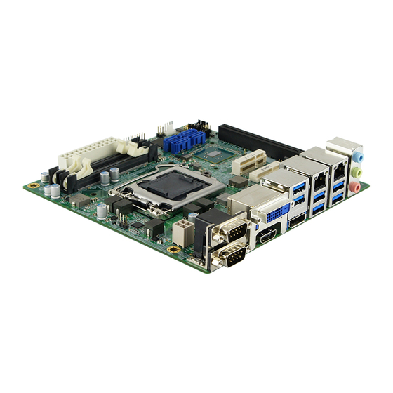
Intel’s latest cutting-edge technology. Measuring 170mm x 170mm, the MI991 offers fast 6Gbps SATA support (4 ports), USB3.0 (6 ports) and interfaces for DVI-D, HDMI and DP displays. MI991AF-C236 and MI991AF features ® Intel Active Management Technology 11.0. -
Page 6: Checklist
INTRODUCTION Checklist Your MI991 package should include the items listed below. • The MI991 Mini ITX motherboard • This User’s Manual • 1 DVD containing chipset drivers and flash memory utility • Serial ATA cable • USB cable • COM port cable •... -
Page 7: Mi991 Specifications
USB 3.0 host controller [PCH Integrated], support 6 ports - 4 ports via rear panel I/O [USB3 port #1~#4] - Extra 2 ports via rear I/O panel [USB3 port #5~#6] (**MI991AF only**) USB 2.0 host controller [PCH Integrated], support 6 ports... - Page 8 CPU Fan x 1(PWM type, 4-pin) + SYS FAN x 1(PWM type, 4-pin) 4 in & 4 out Digital IO ® Intel C236/ Q170 PCH built-in (MI991AF only) IAMT 11.0 Infineon SLB9660 [C01Z9660TT1207000P] for MI991AF series TPM 1.2 Co-lay with ATMEL AT97SC3204-X4A14-10 [C01Z97SC3204X4000P] **Meet FIPS 140-2 certification** - PCI-Express (16x) x1 [Gen 3.0 PEG]...
-
Page 9: Board Dimensions
INTRODUCTION Board Dimensions MI991 User’s Manual... -
Page 10: Installations
INSTALLATIONS Installations This section provides information on how to use the jumpers and connectors on the MI991 in order to set up a workable system. The topics covered are: Installing the CPU .................. 7 Installing the Memory ................8 Setting the Jumpers ................9 Connectors on MI991 ................ -
Page 11: Installing The Cpu
INSTALLATIONS Installing the CPU The MI991 board supports an LGA1151 Socket (shown below) for Intel Generation Core processors. To install the CPU, unlock first the socket by pressing the lever sideways, then lift it up to a 90-degree. Then, position the CPU above the socket such that the CPU corner aligns with the gold triangle matching the socket corner with a small triangle. -
Page 12: Installing The Memory
INSTALLATIONS Installing the Memory The MI991 board supports two DDR4 memory socket for a maximum total memory of 32GB in DDR4 SO-DIMM memory type. Installing and Removing Memory Modules To install the DDR4 modules, locate the memory slot on the board and perform the following steps: 1. -
Page 13: Setting The Jumpers
Jumper Locations on MI991 ..............10 JBAT2: Clear RTC Contents .............. 11 JP1, JP2: PCI-E x16 Mode Selection ..........12 Note: MI991AF-C236 and MI991AF used only ........12 JP3: Flash Descriptor Security Override (Factory use only) ....12 MI991 User’s Manual... - Page 14 INSTALLATIONS Jumper Locations on MI991 Jumpers on MI991 ................Page JBAT1: Clear CMOS Contents ............11 JBAT2: Clear RTC Contents ............... 11 JP1, JP2: PCI-E x16 Mode Selection ........... 11 JP3: Flash Descriptor Security Override (Factory use only) ....12 MI991 User’s Manual...
- Page 15 INSTALLATIONS JBAT1: Clear CMOS Contents (E-CALL 0125-01-203-030) JBAT1 Setting Function Pin 1-2 Normal Short/Closed Pin 2-3 Clear CMOS Short/Closed JBAT2: Clear RTC Contents (0195-01-200-020) Flash Descriptor JBAT2 Security Override Normal Open (Default) Close Clear RTC MI991 User’s Manual...
- Page 16 Function JP1/Open 1 x16 (Default) JP2/Open JP1/Open 2 x8 JP2/Short JP1/Short 1 x8, 2 x4 JP2/Short Note: MI991AF-C236 and MI991AF used only JP3: Flash Descriptor Security Override (Factory use only) (0195-01-200-020) Flash Descriptor Security Override Disabled Open (Default) Close Enabled...
-
Page 17: Connectors On Mi991
INSTALLATIONS Connectors on MI991 Connector Locations on MI991 ............14 CN1: COM1 and COM2 Serial Ports ..........15 CN2, CN3: DVI-D and HDMI Connector ........... 15 CN4, CN5: Display Port + USB3.0 0/1 Connector ......15 CN6: Gigabit LAN (Intel I219LM/I219V) + USB3.0 2/3 ....15 CN7, CN8, CN10, CN11: SATA Connectors ........ -
Page 18: Connector Locations On Mi991
INSTALLATIONS Connector Locations on MI991 MI991 User’s Manual... -
Page 19: Cn1: Com1 And Com2 Serial Ports
INSTALLATIONS CN1: COM1 and COM2 Serial Ports (40909AANSABR) Pin # Signal Name RS-232 R2-422 RS-485 DATA- DATA+ Ground Ground Ground Note: COM2 Support RS-232 only. CN2, CN3: DVI-D and HDMI Connector CN4, CN5: Display Port + USB3.0 0/1 Connector CN6: Gigabit LAN (Intel I219LM/I219V) + USB3.0 2/3 CN7, CN8, CN10, CN11: SATA Connectors CN9: Gigabit LAN (Intel I211AT) + USB3.0 4/5 CN12: HD Audio Connector... -
Page 20: J2: Atx 12V Power Connector
INSTALLATIONS J2: ATX 12V Power Connector (HAOGUO ATX4PT-NY46) This connector supplies the CPU operating voltage. Pin # Signal Name Ground Ground +12V +12V J3, J4: DDR4 SO-DIMM Connector (LOTES DDR0075-P001C) MI991 User’s Manual... -
Page 21: J5: Atx Power Supply Connector
INSTALLATIONS J5: ATX Power Supply Connector (HAOGUO 01-0018-03) Signal Name Pin # Pin # Signal Name 3.3V 3.3V -12V 3.3V Ground Ground PS-ON Ground Ground Ground Ground Ground Power good 5VSB +12V +12V Ground +3.3V MI991 User’s Manual... -
Page 22: J7: Digital I/O Connector
INSTALLATIONS J7: Digital I/O Connector (E-CALL 0126-01-203-100) Signal Name Pin # Pin # Signal Name OUT3 OUT1 OUT2 OUT0 J9: Mini PCI-E Connector (Foxconn AS0B226-S56Q-7H) MI991 User’s Manual... -
Page 23: J10: Mini Pci-E Connector
INSTALLATIONS J10: Mini PCI-E Connector (Supports mSATA Function) (Foxconn AS0B226-S99Q-7H) J11: ACPI Status LED (E-CALL 0126-01-203-040) Pin # Signal Name +3VDUAL +VCC3 MI991 User’s Manual... -
Page 24: J12: Spi Flash Connector (Factory Use Only)
INSTALLATIONS J12: SPI Flash Connector (Factory use only) (E-CALL 0196-01-2001009) J13: Debug 80 Port Connector (Factory use only) (E-CALL 0196-01-2001009) J14: Battery Connector (世均1252-WS2-02-LF) Pin # Signal Name Battery+ MI991 User’s Manual... -
Page 25: J15: Usb2.0 Connectors
INSTALLATIONS J15: USB2.0 Connectors (HAOGUO DF11-8S-PA66H) Signal Name Pin # Pin # Signal Name Ground Ground J16: Audio Pin Header for Chassis Front Panel (E-CALL 0126-01-2821009) Signal Name Pin # Pin # Signal Name MIC IN_L Ground MIC IN_R LINE_R Sense Ground Sense LINE_L... -
Page 26: J17, J18: Com3/4 Rs232 Serial Ports
INSTALLATIONS J17, J18: COM3/4 RS232 Serial Ports (HAOGUO DF11-10S-PA66H) Signal Name Pin # Pin # Signal Name DCD# DSR# RTS# SOUT CTS# DTR# J19: Front Panel Function Connector (0196-01-200-080) Signal Name Pin # Pin # Signal Name Ground PWR_SW PWR_LED+ PWR_LED-(GND) HDD_LED+ HDD_LED-... -
Page 27: Cpu_Fan1: Cpu Fan Power Connector
INSTALLATIONS CPU_FAN1: CPU Fan Power Connector (HF27040-M1) Pin # Signal Name Ground +12V Rotation detection Control SYS_FAN1: System Fan1 Power Connector (HF27040-M1) Pin # Signal Name Ground +12V Rotation detection Control MI991 User’s Manual... -
Page 28: Pcie1: Pci-E X16 Slot
INSTALLATIONS PCIE1: PCI-E X16 Slot (2EG08211-D2D-DF) MI991 User’s Manual... -
Page 29: Bios Setup
BIOS SETUP BIOS Setup This chapter describes the different settings available in the AMI BIOS that comes with the board. The topics covered in this chapter are as follows: BIOS Introduction ..................26 BIOS Setup ....................26 ............錯誤! 尚未定義書籤。 Advanced Settings ............ - Page 30 BIOS SETUP BIOS Introduction The BIOS (Basic Input/Output System) installed in your computer system’s ROM supports Intel processors. The BIOS provides critical low-level support for a standard device such as disk drives, serial ports and parallel ports. It also password protection as well as special support for detailed fine-tuning of the chipset controlling the entire system.
- Page 31 BIOS SETUP Main Settings Aptio Setup Utility – Copyright © 2011 American Megatrends, Inc. Main Advanced Chipset Security Boot Save & Exit Choose the system default language Total Memory 4096 MB → ← Select Screen Memory Frequency 2133 MHz ↑↓ Select Item Enter: Select Change Field System Date...
- Page 32 BIOS SETUP Advanced Settings This section allows you to configure and improve your system and allows you to set up some system features according to your preference. Aptio Setup Utility Advanced Main Chipset Security Boot Save & Exit ► CPU Configuration ►...
- Page 33 BIOS SETUP Enable/Disable AES (Advanced Encryption Standard. Power & Performance Aptio Setup Utility Advanced Main Chipset Security Boot Save & Exit → ← Select Screen Power & Performance ↑↓ Select Item ► CPU - Power Management Control Enter: Select Change Field F1: General Help F2: Previous Values F3: Optimized Default...
- Page 34 F2: Previous Values F3: Optimized Default F4: Save ESC: Exit Security Device Support This configuration is supported only with MI991AF-C236 and MI991AF. Enables or Disables TPM support. O.S. will not show TPM. Reset of platform is required. MI991 User’s Manual...
- Page 35 BIOS SETUP ACPI Settings Aptio Setup Utility Advanced Main Chipset Security Boot Save & Exit → ← ACPI Settings Select Screen ↑↓ Select Item Enable Hibernation Enabled Enter: Select Change Field ACPI Sleep State S3 (Suspend to R…) F1: General Help F2: Previous Values F3: Optimized Default F4: Save...
- Page 36 BIOS SETUP iSmart Controller Aptio Setup Utility Advanced Main Chipset Security Boot Save & Exit iSmart Controller → ← Select Screen Power-On after Power failure Disable ↑↓ Select Item Temperature Guardian Disable Enter: Select Schedule Slot 1 None Change Field F1: General Help Schedule Slot 2 None...
- Page 37 BIOS SETUP F81846 Super IO Configuration Aptio Setup Utility Advanced Main Chipset Security Boot Save & Exit F81846 Super IO Configuration → ← Select Screen Super IO Chip F81866 ↑↓ Select Item Enter: Select Standby Power on S5(Eup) All Enable Change Field F1: General Help ►...
- Page 38 BIOS SETUP Hardware Monitor Aptio Setup Utility Advanced Main Chipset Security Boot Save & Exit PC Health Status CPU smart fan control Disabled System smart fan control Disabled CPU temperature +33 C System temperature +34 C CPU FAN Speed 2170 RPM SYS FAN Speed →...
- Page 39 BIOS SETUP CSM Configuration Aptio Setup Utility Advanced Main Chipset Security Boot Save & Exit Option ROM execution → ← Select Screen Network Do not launch ↑↓ Select Item Enter: Select Change Field F1: General Help F2: Previous Values F3: Optimized Default F4: Save ESC: Exit Network...
- Page 40 BIOS SETUP USB Configuration Aptio Setup Utility – Copyright © 2012 American Megatrends, Inc. Advanced Main Chipset Boot Security Save & Exit USB Configuration USB Module Version USB Controllers: 1 XHCI USB Devices: 1 Keyboard → ← Select Screen Legacy USB Support Enabled ↑↓...
- Page 41 BIOS SETUP Device power-up delay Maximum time the device will take before it properly reports itself to the Host Controller. ‘Auto’ uses default value: for a Root port it is 100ms, for a Hub port the delay is taken from Hub descriptor. EHCI Hand-off Enabled/Disabled.
- Page 42 BIOS SETUP Chipset Settings This section allows you to configure and improve your system and allows you to set up some system features according to your preference. Aptio Setup Utility Chipset Main Advanced Security Boot Save & Exit ► System Agent (SA) Configuration →...
- Page 43 BIOS SETUP Graphics Configuration Aptio Setup Utility Chipset Main Advanced Security Boot Save & Exit Graphics Configuration Skip Scanning of External Gfx Card Disabled → ← Primary Display Auto Select Screen Select PCIE Card Auto ↑↓ Select Item ► External Gfx Card Primary Display Enter: Select Configuration Change Field...
- Page 44 BIOS SETUP External Gfx Card Primary Display Configuration Aptio Setup Utility Chipset Main Advanced Security Boot Save & Exit External Gfx Card Primary Display Configuration Primary PEG Auto Primary PCIE Auto → ← Select Screen ↑↓ Select Item Enter: Select Change Field F1: General Help F2: Previous Values...
- Page 45 BIOS SETUP PCH-IO Configuration This section allows you to configure the North Bridge Chipset. Aptio Setup Utility Chipset Main Advanced Security Boot Save & Exit PCH-IO Configuration → ← Select Screen ► SATA And RST Configuration ↑↓ Select Item PCH LAN Controller Enabled Enter: Select Change Field...
- Page 46 BIOS SETUP SATA And RST Configuration SATA Devices Configuration. Aptio Setup Utility – Copyright © 2012 American Megatrends, Inc. Advanced Main Chipset Security Boot Save & Exit SATA Controller(s) Enabled SATA Mode Selection AHCI SATA Port0 Empty Software Preserve Unknown Hot Plug Disabled SATA Port1...
- Page 47 BIOS SETUP Security Settings This section allows you to configure and improve your system and allows you to set up some system features according to your preference. Aptio Setup Utility Security Main Advanced Chipset Boot Save & Exit Password Description If ONLY the Administrator’s password is set, then this only limit access to Setup and is only asked for when entering Setup.
- Page 48 BIOS SETUP Boot Settings This section allows you to configure the boot settings. Aptio Setup Utility Boot Main Advanced Chipset Security Save & Exit Boot Configuration Setup Prompt Timeout Bootup NumLock State Quiet Boot Disabled Fast Boot Disabled Boot mode Select LEGACY FIXED BOOT ORDER Priorities Boot Option #1...
- Page 49 BIOS SETUP Save & Exit Settings Aptio Setup Utility Save & Exit Main Advanced Chipset Security Boot Save Options Save Changes and Exit Discard Changes and Exit Save Changes and Reset Discard Changes and Reset → ← Select Screen Save Changes ↑↓...
- Page 50 BIOS SETUP This page is intentionally left blank. MI991 User’s Manual...
-
Page 51: Drivers Installation
DRIVERS INSTALLATION Drivers Installation This section describes the installation procedures for software and drivers. The software and drivers are included with the motherboard. If you find the items missing, please contact the vendor where you made the purchase. The contents of this section include the following: Intel Chipset Software Installation Utility ........... -
Page 52: Intel Chipset Software Installation Utility
DRIVER INSTALLATION Intel Chipset Software Installation Utility The Intel Chipset Drivers should be installed first before the software drivers to enable Plug & Play INF support for Intel chipset components. Follow the instructions below to complete the installation. 1. Insert the DVD that comes with the board. Click Intel and then Intel(R) Skylake Chipset Drivers. - Page 53 DRIVERS INSTALLATION 3. When the Welcome screen to the Intel® Chipset Device Software appears, click Next to continue. 4. Click Yes to accept the software license agreement and proceed with the installation process. 5. On the Readme File Information screen, click Install to continue the installation.
-
Page 54: Vga Drivers Installation
DRIVER INSTALLATION VGA Drivers Installation 1. Insert the DVD that comes with the board. Click Intel and then Intel(R) Skylake Chipset Drivers. 2. Click Intel(R) HD Graphics Driver. MI991 User’s Manual... - Page 55 DRIVERS INSTALLATION 3. When the Welcome screen appears, click Next to continue. 4. Click Yes to to agree with the license agreement and continue the installation. MI991 User’s Manual...
- Page 56 DRIVER INSTALLATION 5. On the screen shown below, click Install to continue. 6. Setup complete. Click Finish to restart the computer and for changes to take effect. MI991 User’s Manual...
-
Page 57: Realtek Hd Audio Driver Installation
DRIVERS INSTALLATION Realtek HD Audio Driver Installation 1. Insert the DVD that comes with the board. Click Intel and then Intel(R) Skylake Chipset Drivers. 2. Click Realtek High Definition Audio Driver. MI991 User’s Manual... - Page 58 DRIVER INSTALLATION 3. On the Welcome to the InstallShield Wizard screen, click Next to proceed with and complete the installation process. 4. The InstallShield Wizard Complete. Click Finish to restart the computer and for changes to take effect. MI991 User’s Manual...
-
Page 59: Lan Drivers Installation
DRIVERS INSTALLATION LAN Drivers Installation 1. Insert the DVD that comes with the board. Click Intel and then Intel(R) Skylake Chipset Drivers. 2. Click Intel(R) PRO LAN Network Driver. MI991 User’s Manual... - Page 60 DRIVER INSTALLATION 3. Click Install Drivers and Software. 4. When the Welcome screen appears, click Next. MI991 User’s Manual...
- Page 61 DRIVERS INSTALLATION 5. Click Next to to agree with the license agreement. 6. Click the checkbox for Drivers in the Setup Options screen to select it and click Next to continue. 7. The wizard is ready to begin installation. Click Install to begin the installation.
-
Page 62: Intel® Management Engine Interface
DRIVER INSTALLATION Intel® Management Engine Interface 1. Insert the DVD that comes with the board. Click Intel and then Intel(R) Skylake Chipset Drivers. MI991 User’s Manual... - Page 63 DRIVERS INSTALLATION 2. When the Welcome screen to the InstallShield Wizard for Intel® Management Engine Components, click the checkbox for Install Intel® Control Center & click Next. 3. Click Next to to agree with the license agreement. 4. When the Setup Progress screen appears, click Next. Then, click Finish when the setup progress has been successfully installed.
-
Page 64: Intel® Usb 3.0 Drivers
DRIVER INSTALLATION Intel® USB 3.0 Drivers 1. Insert the DVD that comes with the board. Click Intel and then Intel(R) Skylake Chipset Drivers. 2. Click Intel(R) USB 3.0 Drivers. MI991 User’s Manual... - Page 65 DRIVERS INSTALLATION 3. When the Welcome screen to the InstallShield Wizard for Intel® USB 3.0 eXtensible Host Controller Driver, click Next. 4. Click Next to to agree with the license agreement and continue the installation. MI991 User’s Manual...
- Page 66 DRIVER INSTALLATION 5. On the Readme File Information screen, click Next to continue the installation of the Intel® USB 3.0 eXtensible Host Controller Driver. 6. Setup complete. Click Finish to restart the computer and for changes to take effect. MI991 User’s Manual...
-
Page 67: Appendix
APPENDIX Appendix A. I/O Port Address Map Each peripheral device in the system is assigned a set of I/O port addresses which also becomes the identity of the device. The following table lists the I/O port addresses used. Address Device Description 0000h-0CF7h PCI Express Root Complex 0040h-0043h... -
Page 68: Interrupt Request Lines (Irq)
APPENDIX B. Interrupt Request Lines (IRQ) Peripheral devices use interrupt request lines to notify CPU for the service required. The following table shows the IRQ used by the devices on board. Level Function IRQ0 System Timer IRQ3 Serial Port #2 IRQ4 Serial Port #1 IRQ5... -
Page 69: Watchdog Timer Configuration
APPENDIX C. Watchdog Timer Configuration The WDT is used to generate a variety of output signals after a user programmable count. The WDT is suitable for use in the prevention of system lock-up, such as when software becomes trapped in a deadlock. Under these sorts of circumstances, the timer will count to zero and the selected outputs will be driven. - Page 70 APPENDIX //--------------------------------------------------------------------------- void EnableWDT(int interval) unsigned char bBuf; bBuf = Get_F81866_Reg(0x2B); bBuf &= (~0x20); Set_F81866_Reg(0x2B, bBuf); //Enable WDTO Set_F81866_LD(0x07); //switch to logic device 7 Set_F81866_Reg(0x30, 0x01); //enable timer bBuf = Get_F81866_Reg(0xF5); bBuf &= (~0x0F); bBuf |= 0x52; Set_F81866_Reg(0xF5, bBuf); //count mode is second Set_F81866_Reg(0xF6, interval);...
- Page 71 APPENDIX //--------------------------------------------------------------------------- // THIS CODE AND INFORMATION IS PROVIDED "AS IS" WITHOUT WARRANTY OF ANY // KIND, EITHER EXPRESSED OR IMPLIED, INCLUDING BUT NOT LIMITED TO THE // IMPLIED WARRANTIES OF MERCHANTABILITY AND/OR FITNESS FOR A PARTICULAR // PURPOSE. //--------------------------------------------------------------------------- #include "F81866.H"...
- Page 72 APPENDIX unsigned char Get_F81866_Reg(unsigned char REG) unsigned char Result; Unlock_F81866(); outportb(F81866_INDEX_PORT, REG); Result = inportb(F81866_DATA_PORT); Lock_F81866(); return Result; //--------------------------------------------------------------------------- //--------------------------------------------------------------------------- // THIS CODE AND INFORMATION IS PROVIDED "AS IS" WITHOUT WARRANTY OF ANY // KIND, EITHER EXPRESSED OR IMPLIED, INCLUDING BUT NOT LIMITED TO THE // IMPLIED WARRANTIES OF MERCHANTABILITY AND/OR FITNESS FOR A PARTICULAR // PURPOSE.
Need help?
Do you have a question about the MI991AF and is the answer not in the manual?
Questions and answers