
Related Manuals for IBASE Technology MI999


Summary of Contents for IBASE Technology MI999
- Page 1 MI999 ® ® Intel Gen. Xeon ® ® Core™ / Pentium / Celeron Mini-ITX Motherboard User’s Manual Version 1.0...
- Page 2 No part of this publication may be reproduced, copied, stored in a retrieval system, translated into any language or transmitted in any form or by any means, electronic, mechanical, photocopying, or otherwise, without the prior written consent of IBASE Technology, Inc. (hereinafter referred to as “IBASE”). Disclaimer IBASE reserves the right to make changes and improvements to the products described in this document without prior notice.
- Page 3 0.1% by weight (1000 ppm) except for cadmium, limited to 0.01% by weight (100 ppm). • Lead (Pb) • Mercury (Hg) • Cadmium (Cd) • Hexavalent chromium (Cr6+) • Polybrominated biphenyls (PBB) • Polybrominated diphenyl ether (PBDE) MI999 User’s Manual...
- Page 4 Danger of explosion if the internal lithium-ion battery is replaced by an incorrect type. Replace only with the same or equivalent type recommended by the manufacturer. Dispose of used batteries according to the manufacturer’s instructions or recycle them at a local recycling facility or battery collection point. MI999 User’s Manual...
- Page 5 Software in use (such as OS and application software, including the version numbers) If repair service is required, you can download the RMA form at http://www.ibase.com.tw/english/Supports/RMAService/. Fill out the form and contact your distributor or sales representative. MI999 User’s Manual...
-
Page 6: Table Of Contents
2.1.1 Installing the CPU ..............12 2.1.2 Installing the Memory ............12 Setting the Jumpers ................13 Jumper & Connector Locations on MI999 .......... 14 Jumpers Quick Reference ..............15 2.4.1 eDP Panel Power Selection (JP5) ........15 2.4.2 Clear CMOS Data (JP9) ............16 2.4.3... - Page 7 Advanced Settings ................44 Chipset Settings ................56 Security Settings ................59 Boot Settings ..................61 Save & Exit Settings ................62 Appendix ..................63 I/O Port Address Map ................64 Interrupt Request Lines (IRQ) ............66 Watchdog Timer Configuration ............67 On-Board Connector Types ...............71 MI999 User’s Manual...
-
Page 9: Chapter 1 General Information
Chapter 1 General Information The information provided in this chapter includes: • Features • Packing List • Specifications • Block Diagram • Board View • Board Dimensions... -
Page 10: Introduction
Introduction ® ® MI999 is a Mini-ITX motherboard based on 10 Gen. Intel Xeon W/ Core™ ® ® / Pentium / Celeron processor. Designed for a broad range of markets, including industrial control & automation, digital signage, thin client, gaming, and transportation applications, it offers high-definition visual experience with high performance graphics processing. -
Page 11: Packing List
COM Port Cable (PK1-20BK) • Disk (including chipset drivers) • This User’s Manual Optional Accessories IBASE provides optional accessories as follows. Please contact us or your dealer if you need any. • Audio Cable (Audio-34) • USB Cable (USB-29) MI999 User’s Manual... -
Page 12: Specifications
AMI BIOS BIOS iSMART RAID 0/ 1/ 5/ 10 RAID For MI999AF(E)-W & MI999AF(E)-Q w/ iAMT Xeon-E / Core i7/ i5 DT CPU vPro EuP /Erp Dimensions 170mm x 170mm RoHS 2.0 CE (EN55032:2012); FCC Class B Certification MI999 User’s Manual... - Page 13 • Operating: 0 ~ 60 °C (32 ~ 140 °F) Temperature • Storage: -20 ~ 80 °C (-4 ~ 176 °F) Relative 0 ~ 95 %, non-condensing at 60 °C Humidity All specifications are subject to change without prior notice. MI999 User’s Manual...
-
Page 14: Block Diagram
Block Diagram MI999 User’s Manual... -
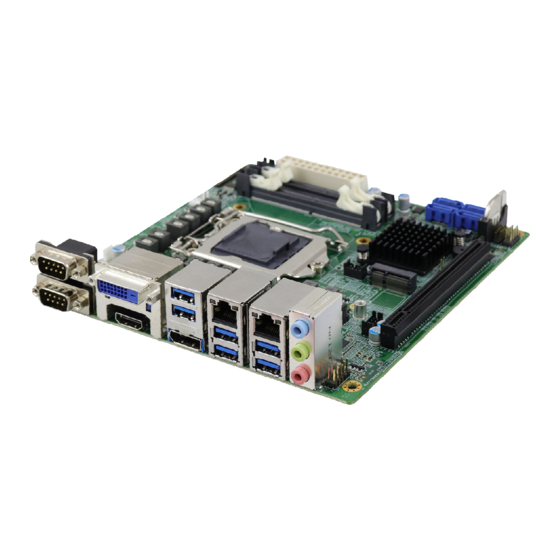
Page 15: Board View
General Information Board View Top View *The photos are for reference only. Some minor components may differ. MI999 User’s Manual... - Page 16 Bottom View I/O View Name Name COM1 Port Audio Line-In COM2 Port Audio Line-Out DVI-D Port Microphone-In USB 3.0 Ports DisplayPort GbE LAN Ports HDMI Port MI999 User’s Manual...
-
Page 17: Dimensions
General Information Dimensions MI999 User’s Manual... - Page 18 This page is intentionally left blank. MI999 User’s Manual...
-
Page 19: Chapter 2 Hardware Configuration
Chapter 2 Hardware Configuration This section provides information on jumper settings and connectors on the board in order to set up a workable system. On top of that, you will also need to install crucial pieces such as the CPU and the memory before using the product. The topics covered are: •... -
Page 20: Installations
Gently push the module in an upright position unitl the ejector tabs of the memory slot close to hold the module in place when the module touches the bottom of the slot. To remove the module, press the ejector tabs outwards with your fintertips to eject the module. MI999 User’s Manual... -
Page 21: Setting The Jumpers
1 2 3 When two pins of a jumper are encased in a jumper cap, this jumper is closed, i.e. turned On. When a jumper cap is removed from two jumper pins, this jumper is open, i.e. turned Off. MI999 User’s Manual... -
Page 22: Jumper & Connector Locations On Mi999
Jumper & Connector Locations on MI999 MI999 User’s Manual... -
Page 23: Jumpers Quick Reference
LVDS Panel Brightness Selection LVDS Panel Power Selection PCIe Bifurcation Selection JP1, JP2 Note: The board drawings below include all the connectors of different models. 2.4.1 eDP Panel Power Selection (JP5) Function Pin closed Illustration 3.3V (default) MI999 User’s Manual... -
Page 24: Clear Cmos Data (Jp9)
2.4.2 Clear CMOS Data (JP9) Function Pin closed Illustration Normal (default) Clear CMOS MI999 User’s Manual... -
Page 25: Clear Me Register (Jp8)
Hardware Configuration 2.4.3 Clear ME Register (JP8) Function Pin closed Illustration Normal (default) Clear ME MI999 User’s Manual... -
Page 26: Atx & At Power Mode Selection (Jp3)
2.4.4 ATX & AT Power Mode Selection (JP3) Function Pin closed Illustration ATX Mode (default) AT Mode MI999 User’s Manual... -
Page 27: Lvds Power Brightness Selection (Jp4)
Hardware Configuration 2.4.5 LVDS Power Brightness Selection (JP4) Function Pin closed Illustration 3.3V (default) MI999 User’s Manual... -
Page 28: Lvds Panel Power Selection (Jp6)
2.4.6 LVDS Panel Power Selection (JP6) Function Pin closed Illustration 3.3V (default) MI999 User’s Manual... -
Page 29: Pcie (X16) Bifurcation Selection (Jp1 & Jp2)
PCIe (x16) Bifurcation Selection (JP1 & JP2) Function Pin closed Illustration JP2: Open 1 x PCIe (x16) (default) JP1: Open JP2: Open 2 x PCIe (x8) JP1: Close JP2: Close 1 x PCIe (x8) 2 x PCIe (x4) JP1: Close MI999 User’s Manual... -
Page 30: Connectors Quick Reference
SATA III Port CN8, CN9, CN11, CN12 GbE LAN & Dual USB 3.1 Ports CN7, CN10 DDR4 SO-DIMM Slot J8, J9 M.2 M2280 Slot M.2 E2230 Slot PCIe (x16) Slot PCIE1 Factory Use Only J1, J2, J18 MI999 User’s Manual... -
Page 31: Com1 & Com2 Rs-232/422/485 Ports (Cn1)
DCD, Data carrier detect DSR, Data set ready RXD, Receive data RTS, Request to send TXD, Transmit data CTS, Clear to send DTR, Data terminal ready RI, Ring indicator Ground Signal Name RS-232 RS-422 RS-485 DATA- DATA+ Ground Ground Ground MI999 User’s Manual... -
Page 32: Com3 & Com4 Rs-232 Ports (J5, J6)
COM3 & COM4 RS-232 Ports (J5, J6) Signal Name Signal Name DCD, Data carrier detect RXD, Receive data TXD, Transmit data DTR, Data terminal ready Ground DSR, Data set ready RTS, Request to send CTS, Clear to send RI, Ring indicator MI999 User’s Manual... -
Page 33: Edp Connector (Cn6)
VCC Ground eDP VCC AUXP eDP VCC AUXN Ground Ground +3.3V Ground +12V Ground Hot Plug detect Ground Ground TXN3 TXP3 Back Light Control Ground Back Lignt Enable TXN2 +12V TXP2 +3.3V Ground Ground TXN1 TXP1 Ground MI999 User’s Manual... -
Page 34: Digital I/O Connector (J3)
2.5.4 Digital I/O Connector (J3) Signal Name Signal Name Ground OUT3 OUT1 OUT2 OUT0 2.5.5 LCD Backlight Connector (J10) Signal Name Signal Name +12V Brightness Control Backlight Enable Ground MI999 User’s Manual... -
Page 35: Atx Power Connector (J7)
Hardware Configuration 2.5.6 ATX Power Connector (J7) Signal Name Signal Name 3.3V 3.3V 3.3V -12V Ground Ground PS-ON Ground Ground Ground Ground Ground Power good 5VSB +12V +12V 3.3V Ground MI999 User’s Manual... -
Page 36: Atx 12V Power Connector (Atx_12V_2X1)
2.5.7 ATX 12V Power Connector (ATX_12V_2x1) Signal Name Signal Name Ground +12V Ground +12V Ground +12V Ground +12V 2.5.8 Dual USB 2.0 Connector (J11, J15) Signal Name Signal Name Ground Ground MI999 User’s Manual... -
Page 37: Front Panel Audio Connector (J17)
Hardware Configuration 2.5.9 Front Panel Audio Connector (J17) Signal Name Signal Name MIC IN_L Ground MIC IN_R LINE_R Ground Sense LINE_L Ground MI999 User’s Manual... -
Page 38: Front Panel Settings Connector (J19)
Orientation is not required when making a connection to this header. • Power LED (Pin 7 and Pin 8) This connector connects to the system power LED on control panel. This LED will light when the system turns on. MI999 User’s Manual... -
Page 39: Lvds Connector (J12, J13)
Hardware Configuration 2.5.11 LVDS Connector (J12, J13) Signal Name Signal Name TX0P TX0N Ground Ground TX1P TX1N Ground Ground TX2P TX2N Ground Ground CLKP CLKN Ground Ground TX3P TX3N MI999 User’s Manual... -
Page 40: Fan Power Connector (Sys_Fan1, Cpu_Fan1)
2.5.12 Fan Power Connector (SYS_FAN1, CPU_FAN1) Signal Name Signal Name Ground Rotation detection +12V Control MI999 User’s Manual... -
Page 41: Chapter 3 Drivers Installation
Chapter 3 Drivers Installation This chapter introduces installation of the following installations: • Intel Chipset Software Installation Utility • Intel HD Graphics Driver • Realtek High Definition Audio Driver • Intel PRO LAN Network Drivers • Intel ME 14.x Drivers... -
Page 42: Introduction
INF files for Plug & Play function for Intel chipset components. Follow the instructions below to complete the installation. Insert the disk enclosed in the package with the board. Click Intel on the left pane and then Intel(R) CometLake Chipset Drivers on the right pane. MI999 User’s Manual... - Page 43 Click Yes to accept the software license agreement and proceed with the installation process. On the Readme File Information screen, click Install. After the Intel Chipset Device Software has been installed, click Finish to complete the setup process. MI999 User’s Manual...
-
Page 44: Vga Driver Installation
Click Intel(R) HD Graphics Driver. When the Welcome screen appears, click Next to continue. Click Yes to accept the license agreement and click Next. In the Readme File Information screen, click Next to continue. Whent Setup is complete, click Finish MI999 User’s Manual... -
Page 45: Realtek High Definition Audio Driver
Click Realtek High Definition Audio Driver. On the Welcome screen of the InstallShield Wizard, click Next. The InstallShield Wizard will install the driver on your computer. When the InstallShield Wizard has successfully installed the audio driver, restart the computer. MI999 User’s Manual... -
Page 46: Intel(R) Pro Lan Network Drivers
On the next screen, click Install Drivers and Software. On the Welcome screen, click Next. Click Next to accept the license agreement. Select the program features you want installed and click Next. Click Install to begin the installation. MI999 User’s Manual... -
Page 47: Intel(R) Me 14.X Drivers
On the next screen, click Intel(R) ME 14.x Drivers. On the Welcome screen, click Next. Click Next to accept the license agreement. In the Destination Folder screen, click Next. When the Intel management engine components have been successfully installed, click Finish. MI999 User’s Manual... - Page 48 This page is intentionally left blank. MI999 User’s Manual...
-
Page 49: Chapter 4 Bios Setup
Chapter 4 BIOS Setup This chapter describes the different settings available in the AMI BIOS that comes with the board. The topics covered in this chapter are as follows: • Main Settings • Advanced Settings • Chipset Settings • Security Settings •... -
Page 50: Introduction
These defaults have been carefully chosen by both AMI and your system manufacturer to provide the absolute maximum performance and reliability. Changing the defaults could make the system unstable and crash in some cases. MI999 User’s Manual... -
Page 51: Main Settings
4.3 Main Settings BIOS Setting Description Sets the date. Use the <Tab> key to switch System Date between the data elements. Set the time. Use the <Tab> key to switch System Time between the data elements. -
Page 52: Advanced Settings
USB Configuration Displays USB configuration parameters. Network Stack Netowrk Stack settings. Configuration NVMe Configuration NVMe device option settings. [1]: LVDS (eDP/DP) Configuration is available for MI999AF series and MI999EF. [2]: NVMe Configuration is available for MI999AF series only. MI999 User’s Manual... - Page 53 4.4.1 Connectivity Configuration BIOS Setting Description This option configures connectivity. Auto Detection means that if Discrete solution is discovered it will be enabled by default. CNV1 Mode Otherwise Integrated solution (CNV1) will be enabled. Disable Integrated disables Integrated Solution. CoEx Manager mitigates radio coexistence issues between Intel WWAN (modem) and Intel WLAN (WiFi/BT).
- Page 54 Options: All, 1, 2, 3, 4, 5 Enabled for Windows XP and Linux (OS optimized for Hhyper-Threading Technology) and Hyper-Threading Disabled for other OS (OS not optimized for Hyper-Threading Technology). Enables / Disables AES (Advaned Encryption Standard). MI999 User’s Manual...
- Page 55 4.4.3 Power & Performance BIOS Setting Description CPU – Power CPU – Power management control options. Management Control Select the performance state that the BIOS will Boot performance set starting from reset vector. mode Options: Max Battery, Maxc non-Turbo Performance, and Turbo Performance Intel(R) Allows more than two frequency ranges to be SpeedStep(tm)
- Page 56 When disabled, mEwill nbe put into ME ME State Temporarily Disabled Mode. When disabled, AMT BIOS Features are no longer able to access MEBx Setup. AMT BIOS Features Note: This option does not disable Manageability Features in FW. MI999 User’s Manual...
- Page 57 4.4.5 Trusted Computing BIOS Setting Description Enables / Disables BIOS support for security Security Device device. OS will not show security device. TCG Support EFI protocol and INTIA interface will not be available. Scheule an operation for the security device. Pending operation Note: Your computer will reboot during restart in order to change state of security device.
- Page 58 (OS/S4 Sleep State). This option may be not effective Hibernation with some OS. Selects an ACPI sleep state where the system will enter ACPI Sleep when the Suspend button is pressed. State Options: Suspend Disabled, S3 (Suspend to RAM) MI999 User’s Manual...
- Page 59 4.4.7 LVDS (eDP/DP) Configuration Note: LVDS (eDP/DP) configuration is only available for MI999AF series and MI999EF. BIOS Setting Description LVDS (eDP/DP) Support Enables / Disables LVDS (eDP/DP). Selects a panel color depth as 18 or 24 Panel Color Depth (VESA or JEIDA) bit. Sets the LVDS channel type as single or dual LVDS Channel Type channel.
- Page 60 RS232 • RS485 TX Low Active Device Mode* • RS485 with Termination TX Low Active (for Port 1/2 only) • RS422 • RS422 with Termination *Remarks: Device Mode is supported on MI999AF(E)-Q and MI999AF(E)-W, but not MI999EF(E)-H. MI999 User’s Manual...
- Page 61 F81964 Hardware Monitor BIOS Setting Description Enables / Disables the CPU smart fan feature. CPU Smart Fan Control Options: Disabled / 50 °C / 60 °C / 70 °C / 80 °C Enables / Disables the system smart fan feature. System Smart Fan Control Options: Disabled / 50 °C / 60 °C / 70 °C / 80 °C...
- Page 62 Host Controller. Device power-up Auto uses default value for a Root port it is delay 100ms. But for a Hub port, the delay is taken from Hub descriptor. Options: Auto / Manual MI999 User’s Manual...
- Page 63 4.4.10 Network Stack Configuration BIOS Setting Description Network Stack Enables / Disables UEFI Network Stack. 4.4.11 NVMe Configuration...
-
Page 64: Chipset Settings
BIOS Setting Description System Agent (SA) System Agent (SA) parameters Configuration PCH-IO Configuration PCH parameters 4.5.1 System Agent (SA) Configuration BIOS Setting Description Graphics Configures the graphics settings. Configuration VT-d Checks if VT-d function on MCH is supported. MI999 User’s Manual... - Page 65 4.5.1.1. Graphics Configuration BIOS Setting Description Select which of IGFX/PEG/PCI Graphics device should be primary display or select SG for Primary Display switchable Gfx. Options: Auto, IGFX, PEG, PCI, SG Selects the card used on the platform. Auto skips GPIO based Power Enable to dGPU. Select PCIE Card E1k Creek 4: DGPU Power Enable = Active Low.
- Page 66 Enables / Disables the SATA device. SATA Mode Selection Determines how SATA controller(s) operate. Options: AHCI / Intel RST Premium Serial ATA Ports Enables / Disables serial ports. SATA Ports Hot Plug Enables / Disables SATA Ports HotPlug. MI999 User’s Manual...
-
Page 67: Security Settings
4.6 Security Settings BIOS Setting Description Administrator Sets an administrator password for the setup Password utility. User Password Sets a user password. Secure Boot Configures Secure Boot. 4.6.1 Secure Boot BIOS Setting Description Secure Boot feature is Active if Secure Boot is enabled. - Page 68 Restore DB variable to factory defaults. Enroll factory defaults or load certificates from a file. 1. Public key certificate: EFI_SIGNATIRE_LIST, Secure Boot variable EFI_CERT_X509 (DER), EFI_CERT_RSA2048 (bin), EFI_CERT_SHAxxx 2. Authenticated UEFI Variable 3. EFI PE/COFF image (SHA256) MI999 User’s Manual...
-
Page 69: Boot Settings
4.7 Boot Settings BIOS Setting Description Number of seconds to wait for setup activation Setup Prompt key. Timeout 65535(0xFFFF) means indefinite waiting. Bootup NumLock Selects the keyboard NumLock state. State Quiet Boot Enables / Disables Quiet Boot option. Boot mode select Selects a Boot mode, Legacy / UEFI. -
Page 70: Save & Exit Settings
Restores / Loads defaults values for all the setup Restore Defaults options. Save as User Defaults Saves the changes done so far as User Defaults. Restores the user defaults to all the setup Restore User Defaults options. MI999 User’s Manual... -
Page 71: Appendix
Appendix This section provides the mapping addresses of peripheral devices, the sample code of watchdog timer configuration, and types of on-board connectors. -
Page 72: I/O Port Address Map
I/O Port Address Map Each peripheral device in the system is assigned a set of I/O port addresses which also becomes the identity of the device. The following table lists the I/O port addresses used. Address Device Description 0x00000A00-0x00000A0F Motherboard resources 0x00000A10-0x00000A1F Motherboard resources 0x00000A20-0x00000A2F... - Page 73 PCI Express Root Complex 0x00000040-0x00000043 System timer 0x00000050-0x00000053 System timer 0x00001854-0x00001857 Motherboard resources 0x00002000-0x000020FE Motherboard resources 0x00004090-0x00004097 Standard SATA AHCI Controller 0x00004080-0x00004083 Standard SATA AHCI Controller 0x00004060-0x0000407F Standard SATA AHCI Controller 0x0000FFF8-0x0000FFFF Intel(R) Active Management Technology - SOL (COM5) MI999 User’s Manual...
-
Page 74: Interrupt Request Lines (Irq)
Interrupt Request Lines (IRQ) Peripheral devices use interrupt request lines to notify CPU for the service required. The following table shows the IRQ used by the devices on board. Level Function IRQ 0 System timer IRQ 4 Communications Port (COM1) IRQ 3 Communications Port (COM2) IRQ 7... -
Page 75: Watchdog Timer Configuration
**endptr; char SIO; printf("Fintek 81964 watch dog program\n"); SIO = Init_F81964(); if (SIO == 0) printf("Can not detect Fintek 81964, program abort.\n"); return(1); }//if (SIO == 0) if (argc != 2) printf(" Parameter incorrect!!\n"); return (1); MI999 User’s Manual... - Page 76 bTime = strtol (argv[1], endptr, 10); printf("System will reset after %d seconds\n", bTime); if (bTime) EnableWDT(bTime); } else DisableWDT(); return 0; //--------------------------------------------------------------------------- void EnableWDT(int interval) unsigned char bBuf; bBuf = Get_F81964_Reg(0x2B); bBuf &= (~0x20); Set_F81964_Reg(0x2B, bBuf); //Enable WDTO Set_F81964_LD(0x07); //switch to logic device 7 Set_F81964_Reg(0x30, 0x01);...
- Page 77 Init_Finish; F81964_BASE = 0x00; result = F81964_BASE; Init_Finish: return (result); //--------------------------------------------------------------------------- void Unlock_F81964 (void) outportb(F81964_INDEX_PORT, F81964_UNLOCK); outportb(F81964_INDEX_PORT, F81964_UNLOCK); //--------------------------------------------------------------------------- void Lock_F81964 (void) outportb(F81964_INDEX_PORT, F81964_LOCK); //--------------------------------------------------------------------------- void Set_F81964_LD( unsigned char LD) Unlock_F81964(); outportb(F81964_INDEX_PORT, F81964_REG_LD); outportb(F81964_DATA_PORT, LD); Lock_F81964(); MI999 User’s Manual...
- Page 78 //--------------------------------------------------------------------------- void Set_F81964_Reg( unsigned char REG, unsigned char DATA) Unlock_F81964(); outportb(F81964_INDEX_PORT, REG); outportb(F81964_DATA_PORT, DATA); Lock_F81964(); //--------------------------------------------------------------------------- unsigned char Get_F81964_Reg(unsigned char REG) unsigned char Result; Unlock_F81964(); outportb(F81964_INDEX_PORT, REG); Result = inportb(F81964_DATA_PORT); Lock_F81964(); return Result; //--------------------------------------------------------------------------- //--------------------------------------------------------------------------- // THIS CODE AND INFORMATION IS PROVIDED "AS IS" WITHOUT WARRANTY OF ANY // KIND, EITHER EXPRESSED OR IMPLIED, INCLUDING BUT NOT LIMITED TO THE // IMPLIED WARRANTIES OF MERCHANTABILITY AND/OR FITNESS FOR A PARTICULAR // PURPOSE.
-
Page 79: On-Board Connector Types
Dupont 10P Front Panel Audio E-call 2.54 mm-pitch Connector P2100-9S10H (female) Dupont 8P Front Panel Settings E-call 2.54 mm-pitch Connector P2100-8S (female) LVDS Connector J12, J13 DF20G-20DP-1V(56) DF20A-20DS-1C Fan Power CPU_FAN1, Techbest Molex Connector SYS_FAN1 W2-03I104132S1WT(A)-L 47054-1000 MI999 User’s Manual...
Need help?
Do you have a question about the MI999 and is the answer not in the manual?
Questions and answers