Table of Contents
Advertisement
Available languages
Available languages
Quick Links
Installation precautions
Introduction
This document describes the hardware
installation procedures for the WTC
lighting / sunblind expansion modules for
WTC-207/-307 series for LON and
BACnet. Read the instructions carefully
before placing this device. The
manufacturer declines all responsibility for
any inconveniences or damages caused by
not complying with instructions given in
this manual. All warranty claims are void if
instructions provided in this manual are
not observed.
Only qualified installers should be
■
allowed to install and service the
equipment.
All instructions provided in this
■
manual should be read and followed.
Incoming equipment should be
■
carefully checked for possible damage
caused during transport or by incorrect
handling. In case of damage, file a
claim with the transport company.
Lighting / Sunblind Module
WTC-LEX/-BEX
Installation instructions
Package contents
Lighting / sunblind expansion module
■
for WTC controllers
(WTC-207-L/-B, WTC-307-L/-B)
General installation requirements
After the installation, carry out a
■
complete system check and explain all
system functions to the user.
Dispose of all packaging materials in
■
accordance with all applicable local
regulations.
Take precautions to prevent
■
electrostatic discharge to the device
when installing, servicing or operating
the equipment.
Environmental
Storage temperature: -20 to 50°C
Relative humidity: 0 to 95% non-condensing
Operating temperature: 5 to 40°C
1
Advertisement
Table of Contents

Subscribe to Our Youtube Channel
Related Manuals for Carrier WTC-LEX


Summary of Contents for Carrier WTC-LEX
- Page 1 Lighting / Sunblind Module WTC-LEX/-BEX Installation instructions Package contents Lighting / sunblind expansion module ■ for WTC controllers (WTC-207-L/-B, WTC-307-L/-B) Installation precautions General installation requirements Introduction After the installation, carry out a This document describes the hardware ■ complete system check and explain all installation procedures for the WTC system functions to the user.
- Page 2 1. Overview of WTC-LEX/-BEX modules General description WTC-LEX expansion module is available in WTC lighting / sunblind expansion modules two configurations: are designed to complement the Water WD: 100-240 VAC - Quick-connect Terminal Controller with up to eight lighting ■...
- Page 3 ■ module(s) should be kept at room installed in a manner not specified by temperature for at least 24 hours before Carrier Corporation, the functionality installation to allow any condensation and the protection provided by the that may have accumulated due to low expansion module may be impaired.
-
Page 4: Mounting Instructions
2. Mounting instructions DIN-rail mounted installation The expansion module can be mounted on a DIN rail. The module has four mounting 1. Ensure the DIN rail is properly mounted holes 7.2 × 4 mm. The expansion module can on the wall. be mounted on a panel or on a wall by using 2. - Page 5 ECx-Lig Table 7- Table Device Dimensions Device Dimensions ECx-Lig 3. Device dimensions Mode 132 (5.2) 44 (1.7) 132 (5.2) 44 (1.7) ECx-Lig ECx-Li 132 mm 44 mm ECx-Bli ECx-Li ECx-Bli ECx-Li ECx-Bl Table 7-3 Table (7.2) (7.2) (5.2) (5.2) ECx-Bl 132 mm Model Table...
-
Page 6: Input Wiring
6. Output wiring WTC-LEX-ST external loads WTC-BEX-WDLV < 1 W + all 1.2 A Depending on models, the WTC-LEX/-BEX WTC-BEX-STLV external loads expansion modules have physical connections for ON/OFF light outputs, WTC-LEX/-BEX protections dimming light outputs and 24 VDC shade / sunblind outputs. - Page 7 manufacturer. ECx-Light-4DALI-WD marking External connector marki The output wires must remain between 17 AWG (1 mm²) and 16 AWG (1.5 mm²). Make sure the cable performances suit the connected loads. Wiring ON/OFF lighting outputs Wiring 24 VDC Shade / Sunblind Outputs Table 9-1: Expansion Module Outputs ON/OFF lighting relay outputs can provide...
-
Page 8: Connection Cable
T568A or T568B. T568A T568B Patch cables fitted with connectors supplied by Key: Carrier Corporation are wired as T568B. Do not crimp one connector as T568A and crimp the other connector as T568B on the same cable. Stripe Solid T568A and T568B terminations for... -
Page 9: Device Addressing
IMPORTANT: If you connect a second expansion module of the same type, you must set manually Subnet ID EOL termination one of the expansion modules to another unused Figure 13: Setting the WTC-LEX/-BEX subnet ID Subnet ID address. address Three different Subnet ID codifications are used on the WTC subnetwork:... - Page 10 10. Strain relief and terminal block cover In certain jurisdictions, terminal block covers are required to meet local safety regulations. Strain reliefs and terminal block covers are available for controllers housed in large enclosures and are used to relieve tension on the wiring and conceal the controllers’...
-
Page 11: Complementary Information
11. Complementary information This product is not repairable. If out of ■ order, it must be returned to Carrier Corporation. All traveling cables permanently installed ■ present X-type anchor. All cables must be able to operate above ■ 80°C. This device is designed for type 1 action. -
Page 12: Wiring Diagrams
18. Typical ECx-Light-4D Wiring Diagram 12. Wiring diagrams WTC-LEX-ST / WTC-LEX-WD Group 3 Group 4 RJ45 UI RJ45 UI Light/Blind/WTC Light/Blind/WTC LIGHT 3 LIGHT 4 5mA / 0-10V 5mA / 0-10V Load 2A/Output LIGHT 1 LIGHT 2 TOTAL 6A max... - Page 13 WTC-BEX-WDLV / WTC-BEX-STLV RJ45 UI RJ45 UI Light/Blind/WTC Light/Blind/WTC Switches 100-240 VAC Power Supply...
-
Page 14: Troubleshooting Guide
13. Troubleshooting guide Expansion module does not turn on Is the expansion module Verify that the expansion module is connected to the controller connected to the and that the patch cables are plugged into the connectors. controller? Is power being supplied There may be no power being supplied to the controller. - Page 15 Module Lumière/Store WTC-LEX/-BEX Manuel d’installation Contenu de l'emballage Module Lumière/Store ■ pour les régulateurs WTC (WTC-207-L/-B, WTC-307-L/-B) Précautions d'installation Exigences d'installation générales Introduction Après l'installation, effectuez un Le présent document décrit les procédures ■ contrôle complet du système et d'installation du matériel pour les modules expliquez toutes les fonctions système...
-
Page 16: Description Générale
1. Vue d'ensemble des modules WTC- LEX/-BEX Description générale Le module d'extension WTC-LEX est disponible en deux configurations : Les modules d'extension Lumière et store du WD : 100-240 VAC - connexion rapide WTC sont conçus pour compléter le ■... -
Page 17: Exigences D'installation
Il est conseillé de conserver le(s) module(s) Si le module d'extension est utilisé et/ou ■ ■ d'extension à température ambiante installé d'une manière non spécifiée par pendant au moins 24 heures avant de l'/les Carrier Corporation, la fonctionnalité et la installer afin de permettre à la condensation protection fournies par le module d'extension susceptible de s'être accumulée lors de risquent de ne pas être optimales. l'expédition/du stockage à basse Les entrées/sorties à très basse tension ■... -
Page 18: Instructions De Montage
2. Instructions de montage Installation montée sur rail DIN Le module d'extension peut être monté sur un rail DIN. Le module est pourvu de quatre 1. Assurez-vous que le rail DIN est trous de montage de 7,2 × 4 mm. Le module correctement monté au mur. d'extension peut être monté sur un panneau 2. - Page 19 ECx-Lig Table 7- Table Device Dimensions Device Dimensions ECx-Lig 3. Dimensions de l'appareil Mode 132 (5.2) 44 (1.7) 132 (5.2) 44 (1.7) ECx-Lig ECx-Li 132 mm 44 mm ECx-Bli ECx-Li ECx-Bli ECx-Li ECx-Bl Table 7-3 Table (7.2) (7.2) (5.2) (5.2) ECx-Bl 132 mm Model...
- Page 20 4. Câblage d'alimentation 5. Câblage de l'entrée Tension d'alimentation WTC-LEX/-BEX Chaque module d'extension est doté de connexions physiques pour quatre entrées Modèle Tension (marquées comme DIx pour Digital Inputs WTC-LEX-WD 100-240 VAC/CC ; -15 %/+10 %; (entrées numériques)). Tout le câblage de WTC-LEX-ST 50/60 Hz ;...
- Page 21 external connector is different from the module marki Before connecting any output equipment to the expansion Please refer to the table below for the cross referenc module, refer to the installation guide of the equipment manufacturer. ECx-Light-4DALI-WD marking External connector marki Câblage des sorties d'éclairage tout-ou-rien Câblage des sorties stores 24 VDC The output wires must remain between 17 AWG (1 mm²)
- Page 22 RJ-45) ne doit pas dépasser 30 m. de sous-réseau WTC compatible avec un câble RJ45-RJ45 (T568A ou T568B). La longueur max. totale du bus de sous-réseau est 180 m. Deux modules d'extension WTC-LEX et deux modules d'extension WTC-BEX peuvent être librement combinés dans une configuration en chaîne pour réguler jusqu'à 8 sorties d'éclairage et jusqu'à 8 sorties stores. Sous-réseau de câble Cat5e Régulateur WTC...
- Page 23 être définies sur OFF (Désactivées). En laissant le commutateur pour adresse de 9. Adressage de l'appareil sous-réseau (ID) à 0 (réglage usine), l'appareil de la pièce WTC-LEX et WTC- Chaque appareil du sous-réseau est identifié BEX définit sa propre adresse de sous- par une adresse de sous-réseau. Le module réseau (ID) selon son type de modèle d'extension WTC-LEX/-BEX connecté à un...
- Page 24 10. Dispositif de décharge de tension et couvercle de bornier Dans certaines juridictions, les couvercles de borniers sont requis pour satisfaire les réglementations locales en matière de sécurité. Les couvercles de bornier et les dispositifs de décharge de tension sont disponibles pour les régulateurs conservés dans de grandes enceintes et sont utilisés pour décharger la tension sur le câblage et masquer les bornes de câblage.
-
Page 25: Informations Complémentaires
11. Informations complémentaires Ce produit n'est pas réparable. S'il ne ■ fonctionne plus, il doit être renvoyé à Carrier Corporation. Tous les câbles de déplacement installés de ■ manière permanente présentent un ancrage de type X. Tous les câbles doivent pouvoir fonctionner ■ au-dessus de 80°C. -
Page 26: Schémas De Câblage
18. Typical ECx-Light-4D Wiring Diagram 12. Schémas de câblage WTC-LEX-ST/WTC-LEX-WD Groupe 3 Group 3 Groupe 4 Group 4 IU RJ45 IU RJ45 Éclairage/store/ Éclairage/store/ LIGHT 3 LIGHT 4 5mA / 0-10V 5mA / 0-10V Load 2A/Output LIGHT 1 LIGHT 2... - Page 27 WTC-BEX-WDLV/WTC-BEX-STLV IU RJ45 IU RJ45 Éclairage/store/ Éclairage/store/ Commutateurs Switches Alimentation électrique 100-240 VAC 100-240 VAC Power Supply...
-
Page 28: Guide De Dépannage
13. Guide de dépannage Le module d'extension ne s'allume pas Le module d'extension Vérifiez que le module d'extension est connecté au régulateur et est-il connecté au que les câbles-patch sont branchés dans les connecteurs. régulateur ? Le régulateur est-il bien Le régulateur peut ne pas être sous tension. sous tension ? Le câble est-il connecté Vérifiez que les connecteurs sertis RJ-45 ont été installés au régulateur et au correctement sur le câble. - Page 29 Beleuchtungs-/ Sonnenschutzmodul WTC-LEX/-BEX Installationsanweisungen Verpackungsinhalt Beleuchtungs-/Sonnenschutz- ■ Erweiterungsmodul für WTC- Steuergeräte (WTC-207-L/-B, WTC-307- L/-B) Vorsichtsmaßnahmen bei der Installation Allgemeine Hinweise zur Installation Vorwort Nach der Installation muss ein ■ kompletter Systemcheck durchgeführt Dieses Dokument beschreibt die werden und dem Benutzer müssen alle Hardware-Installation der WTC- Systemfunktionen erklärt werden.
- Page 30 1. Die WTC-LEX/-BEX Module im Überblick Allgemeine Beschreibung Das WTC-LEX Erweiterungsmodul ist in zwei Konfigurationen lieferbar: Die WTC-Beleuchtungs-/Sonnenschutz- WD: 100-240 VAC - Quick-connect Erweiterungsmodule wurden als Ergänzung ■ (WTC-LEX-WD) zum WTC-Steuergerät entwickelt und ST: 100-240 VAC - Steckverbinder verfügen über bis zu acht Beleuchtungs- und ■...
- Page 31 Es wird empfohlen, Erweiterungsmodule Wenn das Erweiterungsmodul nicht gemäß ■ ■ vor der Installation grundsätzlich den Angaben von Carrier installiert und mindestens 24 Stunden bei eingesetzt wird, können die Funktionen und Raumtemperatur zu lagern, damit alle Schutzvorrichtungen des Kondensate, die sich eventuell während des...
- Page 32 2. Montageanleitung Installation auf DIN-Schienen Das Erweiterungsmodul kann auf einer DIN-Schiene installiert werden. Das Modul 1. Sicherstellen, dass die DIN-Schiene fest verfügt über 4 Befestigungslöcher 7,2 × 4 mm. an der Wand montiert ist. Das Erweiterungsmodul kann mit 2. Das Erweiterungsmodul auf der DIN- geeigneten Schrauben (je nach Untergrund Schiene einrasten.
- Page 33 ECx-Lig Table 7- Table Device Dimensions Device Dimensions ECx-Lig 3. Geräteabmessungen Mode 132 (5.2) 44 (1.7) 132 (5.2) 44 (1.7) ECx-Lig ECx-Li 132 mm 44 mm ECx-Bli ECx-Li ECx-Bli ECx-Li ECx-Bl Table 7-3 Table (7.2) (7.2) (5.2) (5.2) ECx-Bl 132 mm Model Table Table 7-...
-
Page 34: Anschluss Der Eingänge
6. Anschluss der Ausgänge WTC-BEX- < 1 W + alle 1,2 A WDLV externen Lasten Je nach Modell verfügen die WTC-BEX-STLV Erweiterungsmodule WTC-LEX/-BEX über WTC-LEX/-BEX Schutzvorrichtungen physische Anschlüsse für EIN/AUS- Modell Schutzvorrichtung Beleuchtungsausgänge, Ausgänge zum Dimmen der Beleuchtung und 24 VDC- WTC-LEX-WD 6,0 A externer Schutzschalter Ausgänge für Sonnenschutzbehänge. - Page 35 Before connecting any output equipment to the expansion Please refer to the table below for the cross referenc module, refer to the installation guide of the equipment manufacturer. ECx-Light-4DALI-WD marking External connector marki The output wires must remain between 17 AWG (1 mm²) Anschluss an den Beleuchtungs- 24 VDC-Ausgänge für and 16 AWG (1.5 mm²).
- Page 36 RJ-45 Subnetz-Anschluss eines kompatiblen Erweiterungsmodul / RJ-45-Zubehör) WTC-Subnetz-Gerätes. sollten nicht länger als 30 m sein. Zwei WTC-LEX und zwei WTC-BEX Erweiterungsmodule können beliebig verkettet Die Gesamtlänge aller Verbindungskabel im werden um bis zu 8 Beleuchtungsausgänge und Netz-Bus darf nicht länger als 180 m sein.
- Page 37 Subnetz-ID 1 für WTC-Beleuchtungs-/Sonnenschutz- ■ Erweiterungsmodule OFF OFF OFF OFF 0 Dementsprechend können Geräten der Serien WTC-LEX/-BEX (Beleuchtungs-/ ON OFF OFF OFF 1 (WTC-LEX Sonnenschutz-Erweiterungsmodule), Modul 2) WTC-ISP/-ISPL (Infrarot- OFF ON OFF OFF 2 (WTC-LEX Multifunktionssensoren), WTC-RT Modul 1) (Raumtemperatursensor) und WTC-RCI ON ON OFF OFF 3 (WTC-BEX (Raumbediengeräte) die gleichen Subnetz-...
- Page 38 10. Zugentlastung und Anschlussabdeckung In einigen Gebieten müssen Anschlussklemmen mit Abdeckungen versehen werden, um die örtlichen Sicherheitsvorschriften zu erfüllen. Für in großen Gehäusen eingebaute Steuergeräte sind Zugentlastungen und Anschlussabdeckungen lieferbar, die die Anschlüsse vor Zugbelastungen schützen und die Anschlussklemmen der Steuergeräte umschließen.
-
Page 39: Ergänzende Informationen
11. Ergänzende Informationen Dieses Produkt kann nicht repariert ■ werden. Im Fall einer Störung muss es zu Carrier geschickt werden. Alle fest installierten, hängenden Kabel ■ müssen mit einer X-förmigen Befestigung versehen sein. Alle Kabel müssen Temperaturen über ■ 80 °C standhalten. - Page 40 18. Typical ECx-Light-4D Wiring Diagram 12. Stromlaufpläne WTC-LEX-ST / WTC-LEX-WD Gruppe 3 Group 3 Gruppe 4 Group 4 RJ45 UI RJ45 UI Beleuchtung/ Beleuchtung/ LIGHT 3 LIGHT 4 Sonnenschutz/ Sonnenschutz/ 5mA / 0-10V 5mA / 0-10V Load 2A/Output LIGHT 1...
- Page 41 WTC-BEX-WDLV / WTC-BEX-STLV RJ45 UI RJ45 UI Beleuchtung/ Beleuchtung/ Sonnenschutz/ Sonnenschutz/ Schalter Switches 100-240 VAC Stromversorgung 100-240 VAC Power Supply...
- Page 42 13. Störungsbeseitigung Das Erweiterungsmodul schaltet nicht ein Ist das Prüfen, ob das Erweiterungsmodul am Steuergerät angeschlossen Erweiterungsmodul ist und ob die Patch-Kabel in den Steckbuchsen stecken. am Steuergerät angeschlossen? Wird das Steuergerät Möglicherweise ist die Stromversorgung des Steuergeräts mit Strom versorgt? unterbrochen.
-
Page 43: Precauzioni Per L'installazione
Illuminazione / Modulo tende da sole WTC-LEX/-BEX Manuale d’installazione Contenuto della confezione Illuminazione / modulo di espansione ■ tende da sole per controllori WTC (WTC-207-L/-B, WTC-307-L/-B) Precauzioni per l'installazione Requisiti generali per l'installazione Presentazione Dopo l'installazione, eseguire un Il presente documento descrive le ■... -
Page 44: Descrizione Generale
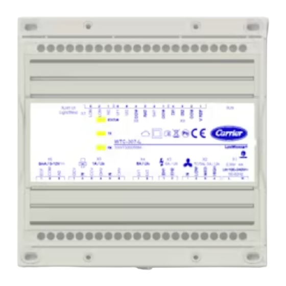
IMPORTANTE: Notare che i moduli di espansione LEX/BEX sono costruiti su una piattaforma simile, ma hanno un tipo e un numero diverso di ingressi e uscite. Figura 1: custodia modulo di espansione WTC-LEX Figure 2: custodia modulo di espansione WTC-BEX... - Page 45 Se il modulo di espansione viene utilizzato ■ ■ espansione a temperatura ambiente per e / o installato in un modo non specificato almeno 24 ore prima dell'installazione per da Carrier Corporation, la funzionalità e la permettere l'evaporazione di eventuale protezione fornita dal modulo di condensa accumulatasi a causa della bassa espansione può essere compromessa. temperatura durante il trasporto/lo Gli ingressi/uscite SELV (bassissima ■...
-
Page 46: Istruzioni Di Montaggio
2. Istruzioni di montaggio Installazione su guida DIN Il modulo di espansione può essere montato su una guida DIN. Il modulo è dotato di 1. Assicurarsi che la guida DIN sia quattro fori di montaggio 7,2 × 4 mm. Il correttamente montata sulla parete. - Page 47 ECx-Lig Table 7- Table Device Dimensions Device Dimensions ECx-Lig 3. Dimensioni dispositivo Mode 132 (5.2) 44 (1.7) 132 (5.2) 44 (1.7) ECx-Lig ECx-Li 132 mm 44 mm ECx-Bli ECx-Li ECx-Bli ECx-Li ECx-Bl Table 7-3 Table (7.2) (7.2) (5.2) (5.2) ECx-Bl 132 mm Model Table...
- Page 48 4. Cablaggio di alimentazione 5. Cablaggio di ingresso Tensione di alimentazione WTC-LEX/-BEX Ogni modulo di espansione dispone di connessioni fisiche per quattro ingressi Modello Tensione (contrassegnati come DIx per ingressi WTC-LEX-WD 100-240 VAC/CC; -15%/+10%; digitali). Tutti i cablaggi di ingresso devono WTC-LEX-ST 50/60 Hz;...
- Page 49 Before connecting any output equipment to the expansion Please refer to the table below for the cross referenc module, refer to the installation guide of the equipment manufacturer. ECx-Light-4DALI-WD marking External connector marki The output wires must remain between 17 AWG (1 mm²) Cablaggio uscite illuminazione ON/OFF Cablaggio uscite tende/tende da sole and 16 AWG (1.5 mm²).
- Page 50 WTC con un cavo RJ-45) non deve superare i 30 m. RJ45-RJ45 (T568A o T568B). La lunghezza max. totale del bus sottorete è Due moduli di espansione WTC-LEX e due 180 m. WTC-BEX possono essere liberamente combinati in una configurazione a catena per controllare fino a 8 uscite illuminazione e fino a 8 uscite tende/tende da sole.
- Page 51 8. Topologia bus sottorete Terminazione di linea EOL: Quando i moduli di espansione WTC-LEX/-BEX e i dispositivi ambientali sono installati con un controllore WTC, solo l'ultimo dispositivo (modulo di espansione o dispositivo ambientale) è impostato su ON. Tutti gli altri...
- Page 52 10. Scarico della trazione e coperchio della morsettiera In alcune giurisdizioni, i coperchi morsettiera sono necessari per la conformità alle normative locali sulla sicurezza. Gli scarichi della trazione e i coperchi della morsettiera sono disponibili per controllori alloggiati in ampie custodie e sono utilizzati per ridurre la tensione sul cablaggio e nascondere i morsetti del controllore.
-
Page 53: Informazioni Complementari
11. Informazioni complementari Questo prodotto non è riparabile. Se ■ fuori uso, restituirlo a Carrier Corporation. Tutti i cavi flessibili installati ■ permanentemente presentano ancoraggio di tipo X. Tutti i cavi devono essere in grado di ■ operare sopra gli 80°C. Questo dispositivo è progettato per ■... -
Page 54: Schemi Elettrici
18. Typical ECx-Light-4D Wiring Diagram 12. Schemi elettrici WTC-LEX-ST / WTC-LEX-WD Gruppo 3 Group 3 Gruppo 4 Group 4 RJ45 UI RJ45 UI Luce/Tenda/WTC Luce/Tenda/WTC LIGHT 3 LIGHT 4 5mA / 0-10V 5mA / 0-10V Load 2A/Output LIGHT 1 LIGHT 2... - Page 55 WTC-BEX-WDLV / WTC-BEX-STLV RJ45 UI RJ45 UI Luce/Tenda/WTC Luce/Tenda/WTC Interruttori Switches Alimentazione 100-240 VAC 100-240 VAC Power Supply...
-
Page 56: Guida Alla Risoluzione Dei Problemi
13. Guida alla risoluzione dei problemi Il modulo di espansione non si accende Il modulo di espansione Verificare che il modulo di espansione sia collegato al controllore è collegato al e che i cavi patch siano inseriti nei connettori. controllore? Il controllore riceve E' possibile che il controllore non stia ricevendo l'alimentazione. alimentazione? Il cavo è... - Page 57 Módulo de iluminación/ persianas WTC-LEX/-BEX Manual de instalación Contenidos del paquete Módulo de expansión para control de ■ iluminación/persianas para controladores WTC (WTC-207-L/-B, WTC-307-L/-B) Precauciones de instalación Requisitos generales de instalación Introducción Después de la instalación, lleve a cabo Este documento describe los ■...
-
Page 58: Descripción General
IMPORTANTE: tenga en cuenta que los módulos de expansión LEX/BEX están construidos sobre una plataforma similar, pero tienen diferentes tipos y número de entradas y salidas. Figura 1: carcasa del módulo de expansión WTC-LEX Figura 2: carcasa del módulo de expansión WTC-BEX... -
Page 59: Requisitos De Instalación
Si el módulo de expansión se utiliza o se ■ ■ expansión se mantengan a temperatura instala de una forma no especificada por Carrier Corporation, la funcionalidad y la ambiente durante al menos 24 horas protección proporcionadas por el módulo antes de la instalación para permitir que de expansión pueden verse perjudicadas. -
Page 60: Instrucciones De Montaje
2. Instrucciones de montaje Instalación montada en el carril DIN El módulo de expansión se puede montar en un carril DIN. El módulo tiene cuatro taladros de 1. Asegúrese de que el carril DIN esté montaje de 7,2 × 4 mm. El módulo de expansión se puede montar en un panel o en montado correctamente en la pared. - Page 61 ECx-Lig Table 7- Table Device Dimensions Device Dimensions ECx-Lig 3. Dimensiones del aparato Mode 132 (5.2) 44 (1.7) 132 (5.2) 44 (1.7) ECx-Lig ECx-Li 132 mm 44 mm ECx-Bli ECx-Li ECx-Bli ECx-Li ECx-Bl Table 7-3 Table (7.2) (7.2) (5.2) (5.2) ECx-Bl 132 mm Model...
-
Page 62: Cableado De Entrada
4. Cableado de alimentación 5. Cableado de entrada Tensión de alimentación del WTC-LEX/-BEX Cada módulo de expansión tiene conexiones físicas para cuatro entradas (marcadas como Modelo Tensión DIx para las entradas digitales). Todo el cableado de entrada debe conectarse con los WTC-LEX- 100-240 VCA/CC;... - Page 63 outputs. All output wiring must be connected using the specified detachable Only for ECx-Light-4DALI-WD: the marking on connectors. Refer to product datasheet for connector information. external connector is different from the module marki Salidas del cableado de iluminación Salidas del cableado de control de Before connecting any output equipment to the expansion Please refer to the table below for the cross referenc module, refer to the installation guide of the equipment...
-
Page 64: Cable De Conexión
WTC, mediante un cable RJ45-RJ45 (T568A RJ-45) no debe exceder de 30 m. o T568B). La longitud máxima total del bus de subred Dos módulos de expansión WTC-LEX y dos es 180 m. WTC-BEX se pueden combinar libremente en una configuración de conexión en serie para controlar hasta 8 salidas de luz y hasta 8 salidas de persiana/sombreado. - Page 65 8. Topología del bus de subred Terminación EOL: cuando los módulos de expansión WTC-LEX/-BEX y los aparatos de la sala se instalan con un controlador de WTC, solo el último aparato (módulo de expansión o aparato de la sala) se configura en ON. Todos los demás módulos de expansión y aparatos de la sala deben tener sus terminaciones EOL configuradas en OFF.
- Page 66 10. Aliviador de tensión mecánica y cubierta del bloque de terminales En algunas jurisdicciones, se requiere que las cubiertas del bloque de terminales cumplan con las normas de seguridad locales. Los aliviadores de tensión mecánica y las cubiertas del bloque de terminales están disponibles para los controladores alojados en cerramientos grandes, y se utilizan para aliviar la tensión mecánica en el cableado y ocultar los terminales de los cables de los controladores.
-
Page 67: Información Complementaria
11. Información complementaria Este producto no es reparable. Si está ■ averiado, se debe devolver a Carrier Corporation. Todos los cables de recorrido instalados ■ de forma permanente presentan un anclaje de tipo X. Todos los cables deben poder funcionar ■ por encima de 80 °C. -
Page 68: Esquema Eléctrico
18. Typical ECx-Light-4D Wiring Diagram 12. Esquema eléctrico WTC-LEX-ST / WTC-LEX-WD Grupo 3 Group 3 Grupo 4 Group 4 RJ45 UI RJ45 UI Luz/Persiana/ Luz/Persiana/ LIGHT 3 LIGHT 4 5mA / 0-10V 5mA / 0-10V Load 2A/Output LIGHT 1 LIGHT 2... - Page 69 WTC-BEX-WDLV / WTC-BEX-STLV RJ45 UI RJ45 UI Luz/Persiana/ Luz/Persiana/ Interruptores Switches Alimentación 100-240 VCA 100-240 VAC Power Supply...
-
Page 70: Guía De Resolución De Problemas
13. Guía de resolución de problemas El módulo de expansión no se enciende ¿Está conectado el Compruebe que el módulo de expansión esté conectado al módulo de expansión al controlador y que los cables de conexión estén enchufados a los controlador? conectores. ¿Se está suministrando Es posible que no se esté... - Page 71 Verlichtings- en zonweringsmodule WTC-LEX/-BEX Montagehandleiding Inhoud van de verpakking Uitbreidingsmodule voor verlichting en ■ zonwering voor WTC regelaars (WTC-207-L/-B, WTC-307-L/-B) Voorzorgsmaatregelen Algemene installatie-eisen Inleiding Voer na de installatie een complete In dit document staan de instructies voor ■ systeemcontrole uit en leg alle functies de installatie van WTC-verlichtings- en van het systeem uit aan de gebruiker.
-
Page 72: Algemene Beschrijving
1. Overzicht van WTC-LEX/-BEX modules Algemene beschrijving De WTC-LEX uitbreidingsmodule is WTC-verlichtings- en verkrijgbaar in twee configuraties: zonweringsuitbreidingsmodules zijn bestemd WD: 100-240 VAC - snelconnectors om de WTC-regelaar uit te breiden met ■ (WTC-LEX-WD) maximaal acht stuurcommando's voor ST: 100-240 VAC - afneembare verlichting en zonwering. - Page 73 ■ ■ en/of geïnstalleerd op een manier die niet uitbreidingsmodule(s) ten minste 24 uur door Carrier Corporation is aangegeven, voor de installatie op kamertemperatuur te kunnen de werking en de bescherming van brengen zodat eventueel condenswater dat de uitbreidingsmodule nadelig worden zich tijdens transport bij lage temperaturen beïnvloed.
-
Page 74: Montage-Instructies
2. Montage-instructies Installatie op DIN-rail De uitbreidingsmodule kan worden gemonteerd op een DIN-rail. De module heeft vier 1. Zorg ervoor dat de DIN-rail correct aan montagegaten 7,2 × 4 mm. De de wand is gemonteerd. uitbreidingsmodule kan worden gemonteerd op 2. - Page 75 ECx-Lig Table 7- Table Device Dimensions Device Dimensions ECx-Lig 3. Afmetingen Mode 132 (5.2) 44 (1.7) 132 (5.2) 44 (1.7) ECx-Lig ECx-Li 132 mm 44 mm ECx-Bli ECx-Li ECx-Bli ECx-Li ECx-Bl Table 7-3 Table (7.2) (7.2) (5.2) (5.2) ECx-Bl 132 mm Model Table Table 7-...
- Page 76 WTC-BEX-WDLV 100-240 VAC; -15%/+10%; WTC-BEX-STLV 50/60 Hz; Overspanninsgcategorie Digitaal potentiaalvrij II - 2,5 kV contact WTC-LEX/-BEX opgenomen vermogen NO-NG Model Normaal Max. verbruik Afbeelding 8: Digitale ingang – potentiaalvrij contact verbruik (NO-NG) - Gereserveerd voor toekomstig gebruik WTC-LEX-WD...
- Page 77 manufacturer. ECx-Light-4DALI-WD marking External connector marki The output wires must remain between 17 AWG (1 mm²) and 16 AWG (1.5 mm²). Make sure the cable performances suit the connected loads. Bedrading AAN/UIT Bedrading 24 VDC zonweringsuitgangen Table 9-1: Expansion Module Outputs verlichtingsuitgangen Elke 24 VDC zonweringsuitgang kan 24 Expansion...
- Page 78 BEX uitbreidingsmodules / RJ45- WTC-subnetwerkapparaat door middel van een accessoires) mag niet langer zijn dan 30 m. RJ45-RJ45 kabel (T568A of T568B). Twee WTC-LEX en twee WTC-BEX De totale max. lengte van de subnetwerkbus uitbreidingsmodules kunnen vrijelijk worden is 180 m.
- Page 79 DIP-switch is ingesteld op 0. Subnet-ID EOL-afsluiting BELANGRIJK: Als u een tweede uitbreidingsmodule van hetzelfde type aansluit, Afbeelding 13: Instellen van het WTC-LEX/-BEX moet u handmatig een van de uitbreidingsmodules subnet-ID-adres instellen op een ander ongebruikt subnet-ID-adres. Er worden drie subnet-ID-coderingen...
- Page 80 10. Trekontlasting en afdekkap over het klemmenblok In sommige landen zijn afdekkappen over het klemmenblok verplicht. Trekontlasting en afdekkappen over het klemmenblok zijn verkrijgbaar voor regelaars in grote behuizingen en worden gebruikt om de trekkracht van de bedrading op te vangen en de aansluitklemmen van de regelaar af te schermen.
-
Page 81: Aanvullende Informatie
11. Aanvullende informatie Dit product kan niet worden ■ gerepareerd. Als het defect is, moet het worden teruggestuurd naar Carrier Corporation. Alle permanent gemonteerde ■ transportkabels hebben een X-type anker. Alle kabels moeten bestand zijn tegen ■ temperaturen boven 80°C. - Page 82 18. Typical ECx-Light-4D Wiring Diagram 12. Bedradingsschema's WTC-LEX-ST / WTC-LEX-WD Groep 3 Group 3 Groep 4 Group 4 RJ45 UI RJ45 UI Licht/Zonwering/ Licht/Zonwering/ LIGHT 3 LIGHT 4 5mA / 0-10V 5mA / 0-10V Load 2A/Output LIGHT 1 LIGHT 2...
- Page 83 WTC-BEX-WDLV / WTC-BEX-STLV RJ45 UI RJ45 UI Licht/Zonwering/ Licht/Zonwering/ Schakelaars Switches 100-240 VAC elektrische voeding 100-240 VAC Power Supply...
-
Page 84: Problemen Oplossen
13. Problemen oplossen Uitbreidingsmodule schakelt niet in Is de uitbreidingsmodule Controleer of de uitbreidingsmodule is aangesloten op de regelaar en of de aangesloten op de regelaar? patchkabels in de aansluitingen zitten. Krijgt de regelaar elektrische Misschien krijgt de regelaar geen voeding. voeding? Is de kabel aangesloten op Controleer of de RJ-45-stekkers correct aan de kabel zijn gemonteerd. - Page 85 Moduł systemu oświetlenia / osłon przeciwsłonecznych WTC-LEX/-BEX Instrukcja instalacji Zawartość opakowania Moduł rozszerzeń systemu oświetlenia / ■ osłon przeciwsłonecznych do sterowników WTC (WTC-207-L/-B, WTC-307-L/-B) Środki ostrożności podczas instalacji Ogólne warunki instalacji Wstęp Po zakończeniu instalacji należy W niniejszym dokumencie opisano procedury ■ przeprowadzić kompletną kontrolę instalacji sprzętu dla modułów rozszerzeń systemu i wyjaśnić użytkownikowi systemu oświetlenia WTC / osłon wszystkie jego funkcje. przeciwsłonecznych serii WTC-207/-307 w Wszystkie elementy opakowania standardach LON i BACnet. Przed ■ zamontowaniem urządzenia należy dokładnie muszą być usunięte zgodnie z obowiązującymi przepisami lokalnymi. zapoznać się z zaleceniami zamieszczonymi w instrukcji. Producent nie ponosi...
-
Page 86: Opis Ogólny
1. Ogólne informacje o modułach WTC-LEX/-BEX Opis ogólny Moduł rozszerzeń WTC-LEX jest dostępny w dwóch konfiguracjach: Moduły rozszerzeń WTC do systemu WD: 100-240 VAC - Szybkozłącze oświetlenia / osłon przeciwsłonecznych ■ (WTC-LEX-WD) zaprojektowano w celu uzupełnienia ST: 100-240 VAC - Odłączane złącza sterownika WTC o maksymalnie osiem ■ (WTC-LEX-ST) poleceń dotyczących oświetlenia i osiem poleceń dotyczących żaluzji / osłon Moduł rozszerzeń WTC-BEX LV jest przeciwsłonecznych. Moduły rozszerzeń dostępny w dwóch konfiguracjach: działają na osobnej magistrali podrzędnej, WD: 100-240 VAC - Szybkozłącze ■... - Page 87 Wymogi instalacyjne ■ Jeżeli moduł rozszerzeń jest używany i/lub instalowany w sposób inny niż określony ■ Zaleca się, aby moduł (moduły) rozszerzeń przez Carrier Corporation, może nastąpić pozostawał (pozostawały) w temperaturze utrata funkcjonalności i ochrony pokojowej przez co najmniej 24 godziny zapewnianej przez moduł rozszerzeń. przed instalacją, aby umożliwić ■ Wejścia/wyjścia SELV (zabezpieczone odparowanie skroplin, które mogły się obwody niskonapięciowe) muszą być nagromadzić z powodu niskiej temperatury podłączone do urządzeń klasy 3 lub sekcji podczas transportu/magazynowania. SELV urządzeń klasy 2. ■ Jeśli moduł ma być zamontowany na ■ W chwili rozpakowywania produktu należy wsporniku metalowym, ten sam wspornik sprawdzić zawartość kartonu pod kątem metalowy musi zostać podłączony do uszkodzeń powstałych podczas transportu. uziemienia ochronnego. Nie instalować uszkodzonych modułów. ■ Moduły WD mogą być montowane na ■ Unikać miejsc, w których mogą ścianie lub na szynie DIN. Przewody występować pary, opary lub gazy o muszą być niedostępne, a okablowanie działaniu korodującym, niszczącym lub musi być zgodne z miejscowymi wybuchowym.
-
Page 88: Instrukcja Montażu
2. Instrukcja montażu Instalacja montowana na szynie DIN Moduł rozszerzeń może być montowany na szynie DIN. Moduł posiada cztery otwory 1. Upewnić się, że szyna DIN jest montażowe 7,2 × 4 mm. Moduł rozszerzeń prawidłowo zamontowana na ścianie. można zamontować na panelu lub na ścianie 2. Zatrzasnąć moduł rozszerzeń na szynie przy użyciu odpowiednich śrub (stosować DIN. odpowiednio blachowkręty, wkręty kształtowe lub wkręty samogwintujące). Przed rozpoczęciem jakichkolwiek czynności obsługowych należy wyłączyć zasilanie. W przypadku niektórych modeli, jeżeli moduł rozszerzeń ma być zainstalowany poza skrzynką elektryczną, konieczne jest zastosowanie opcjonalnego odciążenia naciągu i pokrywy listwy zacisków. WAŻNE: W niektórych modelach nie wszystkie Rysunek 3: Moduł rozszerzeń zamontowany na otwory montażowe mogą być dostępne. W szynie każdym przypadku można jednak użyć co... - Page 89 ECx-Lig Table 7- Table Device Dimensions Device Dimensions ECx-Lig 3. Wymiary urządzenia Mode 132 (5.2) 44 (1.7) 132 (5.2) 44 (1.7) ECx-Lig ECx-Li 132 mm 44 mm ECx-Bli ECx-Li ECx-Bli ECx-Li ECx-Bl Table 7-3 Table (7.2) (7.2) (5.2) (5.2) ECx-Bl 132 mm Model Table...
- Page 90 4. Przewody zasilające 5. Przewody wejściowe Każdy moduł rozszerzeń posiada fizyczne Napięcie zasilania WTC-LEX/-BEX połączenia dla czterech wejść (oznaczone Model Napięcie jako DIx dla wejść cyfrowych). Wszystkie WTC-LEX-WD 100-240 VAC/DC; -15%/+10%; przewody wejściowe muszą być podłączone WTC-LEX-ST 50/60 Hz; za pomocą odłączanych złączy Tylko do zasilania wyjść dostarczonych w zestawie. oświetlenia. Moduł jest zasilany przez podsieć. Okablowanie wejść cyfrowych (DIx) Kategoria przepięciowa II - 2,5 kV WTC-BEX-WDLV 100-240 VAC; -15%/+10%; Konfiguracja wejścia jest wykorzystywana WTC-BEX-STLV 50/60 Hz; Kategoria przepięciowa do monitorowania cyfrowych styków II - 2,5 kV bezpotencjałowych. Napięcie zasilania WTC-LEX/-BEX Cyfrowy styk bezpotencjałowy...
- Page 91 high voltage shade / sunblind outputs and 24 VDC shade / sunblind The starting current must be kept under 80 A during 20 ms. outputs. All output wiring must be connected using the specified detachable Only for ECx-Light-4DALI-WD: the marking on connectors.
- Page 92 7. Przewody komunikacyjne podsieci Moduły rozszerzeń WTC-LEX/-BEX działają Długość przewodu pomiędzy każdym na osobnej magistrali podrzędnej podłączonej urządzeniem podsieciowym (sterownik do złącza podsieci RJ-45 kompatybilnego WTC / moduły rozszerzeń WTC-LEX/-BEX / urządzenia podsieciowego WTC za pomocą akcesoria RJ-45) nie powinna przekraczać przewodu RJ45-RJ45 (T568A lub T568B). 30 m. Dwa moduły rozszerzeń WTC-LEX i dwa moduły rozszerzeń WTC-BEX można dowolnie łączyć w Łączna maks. długość magistrali podsieciowej konfiguracji łańcuchowej w celu sterowania wynosi 180 m. maks. 8 wyjściami oświetlenia i maks. 8 wyjściami żaluzji / osłon przeciwsłonecznych. Podsieć przewodowa Cat5e Sterownik WTC Urządzenia pokojowe...
- Page 93 W związku z tym, ten sam identyfikator Położenie przełącznika Adres podsieci można przypisać do modułów identyfikujący rozszerzeń WTC-LEX/-BEX (moduły podsieć rozszerzeń oświetlenia / osłon OFF OFF OFF OFF 0 przeciwsłonecznych), WTC-ISP/-ISPL OFF OFF OFF 1 (WTC-LEX (czujniki wielofunkcyjne na podczerwień), moduł #2) WTC-RT (czujnik temperatury pokojowej) OFF ON OFF OFF 2 (WTC-LEX lub serii WTC-RCI (interfejsy regulatora moduł #1) pokojowego), nie powodując żadnych OFF OFF 3 (WTC-BEX problemów związanych z adresowaniem. moduł #2) OFF OFF ON OFF 4 (WTC-BEX moduł #1)
- Page 94 10. Odciążenie naciągu i pokrywa listwy zacisków W niektórych systemach prawnych do spełnienia lokalnych przepisów bezpieczeństwa wymagane są pokrywy listew zaciskowych. Do sterowników umieszczonych w dużych obudowach dostępne są odciążenia naciągu i pokrywy listew zaciskowych, które służą do zmniejszenia naprężeń przewodów i ukrycia zacisków przewodów sterowników. Odciążenia i pokrywy listew zaciskowych są opcjonalne i sprzedawane jako urządzenia peryferyjne. Zastosowanie odciążenia i pokrywy listwy zaciskowej nie jest Rysunek 16: Podłączanie przewodów do możliwe w przypadku montażu na szynie DIN. odciążenia naciągu WAŻNE: Odciążenie naciągu i pokrywa listwy zaciskowej nie mogą być używane z modelami –WD. Przed podłączeniem wszystkich przewodów zaleca się zamontowanie odciążenia naciągu. Do tego montażu dostarczone są w zestawie dwie śruby. Patrz dolna część obudowy, jak pokazano na rysunku 14 poniżej. Rysunek 17: Podłączanie przewodów do odciążenia naciągu (zakończone) W razie potrzeby pokrywę listwy zaciskowej można przymocować do odciążenia naciągu, jak pokazano poniżej.
- Page 95 11. Informacje uzupełniające Ten produkt nie podlega naprawie. Jeśli ■ nie działa prawidłowo, musi być zwrócony do Carrier Corporation. We wszystkich przewodach jezdnych ■ występuje zakotwienie typu X. Wszystkie przewody muszą posiadać ■ zdolność do pracy w temperaturze powyżej 80°C. To urządzenie jest przeznaczone do ■ działania typu 1. To urządzenie jest przeznaczone do ■ działania typu 1.b. Temperatura próby ciśnieniowej kuli ■ wynosi 75°C. W tym urządzeniu występuje ■ oprogramowanie klasy A. SELV nie przekracza 42 VDC. ■ Maksymalne dostępne napięcie wynosi ■ 16 VDC.
- Page 96 18. Typical ECx-Light-4D Wiring Diagram 12. Schematy okablowania WTC-LEX-ST / WTC-LEX-WD Group 3 Group 4 RJ45 UI RJ45 UI Oświetlenie/ Oświetlenie/ LIGHT 3 LIGHT 4 Osłony okienne/ Osłony okienne/WTC 5mA / 0-10V 5mA / 0-10V Load 2A/Output LIGHT 1 LIGHT 2 TOTAL 6A max...
- Page 97 WTC-BEX-WDLV / WTC-BEX-STLV RJ45 UI RJ45 UI Oświetlenie/ Oświetlenie/ Osłony okienne/ Osłony okienne/ Switches 100-240 VAC Power Supply...
- Page 98 13. Instrukcja wykrywania i usuwania usterek Moduł rozszerzeń nie włącza się Czy moduł rozszerzeń jest Sprawdzić, czy moduł rozszerzeń jest podłączony do sterownika i czy podłączony do sterownika? kable krosowe są wetknięte w złącza. Czy do sterownika jest Do sterownika może nie być dostarczane zasilanie. dostarczane zasilanie? Czy kabel jest podłączony Sprawdzić, czy złącza zaciskowe RJ-45 zostały prawidłowo do sterownika i modułu zainstalowane na kablu. Patrz "Okablowanie komunikacyjne podsieci" rozszerzeń? na stronie 8. Czy kabel krosowy został Sprawdzić, czy złącza zaciskowe RJ-45 zostały prawidłowo wykonany na miejscu? zainstalowane na kablu. Patrz "Okablowanie komunikacyjne podsieci" na stronie 8. Moduł rozszerzeń nie nawiązuje łączności ze sterownikiem Czy adres został W każdym module rozszerzeń musi być ustawiony unikatowy adres dla prawidłowo ustawiony jako każdego sterownika. Patrz "Adresowanie urządzenia" na stronie 9. unikatowy? Czy urządzenie znajduje Sprawdzić odległość pomiędzy modułem rozszerzeń a następnym i...
- Page 99 Lidická 323 - 266 39 Beroun 3 - Czech Republic Order No.: X0081, 02.2017 - Supersedes order No.: X0081, 07.2015 The manufacturer reserves the right to change any product specifications without notice. Printed in the European Union.
Need help?
Do you have a question about the WTC-LEX and is the answer not in the manual?
Questions and answers