Table of Contents

Related Manuals for NXP Semiconductors BGU7003


Summary of Contents for NXP Semiconductors BGU7003
- Page 1 UM10339 User Manual for the BGU7003 GPS LNA demo boards v2.0 Rev. 1 — 15 September 2011 User manual Document information Info Content Keywords LNA, GPS, BGU7003 Abstract This document explains the BGU7003 GPS LNA evaluation Board...
- Page 2 UM10339 NXP Semiconductors User manual Revision history Date Description 20110915 Initial document Contact information For more information, please visit: http://www.nxp.com For sales office addresses, please send an email to: salesaddresses@nxp.com UM10339 All information provided in this document is subject to legal disclaimers.
-
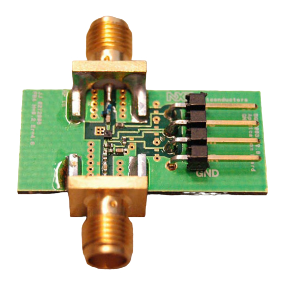
Page 3: Fig 1. Bgu7003_Gps Lna Evaluation Board
It also contains a power down function to shutdown the amplifier by means of a logic signal on the enable pin. The BGU7003 is ideal for use in portable electronic devices, such as mobile phones, Personal Digital Assistants (PDAs), Personal Navigation Devices (PNDs) etc. -
Page 4: Fig 2. Simplified Internal Circuit Of The Bgu7003
RFout Fig 2. Simplified internal circuit of the BGU7003 The BGU7003 is not internally matched so for both input and output a matching circuit needs to be designed. The fact that no internal matching is available makes the product suitable for different application areas. -
Page 5: Fig 3. Circuit Diagram Of The Evaluation Board
3.2 Board layout Figure Fig 4 shows the board layout with the component identifiers. Fig 4. Printed-Circuit Board (PCB) of the BGU7003 evaluation board UM10339 All information provided in this document is subject to legal disclaimers. © NXP B.V. 2011. All rights reserved. -
Page 6: Fig 5. Stack Of The Pcb Material
A good PCB Layout is an essential part of an RF circuit design. The EVB of the BGU7003 can serve as a guideline for laying out a board using the BGU7003. Use controlled impedance lines for all high frequency inputs and outputs. Bypass V with decoupling capacitors, preferable located as close as possible to the device. -
Page 7: Required Equipment
A noise figure analyzer. 5. Connections and set_up The BGU7003 EVB is fully assembled and tested. Please follow the steps below for a step-by-step guide to operate the EVB and testing the device functions. 1. Connect the DC power supply set to 2.5 V to the V and GND terminals. -
Page 8: Fig 6. Evaluation Board Including Its Connections
UM10339 NXP Semiconductors User manual Fig 6. Evaluation board including its connections UM10339 All information provided in this document is subject to legal disclaimers. © NXP B.V. 2011. All rights reserved. User manual Rev. 1 — 15 September 2011 8 of 13... -
Page 9: Typical Evb Results
UM10339 NXP Semiconductors User manual 6. Typical EVB results Table 2. Typical results measured on the evaluation boards Operating frequency is 1575.42 MHz; V and V = 2.5 V; I = 5 mA; T = 25 °C; unless otherwise specified. -
Page 10: Legal Information
Export might require a prior In no event shall NXP Semiconductors be liable for any indirect, incidental, authorization from national authorities. punitive, special or consequential damages (including - without limitation - Evaluation products —... -
Page 11: Table Of Contents
8. List of figures Fig 1. BGU7003_GPS LNA evaluation board ..... 3 Fig 2. Simplified internal circuit of the BGU7003 ..4 Fig 3. Circuit diagram of the evaluation board .... 5 Fig 4. Printed-Circuit Board (PCB) of the BGU7003 evaluation board .......... -
Page 12: List Of Tables
NXP Semiconductors User manual 9. List of tables Table 1. BOM of the BGU7003 evaluation board .... 6 Table 2. Typical results measured on the evaluation boards 9 UM10339 All information provided in this document is subject to legal disclaimers. -
Page 13: Contents
UM10339 NXP Semiconductors User manual 10. Contents Introduction ............3 General description ..........4 Application board ..........4 Application circuit ..........5 Board layout ............5 PCB layout ............6 Bill of materials ........... 6 Required equipment ..........7 Connections and set_up ........7 Typical EVB results ..........
Need help?
Do you have a question about the BGU7003 and is the answer not in the manual?
Questions and answers