Table of Contents
Advertisement
Quick Links
Advertisement
Table of Contents

Related Manuals for Scaime D2452


Summary of Contents for Scaime D2452
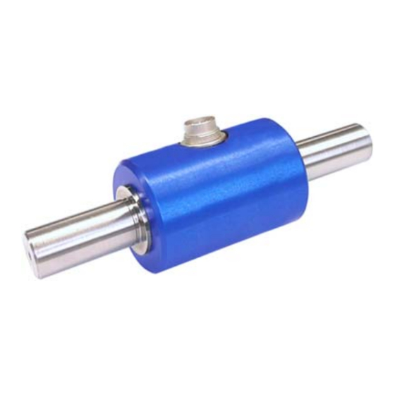
- Page 1 Operation Manual for Non Rotating Torque Sensors For D2452...
- Page 2 References in this Text 1.6 Warning Notes; Page 4 Attention must be paid to the accident prevention regulations of the trade associations. During operation the safety precautions must be serviceable. 4 Mechanical Assembly; Page 6 Caution: Impermissible large torques, bending moments or axial forces may not act on the sensor or the couplings.
-
Page 3: Table Of Contents
Contents Read First.............................. 4 Safety and Caution Symbols......................4 Intended Use..........................4 Dangers............................4 1.3.1 Neglecting of Safety Notes ..................... 4 1.3.2 Remaining Dangers ........................ 4 Reconstructions and Modifications ....................4 Personnel ............................4 Warning Notes ..........................4 Term Definitions ............................ 5 Terms ............................. -
Page 4: Read First
Read First Safety and Caution Symbols Caution: Injury Risk for Persons Damage of the Device is possible. Note: Important points to be considered. Intended Use Torque sensors are intended for the measurement of torques. This measurand is further suitable for control tasks. -
Page 5: Term Definitions
Term Definitions Terms Measuring Side: Shaft connection in which the torque to be measured is applied. Usually this side has the smallest moment of inertia. Drive Side: The shaft end on the opposite side of the measuring side with the larger moment of inertia. At static torque sensors the housing is fastened on this side. -
Page 6: Mechanical Assembly
4.1.1 Examples Single-Jointed Couplings For this torque sensor we recommend the couplings intended by Scaime which must be able to balance an axial, radial or angular offset of the shafts and not allow large forces to act on the sensor. -
Page 7: Double-Jointed Couplings
4.1.3 Double-Jointed Couplings Double-jointed couplings are used for the balance of inevitable angular, axial and radial misalignments. Angular Misalignments Axial Misalignments 4.1.4 Alignment of the Measurement Arrangement Precisely alignment of the couplings reduces the reaction forces and increases the durability of the couplings. -
Page 8: Torque Sensors Of 0,03 N·m To 15 N·m
Measuring The shaft is fixed side in the housing Double-jointed coupling Setup-Example: the sensor is being supported at the housing and the torque is led in on the measuring side through a double-jointed coupling. 4.2.3 Torque Sensors of 0,03 N·m to 15 N·m Sensors with nominal torques below 50 N·m are very sensitive to overload, therefore these sensors need to be handled with greatest caution. -
Page 9: Torque Sensor From 20 N·m
Maximum Forces Maximum force F on a lever in distance r from the axis. Nominal Torque r = 10 mm r = 20 mm r = 50 mm of the Sensor 0,03 N·m 1,5 N 0,6 N 0,05 N·m 2,5 N Shaft 0,1 N·m 10 N... -
Page 10: Electrical Connection
Electrical Connection Pin Connection 6-pin Function SG- excitation - SG- excitation + Shield SG- signal + SG- signal - 100% calibration control 7-pin Function SG- excitation - SG- excitation + Shield SG- signal + SG- signal - 100% calibration control View: socket on soldering side Cable Only use a shielded cable with preferably small capacity. -
Page 11: Running Of Measuring Cables
Torque means clockwise or clockwise torque if the torque acts clockwise when facing the shaft end. In this case a positive electrical signal is obtained at the output. Torque sensors by Scaime can measure both, clockwise and counter-clockwise direction. Static / Quasi-Static Torques Static and/or quasi-static torque is a slowly changing torque. -
Page 12: Disturbance Variables
Disturbance Variables By disturbances, measured value falsifications can occur by • Vibrations, • Air motions at small torques, • Temperature gradients in the torque sensor, • Temperature changes, • Electrical disturbances, • Magnetic disturbances, • EMC (electromagnetic disturbances), Therefore avoid these disturbance variables by decoupling of vibrations, covers, etc. Calibration Control (Option) Supply + By a control resistance, a signal is generated in the... -
Page 13: Maintenance
The sensor should be tidily packed into film. Larger sensors should be packed in cases. Storage The storage of the sensors must occur in dry, dust-free rooms, only. Slightly lubricate shafts and flanges with oil before storing (rust). NU-D2452-E-1107...
Need help?
Do you have a question about the D2452 and is the answer not in the manual?
Questions and answers