Table of Contents
Advertisement
Quick Links
Advertisement
Table of Contents

Subscribe to Our Youtube Channel
Related Manuals for Scaime DV14 Series


Summary of Contents for Scaime DV14 Series
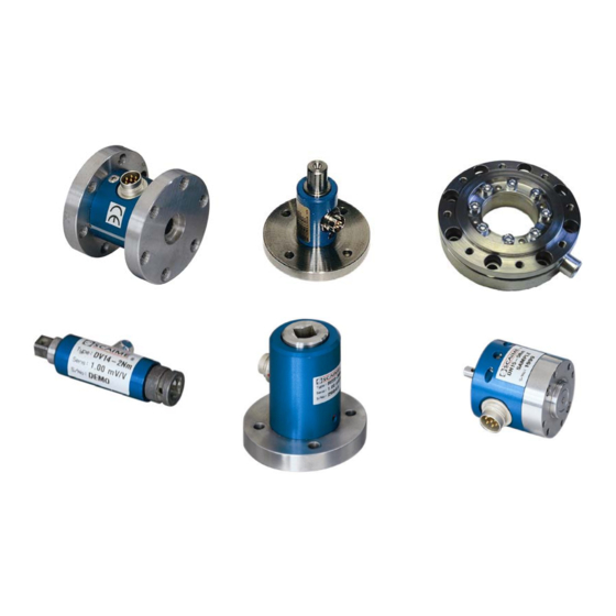
- Page 1 Non Rotating Torque Sensors For below and similar Types Series : DV14 / DF30 / DF2553 / DH15 / DFW / D2223 / D2268 SCAIME SAS tél : 33 4 50 87 78 64 294, rue Georges Charpak fax : 33 4 50 87 78 46 74105 ANNEMASSE Cedex France www.scaime.com...
- Page 2 Modification Technical changes reserved. References in this Text 1.6 Warning Notes; Page 4 Attention must be paid to the accident prevention regulations of the trade associations. During operation the safety precautions must be serviceable. 4 Mechanical Assembly; Page 6 Caution: During the assembly inadmissibly large forces may not act on the sensor or the couplings.
-
Page 3: Table Of Contents
Contents Read First .............................. 4 Safety and Caution Symbols ......................4 Intended Use ..........................4 Dangers ............................4 1.3.1 Neglecting of Safety Notes ..................... 4 1.3.2 Remaining Dangers ........................ 4 Reconstructions and Modifications ....................4 Personnel ............................4 Warning Notes ..........................4 Term Definitions ............................ -
Page 4: Read First
Read First Safety and Caution Symbols Caution: Injury Risk for Persons Damage of the Device is possible Note: Important points to be considered Intended Use Torque sensors are intended for the measurement of torques. This measurand is further suitable for control tasks. -
Page 5: Term Definitions
Term Definitions Terms Measuring Side: Shaft connection in which the torque to be measured is applied. Usually this side has the smallest moment of inertia. Drive Side: The shaft end on the opposite side of the measuring side with the larger moment of inertia. At this type of torque sensors the housing is fastened on this side. -
Page 6: Mechanical Assembly
Mechanical Assembly Caution: During the assembly inadmissibly large forces may not act on the sensor or the couplings. At small torques (< 20 N·m) connect the sensor electrically during the assembly and observe the signal, the measurement signal may not exceed the limit values During the assembly the sensor must be supported to protect it from falling down. -
Page 7: Electrical Connection
Electrical Connection Pin Connection 6-pin Function SG- excitation - SG- excitation + Shield SG- signal + SG- signal - 100% calibration control 7-pin Function SG- excitation - SG- excitation + Shield SG- signal + SG- signal - 100% calibration control View: socket on soldering side Free Cable Ends Wire... -
Page 8: Extension Cable
Extension Cable Caution: depending on bridge resistance and wire cross section, the measuring cable length enters into the characteristic value of the sensor. Running of Measuring Cables Do not run measuring cables together with control or heavy-current cables. Always assure that a large distance is kept to engines, transformers and contactors, because their stray fields can lead to interferences of the measuring signals. -
Page 9: 6.4.2 Natural Resonances
6.4.2 Natural Resonances Estimate of the mechanical natural frequencies: = Natural frequency in Hz ⋅ ⋅ = Moment of inertia in kg*m² π ⋅ = Torsional rigidity in Nm/rad Further methods for the calculation of natural resonances are corresponding purchasable programs or books (e.g. -
Page 10: Maintenance
Maintenance Maintenance Schedule Action Frequency Date Date Date Control of cables and connectors 1x p.a. Calibration < 26 months Control of fixation (flanges, shafts) 1x p.a. Trouble Shooting This chart is used for searching for the most frequent errors and their elimination. Problem Possible Cause Trouble Shooting...
Need help?
Do you have a question about the DV14 Series and is the answer not in the manual?
Questions and answers