
Subscribe to Our Youtube Channel
Related Manuals for Scaime IPB 50


Summary of Contents for Scaime IPB 50
- Page 1 WEIGHING INDICATOR IPB 50 Available for version 1.05 or more INSTRUCTION MANUAL SCAIME SAS tel : 33 (0) 4 50 87 78 64 BP501 fax : 33 (0) 4 50 87 78 46 .scaime.com 74105 ANNEMASSE FRANCE WEB SITE :...
-
Page 2: Table Of Contents
IPB50 INDEX INTRODUCTION ......................page 2 SPECIFICATIONS .......................page 3 POWER SUPPLY & START-UP ..................page 4 FRONT PANEL KEYS AND INDICATORS ..............page 5 IPB50 BASIC FUNCTIONS ...................page 6 USER SET-UP......................page 7 TECHNICAL CONFIGURATION.................. page 15 SERIAL OUTPUTS ....................page 21 CONNECTIONS ......................page 25 EXAMPLE OF IPB50 PRINTING ................. -
Page 3: Introduction
IPB50 INTRODUCTION This manual has been created to describe all functional capabilities of the IPB50 indicator and assist you during its installation and set up. The IPB50 besides having all the functions of a high precision weight indicator has weight totalization and piece counting functions. -
Page 4: Specifications
IPB50 SPECIFICATIONS... -
Page 5: Power Supply & Start-Up
IPB50 POWER SUPPLY & START UP The IPB50 is normally charged with a 12 to 25 Vdc ( 7W max.) tension supplied from an AC/DC external charger (supplied) which should be connected to the 230 Vac mains voltage. Safety norms must be respected for the connection to the main voltage including the use of a line, which has to be free from noise generated by other electronic equipment. -
Page 6: Front Panel Keys And Indicators
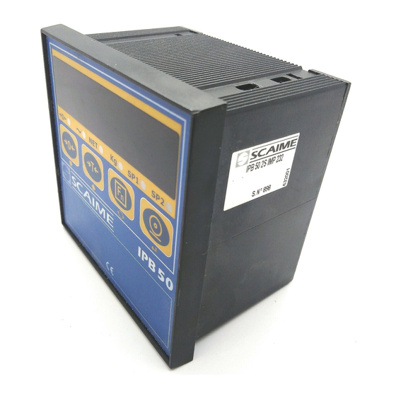
IPB50 FRONT PANEL KEYS AND INDICATORS – IPB50 The front panel of the IPB50 is designed for quick but simple weighing applications. It consists of an LED display with 6 easy to read digits, 13 mm in height, 6 LED indicators, and below a 4 key, polycarbonate, water- resistant membrane . -
Page 7: Ipb50 Basic Functions
IPB50 IPB50 BASIC FUNCTIONS SEMI-AUTOMATIC TARE By pressing the TARE key any weight value present on the display is zeroed, the “NET” LED will now turn on. To cancel the stored tare value, press TARE or ZERO without load. Each subsequent pressing of TARE will replace the previously stored value. -
Page 8: User Set-Up
IPB50 USER SET-UP “SEt” If the user wishes to program any of these specific parameters, he must first enter into USER SET-UP by keeping ↵ pressed while turning the instrument on (pressing the ON key) until the display indicates "SEt." The functions of the following keys, under USER SET-UP, allow the user to: ->0<- Scan the programming steps. - Page 9 IPB50 Analog output (option) AOUt AO g Functioning with analog output on the gross weight AO n1 Functioning with analog output on the net weight (see below) AO n2 Functioning with analog output on the net weight " AO n1 Functioning with analog output on the net weight "...
- Page 10 IPB50 (*) IntES Int no does not print the heading Int SI prints the heading if the total is zero (in reference to the totalization programs)*. IntF1 always prints the heading * the selection of this data involves also the heading configuration (see the PRINT HEADING paragraph in the IPB50 BASIC FUNCTIONS chapter).
- Page 11 IPB50 SELECTABLE OPERATING In addition to the STANDARD weighing Fn, with the basic abilities of TARE deduction and transmission of data (to printer, PC, or remote unit), the IPB50 series indicators can perform one of the following selectable functions: SIMPLE DISPLAY, HOLD, PEAK, ACCUMULATION TOTALIZER, BATCHING TOTALIZER, PIECE COUNTING, STANDARD, NET/GROSS, GROSS WEIGHT SET POINT, NET WEIGHT SET POINT.
- Page 12 IPB50 PRINTING IN EITHER TOTALIZER If a printer is connected, each pressing of Fn prints the progressive number of weighments, the weight GROSS weight and weight. TARE Each time you press PRINT, the TOTAL number of weighments, TOTAL NET weight, TICKET No and DATE/TIME (if selected and it depends of the printer) are printed.
- Page 13 IPB50 VIEWING THE APW (average piece Weight) After carrying out the reference operation it is possible to view on the display the calculated APW or the one manually inserted. While the scale shows the number of pieces, if one presses Fn, the display shows the WEIGHT on the weighing system;...
- Page 14 IPB50 – Increase the value using the ->T<- key. – When finished entering the values, confirm with ↵. – The display shows " SP1On " (relay 1 ENABLING SETPOINT): enter the weight value as in the preceding SETPOINT and confirm with ↵. –...
- Page 15 IPB50 4 / 20 mA MAKE SURE THAT THE JUMPER, ON THE ANALOGIC BOARD IS CLOSED. Connect the digital multimeter on the terminal board 0 / 20 , 4 / 20 mA of the analog output (refer to terminal board connections on the IPB50’s back). Through the AOMA, AOZE, and AOMI steps, adjust the output voltage value which one wants in respect to the f.s.
-
Page 16: Technical Configuration
IPB50 Authorized Personnel Only TECHNICAL CONFIGURATION (SET-UP ENVIRONMENT) Entering the CONFIGURATION or "ConF” Fn of the IPB50 allows you to browse through a menu where it is possible to select all of the instrument’s operating parameters or functions. It is composed of several steps. To enter into CONFIGURATION keep the ->0<- key pressed while turning on the instrument until the display shows "ConF", then release ->0<-. - Page 17 IPB50 dECI (*) DECIMAL POINT POSITION This step moves the position of the decimal point in the scale capacity value chosen from the previous step. (For example, the scale capacity value “15000” would become 1500.0, 150.00, 15.000 depending on which of the values: “100000, 1.0, 1.00, or 1.000”...
- Page 18 IPB50 GrAV (*) SELECTION OF THE GRAVITATIONAL ZONE OF USE The gravitation coefficient varies from location to location throughout the earth’s surface; therefore, its value is not a “constant”. Because it varies between 9.75001 TO 9.84999m/s², the user has the ability to enter the five digits after the decimal point by first selecting ZONE 06 from the list of 6 available zones.
- Page 19 IPB50 UnIt (*) MEASURE UNIT SELECTION Allows user to select which unit of measure will be printed: g / kg / t / Lb. (!) kg M0dE FILTERING – DISPLAYING The 9 possible programmable values are the following: HI-1 HI-2 HI-3 = maximum immunity to vibrations, the display update slower, but with longer gaps. HS-1 HS-2 HS-3 = medium filter, continuous variations of the weight.
- Page 20 IPB50 STOP DATA BIT This is used to select one of the following communication protocols: N-8-I / N-8-2 / N-7-2 / E-7-I / E-7-2. (!) N-8-1 LAn9 LANGUAGE OF PRINTINGS Use this StEP to select the language of printings: En9L = English / FrAn = French / ItAL = italian, (!) ItAL InPUt ASSIGN A KEY TO INPUT...
- Page 21 IPB50 INDICATION AND VISUALISATION FOR THE GEOGRAPHICAL ZONES OF USE -“g” VALUES - (COMPULSORY for legal for trade instruments used in Europe) Since scales are gravities-sensitive instruments they are required to be coded (indicated by a special label) with a “Zone of use” denoting a relevant “g” value (coefficient for gravitational acceleration) for the scales geo- graphical location.
-
Page 22: Serial Outputs
IPB50 SERIAL OUTPUTS Serial outputs 1 and 2 are both in ASCII code, compatible with a wide range of printers, remote displays, PCs and other devices. SERIAL OUTPUT 1: RS232 bi-directional (full duplex) for connections to PC and PLC. Available Baud rates are: 150, 300, 600, 1200, 2400, 4800, and 9600. - Page 23 IPB50 TRANSMISSION SERIAL PORT 1 Data can be transmitted from the serial port 1 in 4 ways, depending on Configuration during the PcMO step. Continuous weight transmission (“ALL”) The instrument transmits in a continuous way the weight value: With Baud rate 9600 one can obtain up to 8 transmissions per second. With Baud rate 4800 one can obtain up to 7 transmissions per second.
- Page 24 IPB50 Transmission protocol: weight data transmission on a serial port takes place as follows: "CChh,kk,pppppppp,uu" + CR + LF where: CC = IPB50 code when protocol 485 is selected. The code is a number between 00 and 99. hh = Underload (exceeds negative weight limit) Overload (exceeds weight limit) Stability (weight stable)
- Page 25 IPB50 IPB50 CONNECTION 2 3 4 5 6 7 8 9 10 11 MORSETTIERA A TERMINAL BOARD A MORSETTIERA B TERMINAL BOARD B SERIAL RS485 LOAD CELL only for 4 wires sensor GND RS232 GND TTL EXCITATION - RX PC EXCITATION + TX PC SENSE -...
-
Page 26: Connections
IPB50 DISPLAY BOARD CONNECTION J1 = EEPROM INITIALISATION AND ACTIVATION OF DEFAULT PARAMETERS J2 = IF CLOSED, IT ENABLES IN CONFIGURATION THE ACCESS TO METHROLOGICAL PARAMETERS AC CLOSED EPROM MEMORY BC CLOSED MEMORY FLASH J5 = NO FUNCTION... - Page 27 IPB50 IPB50 CONNECTION (OPTIONAL ANALOG OUTPUT) ANALOG OUTPUTS 4-20mA/0-20mA (configurable through J1) 0-10 V (fixed) ANALOG OUTPUT TERMINAL BOARD A TRIMMERS TERMINAL BOARD B TERMINAL BOARD A: TERMINAL BOARD B: SERIAL RS232 RS485 LOAD CELL only for 4 wires sensor GND RS232 GND TTL EXCITATION -...
- Page 28 IPB50 EXAMPLES OF IPB50 PRINTOUTS WITH DP190 PRINTER REGISTER # 5 JOHN BLACK BRISTOL WEIGHING NR. 0001 CRAVEN ROAD N 5 GROSS 0,572 kg TEL. 555/24773211 GROSS 5,124 kg REGISTER # 5 PRE. TARE 1,350 kg WEIGHING NR. 0002 3,774 kg GROSS 3,016.kg TICKET NR.
Need help?
Do you have a question about the IPB 50 and is the answer not in the manual?
Questions and answers