Table of Contents

Related Manuals for Scaime IPE100


Summary of Contents for Scaime IPE100
-
Page 1: User Manual
IPE100 IN/OUT WEIGHING WITH CUSTOMER/PRODUCT/VEHICLES DATABASE USER MANUAL SCAIME SAS Technosite Altéa - BP501 74105 Annemasse - France Tel. (+33) 4 50 87 78 64 Fax. (+33) 4 50 87 78 46 info@scaime.com NU-IPE100-IO-USER-E-0212 www.scaime.com... -
Page 2: Table Of Contents
2. MAIN TECHNICAL SPECIFICATIONS ..........................6 2.1 ACCESSORIES AVAILABLE ............................7 2.2 SYMBOLS USED ................................. 7 3. INSTALLATION .................................. 8 3.1 IPE100 CASE AND DIMENSIONS ..........................8 3.2 POWER SUPPLY ................................. 9 3.3 START UP..................................9 3.4 TURNING OFF THE INSTRUMENT ..........................9 3.5 TURNING ON PRINTER IN ENERGY SAVING MODE ..................... - Page 3 IPE100 indicator NU-IPE100-IO-USER-E-0212 11.2.2 MODIFICATION ............................. 27 11.2.3 CANCELLATION ............................28 11.2.4 PRINTING ..............................28 11.2.5 SELECTION / DESELECTION ........................28 11.2.6 ENTRY, MODIFICATION AND QUICK SELECTION OF MATERIAL 000 ............. 29 11.2.7 ALPHABETICAL RESEARCH ........................29 11.2.8 HELP ................................29 11.3 VEHICLES................................
- Page 4 IPE100 indicator NU-IPE100-IO-USER-E-0212 15.4.1.3 GROSS WEIGHT AT ZERO ......................45 15.4.1.4 NET WEIGHT AT ZERO ........................ 45 15.4.1.5 INSTABILITY ..........................46 15.4.1.6 TOTALISATION ..........................46 15.4.1.7 SETPOINT ON THE PARTIAL TOTAL ..................46 15.4.1.8 SETPOINT ON THE GENERAL TOTAL ..................46 15.4.1.9 SETPOINT ON THE GRAND TOTAL ....................
-
Page 5: Introduction
IPE100 indicator NU-IPE100-IO-USER-E-0212 1. INTRODUCTION This manual was created to help you install and learn all about the functional possibilities of the purchased indicator. The instrument is suitable for use in various weighing environments. Not only does it have all the normal features of high-precision scales, but it also gives you the possibility to work in specific environments due to the functioning modes contained in the software implemented in the FLASH MEMORY on the internal board;... -
Page 6: Main Technical Specifications
IPE100 indicator NU-IPE100-IO-USER-E-0212 2. MAIN TECHNICAL SPECIFICATIONS - 12 Vdc ( 8 ÷ 24 Vdc in the IO versions), with internal 100 ÷ 240 Vac (50÷60 Hz) / 12 Vdc adapter. POWER SUPPLY - 6 Vdc from fitted rechargeable built-in battery. -
Page 7: Accessories Available
IPE100 indicator NU-IPE100-IO-USER-E-0212 2.1 ACCESSORIES AVAILABLE On the indicator is possible implement internal and external modules used to increase interfacing possibilities.(For example, the number of usable outputs various types of printers, in order to have a report of the weighs made, or giant display in order to better see the weigh operations. -
Page 8: Installation
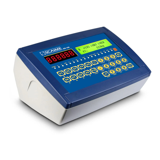
IPE100 indicator NU-IPE100-IO-USER-E-0212 3. INSTALLATION 3.1 IPE100 CASE AND DIMENSIONS ABS MODEL The indicator has an IP65 ABS case, whose external dimensions are shown in the Figure. It can be simply put on a table or fixed to a shelf or column available on request. -
Page 9: Power Supply
3.4 TURNING OFF THE INSTRUMENT TO TURN OFF the IPE100 keep the C key pressed until the “- OFF -“ message appears on the LED display and “ *** POWER OFF *** ” on the LCD display. -
Page 10: Turning On Printer In Energy Saving Mode
IPE100 indicator NU-IPE100-IO-USER-E-0212 3.5 TURNING ON PRINTER IN ENERGY SAVING MODE Premise: the SEtuP >> SEriAL >> CoMPrn >> PWrPrn parameter must be set as “EXt.oFF” or “PWrint”, TECHNICAL MANUAL). In a system where the indicator is connected to a printer, and both are battery powered, the printer is normally maintained in STAND-BY and powered only when a printout is needed. -
Page 11: 2Ndf" Key: Second Function Of The Keys
IPE100 indicator NU-IPE100-IO-USER-E-0212 - In the numeric or alphanumeric input phase, it enters, in this order, the following characters: . , ; : # < > \ | ” % & / ( ) = ? ^ ’ [ ] { };... -
Page 12: Entering Alphanumeric Text
IPE100 indicator NU-IPE100-IO-USER-E-0212 2ndF Net/Gross Conversion 2ndF Causes the display of the present metric scale information (see section 8). 2ndF TARE/ZERO Cyclical scale zero on the connected scales 2ndF Selection of remote scale 2ndF Selection of scale 1 2ndF Selection of scale 2... -
Page 13: Help Menu
IPE100 indicator NU-IPE100-IO-USER-E-0212 4.1.4 HELP MENU By pressing at length the HELP key it is possible to access a menu containing the list of keys with the relative function, and status (locked or unlocked) indication. F1:302 CUSTOMER DATABASES The display shows: - in the upper part: the key, followed by the code of the linked function in the <<... -
Page 14: Remote Control
IPE100 indicator NU-IPE100-IO-USER-E-0212 4.1.6 REMOTE CONTROL Depending on the model of indicator, it is possible to remotely control the instrument through one of the following types of remote controls: 18-key infrared (ir) or 6-key radio (rd). The type of remote control to be used must be selected in the Setup environment, in the << inF.Red >> step (TECHNICAL MANUAL). -
Page 15: Ipe100 Indicator Nu-Ipe100-Io-User-E
IPE100 indicator NU-IPE100-IO-USER-E-0212 4.1.6.2 “6-KEY” RADIO REMOTE CONTROL With this type of remote control, the functioning of each key can be programmed so that it is matched to one of the available keys of the indicator. This configuration must be carried out in the Setup environment, in the << inF.Red >> step (TECHNICAL MANUAL), after the selection of this type of remote control. -
Page 16: Function Display
2) STATUS INDICATORS (led pilot lights and / or graphic symbols) 3) DATA TARE: 1.000kg Figure 1: IPE100 displays NOTE: If the EEEEE message appears, this means that the value exceeds the maximum number of digits shown by the instrument. 4.2.1 STATUS INDICATORS... - Page 17 IPE100 indicator NU-IPE100-IO-USER-E-0212 SYMBOLS SHOWN ON THE LCD DISPLAY SYMBOL FUNCTION The weight detected by the weighing system is near the zero, included within the interval of –1/4 and +1/4 of the scale division. The weight is unstable. The displayed weight is a GROSS WEIGHT (depending on the software language).
-
Page 18: Battery Level Indication
IPE100 indicator NU-IPE100-IO-USER-E-0212 4.2.2 BATTERY LEVEL INDICATION The indicator is able to recognise whether it is powered by mains or by battery, and to indicate its charge level; to enable the battery level indication, one should configure the << bt.LEVEL >> step. -
Page 19: Selection Of The Scale
IPE100 indicator NU-IPE100-IO-USER-E-0212 5. SELECTION OF THE SCALE With various scales connected, press the 2ndF key followed by a key from 0 to 3: 0 >> Selection of remote scale. 1 >> Selection of scale number 1. 2 >> Selection of scale number 2. -
Page 20: Functioning With Remote Scale
IPE100 indicator NU-IPE100-IO-USER-E-0212 5.1 FUNCTIONING WITH REMOTE SCALE PREMISE: the functioning of the remote scale is foreseen with the use of independent channels (nuM.SCA step, TECHNICAL MANUAL.). The remote scale transmits in a continuous mode the weight string on a dedicated serial port (optional), in a unidirectional (from scale to indicator). -
Page 21: Scale Zero Function
IPE100 indicator NU-IPE100-IO-USER-E-0212 6. SCALE ZERO FUNCTION With various connected scales, select the scale using the numerical keyboard, using the 2ndF and the 0, 1, 2 and 3 keys. Keep the ZERO key pressed; the message "Zero" appears on the display after which: - If the weight on the scale is included in the percentage of capacity configured in the <<... -
Page 22: Locked / Unlocked Tare
IPE100 indicator NU-IPE100-IO-USER-E-0212 7.5 LOCKED / UNLOCKED TARE Normally, when a tare value has been entered (automatically, manually or from storage) by unloading the scale plate, the display shows the tare value with a negative sign (LOCKED TARE). One can also choose that the tare value is cancelled... -
Page 23: Display Of Metrologic Data (Info)
IPE100 indicator NU-IPE100-IO-USER-E-0212 9. DISPLAY OF METROLOGIC DATA (inFO) The indicator is fitted with a function named “INFO”, thanks to which it is possible to view the configuration metric data: First range capacity, first range minimum weigh, first range division. -
Page 24: Database
IPE100 indicator NU-IPE100-IO-USER-E-0212 11. DATABASE 11.1 CUSTOMERS The database is made up of 500 memory storages, identified by an index from 0 to 499, each having three 25-character descriptions; the entry / modification / cancellation of an element can be protected by a password; the unlocking procedure is described in section 12. -
Page 25: Cancellation
IPE100 indicator NU-IPE100-IO-USER-E-0212 11.1.3 CANCELLATION 1) Press the F1 key to access the database. 2) Select the storage to be deleted: - by using the arrow keys - by typing the storage number with the keyboard (the LCD display shows the first corresponding DESCRIPTION line) - by searching the first description (see section 11.1.7) -
Page 26: Entry, Modification And Quick Selection Of Customer 000
IPE100 indicator NU-IPE100-IO-USER-E-0212 To DESELECT the memory storage, one can proceed in two ways: 1) Press the F1 key to access the database. Press 2nd F, the LCD display shows: DESELECT CUSTOMER? Press ENTER key to confirm or another key to cancel. -
Page 27: Materials
IPE100 indicator NU-IPE100-IO-USER-E-0212 11.2 MATERIALS The database is made up of 500 memory storages, identified by an index from 0 to 499, each having two 20-character descriptions; the entry / modification / cancellation of an element can be protected by a password; the unlocking procedure is described in section 12. -
Page 28: Cancellation
IPE100 indicator NU-IPE100-IO-USER-E-0212 11.2.3 CANCELLATION 1) Press the F2 key to access the database. 2) Select the storage to be modified: - by using the arrow keys - by typing the storage number with the keyboard (the LCD display shows the first corresponding DESCRIPTION line) - by searching the first description (see section 11.2.7) -
Page 29: Entry, Modification And Quick Selection Of Material 000
IPE100 indicator NU-IPE100-IO-USER-E-0212 To DESELECT the memory storage, one may proceed in two ways: 1) Press the F2 key to access the database. Press 2nd F, the LCD display shows: DESELECT MATERIAL? Press ENTER to confirm or another key to cancel. -
Page 30: Vehicles
IPE100 indicator NU-IPE100-IO-USER-E-0212 11.3 VEHICLES The database is made up of 500 memory storages, identified by an index from 0 to 499, each having a license plate of 10 characters, one 20-character description and a tare value; the entry / modification / cancellation of an element can be protected by a password;... -
Page 31: Cancellation
IPE100 indicator NU-IPE100-IO-USER-E-0212 11.3.3 CANCELLATION 1) Press the F3 key to access the database. 2) Select the storage to be modified: - by using the arrow keys - by typing the storage number with the keyboard (the LCD display shows the first corresponding PLATE line) - by searching the plate (see section 11.3.7) -
Page 32: Entry, Modification And Quick Selection Of Vehicle 000
IPE100 indicator NU-IPE100-IO-USER-E-0212 At this point the memory storage will be linked to the weigh under way and will be printed if foreseen in the ticket. To DESELECT the memory storage, one can proceed in two ways: 1) Press the F3 key to access the database. -
Page 33: Database Access Password
13.1 GENERAL DESCRIPTION OF THE SYSTEM Besides the basic standard weighing function, the IPE100 allows to keep under control the flow of goods in input and output from a warehouse or a factory, with the possibility of simultaneously managing up to 999 vehicles, also on two scales; these vehicles can be managed as single vehicles or as vehicles with trailer. -
Page 34: Vehicle With Trailer
IPE100 indicator NU-IPE100-IO-USER-E-0212 13.2.1.2 VEHICLE WITH TRAILER (F.ModE >> totAL >> WEi.Mod step set on “SEC.WGt”, TECHNICAL MANUAL.) - Position the vehicle on the scale. - Select, if requested, the customer / material / vehicle to be linked to the weigh. -
Page 35: Output Weigh
IPE100 indicator NU-IPE100-IO-USER-E-0212 13.2.2 OUTPUT WEIGH 13.2.2.1 SINGLE VEHICLE (F.ModE >> totAL >> WEi.Mod step set on “nor.WGt”, TECHNICAL MANUAL.) - Position the vehicle on the scale. - Select, if requested, the customer / material / vehicle to be linked to the weigh. -
Page 36: Weighing Through Vehicle License Plate
IPE100 indicator NU-IPE100-IO-USER-E-0212 Confirm with ENTER or press another key to cancel. • If no input weigh has been made, if one then enters the menu of the “open” weighs, the indicator will show on the LCD display “NO OPEN WEIGHS IN INPUT” and will emit a prolonged sound; then it will cancel the weigh and return to weighing. -
Page 37: Vehicle With Trailer
IPE100 indicator NU-IPE100-IO-USER-E-0212 Enter the license plate number and press ENTER. 1) Press F7, the LCD display will show: INSERT PLATE Press ENTER, one enters the menu of the “open” input weighs: CM884FK 995kg Select the desired weigh using the arrow keys . -
Page 38: Conditions For Totalisation
IPE100 indicator NU-IPE100-IO-USER-E-0212 Confirm with ENTER or press another key to cancel. • If no input weigh has been made, if one then enters the menu of the “open” weighs, the indicator will show on the LCD display “NO OPEN WEIGHS IN INPUT” and will emit a prolonged sound; then it will cancel the weigh and return to weighing. -
Page 39: Reenabling The Printing And Input / Output Weigh
IPE100 indicator NU-IPE100-IO-USER-E-0212 13.7 REENABLING THE PRINTING AND INPUT / OUTPUT WEIGH After having carried out an input/output weigh or a single weigh, in order to carry out a new one, the displayed weight must pass by the zero or become unstable. -
Page 40: Ticket Progressive
IPE100 indicator NU-IPE100-IO-USER-E-0212 NOTE: The number of settable digits DOES NOT INCLUDE the comma. 13.9.2 TICKET PROGRESSIVE Through function 402, combinable with the desired key (<< F.KEYS >> step, TECHNICAL MANUAL.), it’s possible to modify or clear the TICKET PROGRESSIVE (up to 5 digits). - Page 41 IPE100 indicator NU-IPE100-IO-USER-E-0212 CUSTOMER TOTAL - Programmable printout - By pressing the 2nd F key followed by F1, the CUSTOMER TOTAL is printed and then cleared as well as the printing of the format linked to the S.F.08 function. Please find below the default printout:...
-
Page 42: Linking Of The Formats To The Print Functions
IPE100 indicator NU-IPE100-IO-USER-E-0212 GRAND TOTAL - Programmable printout - By pressing the F10 key the PARTIAL TOTAL is printed and then cleared as well as the printing of the format linked to the S.F.04 function. START-UP PRINTOUT - Programmable printout - When turning on the indicator, the printout of the format linked to the S.F.11 function is made;... -
Page 43: Quick Linking Of The Formats
IPE100 indicator NU-IPE100-IO-USER-E-0212 in which: XX indicates the number of the format to be linked. • Type the format number and press ENTER. NOTE: In order to no link any format to a vector one should enter the number 00. -
Page 44: Other Functions
IPE100 indicator NU-IPE100-IO-USER-E-0212 15. OTHER FUNCTIONS 15.1 CALCULATOR Through function 114 combinable with the desired key (<< F.KEYS >> step, TECHNICAL MANUAL.), one enables the calculator function. • ADDITION • MULTIPLICATION • SUBTRACTION Procedure: - Enter the first value using the numerical keyboard. -
Page 45: Normal Functioning Mode
IPE100 indicator NU-IPE100-IO-USER-E-0212 15.4.1 NORMAL FUNCTIONING MODE By setting the SEtuP >> outPut >> r.ModE parameter on “norMAL”, one configures the independent use of the outputs: - the check is always made on all the set outputs - the enabling of one of these does not provoke the disabling of the others. -
Page 46: Instability
IPE100 indicator NU-IPE100-IO-USER-E-0212 15.4.1.5 INSTABILITY By selecting this functioning mode, the output function on the unstable weight is enabled. 15.4.1.6 TOTALISATION By selecting this functioning mode, the output function is enabled after executing a single weigh or after an output weight (at the end of an input/output cycle);... -
Page 47: Weight Acquisition
IPE100 indicator NU-IPE100-IO-USER-E-0212 15.4.1.12 WEIGHT ACQUISITION By selecting this functioning mode, the output function is enabled after the weight acquisition; the relay remains enabled until the weigh is restored; in other words, by the passing by zero of the net weight or by weight instability (see F.ModE >>... -
Page 48: Exclusive Functioning Mode
IPE100 indicator NU-IPE100-IO-USER-E-0212 SCALE 2 R3, functioning with control light for the second scale, normally CLOSED, ENABLING SET POINT 10kg. GREEN R4, functioning with control light for second scale, normally OPEN, ENABLING SET POINT 10kg. 15.4.2 EXCLUSIVE FUNCTIONING MODE By setting the SEtuP >>... -
Page 49: Com Data Diagnostic
IPE100 indicator NU-IPE100-IO-USER-E-0212 15.6 COM DATA DIAGNOSTIC Through function 119 combinable with the desired key (<< F.KEYS >> step, TECHNICAL MANUAL.), one enables the Com data diagnostic function. The display shows: 119 COM. DAT 119 COM. DAT ● ● COM1 (PC) ASCII ○... -
Page 50: Reading Of The Weighs Carried Out
IPE100 indicator NU-IPE100-IO-USER-E-0212 With each storage, the weigh number is increased of 000001; when it reaches the value 131071, it restarts from 000000 and the rewriting number increases of 00001. If the weigh can not be saved in the alibi, the numeric ID will be substituted with the message "NO". -
Page 51: String Format (Weight/Id)
IPE100 indicator NU-IPE100-IO-USER-E-0212 16.2.2 STRING FORMAT (WEIGHT/ID) The PID string contains all the information regarding the executed weigh. DESCRIPTION OF THE PID STRING: [II]PIDSS,B,LLLLLLLLLLUU,YYTTTTTTTTTTUU,(ID | NO) <CR or CRLF> in which: [II] 485 address (only in the case of 485 transmission mode) -
Page 52: Messages
IPE100 indicator NU-IPE100-IO-USER-E-0212 17. MESSAGES While using the indicator, it is possible to incur into the following errors: 17.1 INSIDE THE SETUP OR MENU OR AT START-UP VISUALIZATION DESCRIPTION During the calibration some internal negative points have been calculated: CALIBRATION Err. -
Page 53: In Weighing
IPE100 indicator NU-IPE100-IO-USER-E-0212 17.2 IN WEIGHING MESSAGE DESCRIPTION WEIGHT UNDER It is shown in the LCD display when one tries to print or totalise with the 0 or negative weight. 20 DIVISIONS NO ZERO CROSS OR Printing or totalisation not possible without having the weight pass by the net zero or by INSTABILITY instability. -
Page 54: Declaration Of Conformity
IPE100 indicator NU-IPE100-IO-USER-E-0212 DECLARATION OF CONFORMITY This device conforms to the essential standards and norms relative to the applicable European regulations. WARRANTY The warranty period begins on the day the instrument is delivered. It includes spare parts and labour for repairs at no charge if the INSTRUMENTS ARE RETURNED prepaid to the DEALER’S PLACE OF BUSINESS.
Need help?
Do you have a question about the IPE100 and is the answer not in the manual?
Questions and answers
Scaime IPE100. WEIGHT OUT OF THRESHOLD
"Weight out of threshold" for the Scaime IPE100 means that the measured weight is outside the preset allowable range. This range is defined by a minimum and maximum threshold, which can be set using the "thr.Lo" (lower threshold) and "thr.hi" (upper threshold) settings. If the weight falls outside this range when the F6 or F7 key is pressed, the display will show the message "WEIGHT OUT OF THRESHOLD" for a few seconds, and the operation will not be accepted.
This answer is automatically generated
Hello, my scale does not accept a weight over 500 kg. I think it was set incorrectly. What should I do?
To reset the weight limit on a Scaime IPE100 scale to accept weights over 500 kg, follow these steps:
1. Access the Maximum Threshold Setting menu:
- Use function 500 (combinable with the desired key) to enter the "thr.hi" menu.
- Set the upper totalisation threshold to a value above 500 kg.
- Press ENTER to confirm.
2. Ensure the Minimum Threshold Setting is appropriate:
- Use function 501 to enter the "thr.Lo" menu.
- Set the lower totalisation threshold as needed.
- Press ENTER to confirm.
3. If you want to disable the weight limit entirely:
- Set 0 in the Maximum Threshold to allow totalisation up to the scale’s maximum capacity.
- Setting 0 in both thresholds disables the restriction.
After making these changes, the scale should accept weights over 500 kg.
This answer is automatically generated