Advertisement
VERIS INDUSTRIES
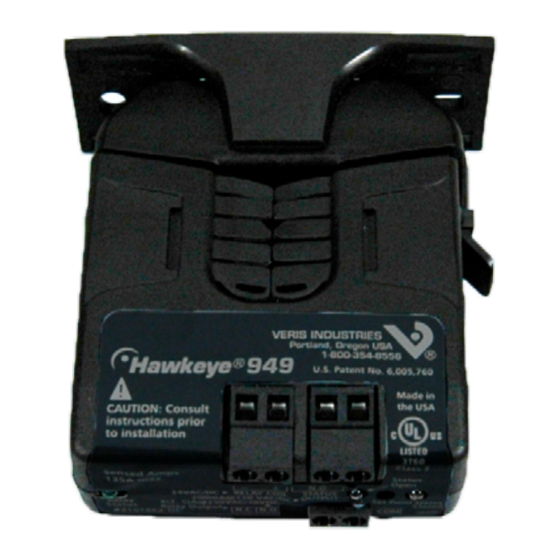
H949
DANGER
HAZARD OF ELECTRIC SHOCK, EXPLOSION, OR ARC FLASH
• Follow safe electrical work practices. See NFPA 70E in the USA, or applicable local codes.
• This equipment must only be installed and serviced by qualified electrical personnel.
• Read, understand and follow the instructions before installing this product.
• Turn off all power supplying equipment before working on or inside the equipment.
• Use a properly rated voltage sensing device to confirm power is off.
DO NOT DEPEND ON THIS PRODUCT FOR VOLTAGE INDICATION
• Only install this product on insulated conductors.
Failure to follow these instructions will result in death or serious injury.
NOTICE
• This product is not intended for life or safety applications.
• Do not install this product in hazardous or classified locations.
• The installer is responsible for conformance to all applicable codes.
• Mount this product inside a suitable fire and electrical enclosure.
Wiring ExamplE
CONTACTOR
Motor
Z201502-0A
PAGE 1
Alta Labs, Enercept, Enspector, Hawkeye, Trustat, Veris, and the Veris 'V' logo are trademarks or registered trademarks of Veris Industries, L.L.C. in the USA and/or other countries.
All manuals and user guides at all-guides.com
CURRENT MONITORING
CONTROLLER
DO
(Relay
Coil)
DI
(Status)
CONTROL
POWER
Fan or Pump
©2009 Veris Industries USA 800.354.8556 or +1(0)503.598.4564 / support@veris.com
INSTALLATION GUIDE
Split-Core Current Switch, High Voltage Output,
with Command Relay
Installer's Specifications
Sensor Power
Insulation Class
Frequency Range
Temperature Range
Humidity Range
Hysteresis
Terminal Block Maximum Wire Size
Terminal Block Torque (nominal)
Agency Approvals
Do not use the LED status indicators as evidence of applied voltage.
quick install
1.
Disconnect and lock out power to the conductor to be monitored.
2.
Plan the installation:
Locate a mounting surface for the removable mounting bracket that will allow
the monitored conductor to pass through the iris, or "window" when it is installed
and keep the product at least 1/2" (13mm) from any uninsulated conductors (CE).
Determine cable routing for the controller connection, allowing wiring to reach
the mounting location.
3.
Install mounting bracket
Drill holes to mount the bracket to the chosen surface using the included screws.
4.
Wire the output connections between the sensor and the controller.
5.
Snap thesensor over the wire to be monitored and clip the assembly to the
mounting bracket.
6.
Close up and power up.
DimEnsions
Removable Mounting Bracket
1.1"
(26 mm)
(21 mm)
3.1"
(79 mm)
(70 mm)
Ø = 0.3"
(8 mm)
3.0"
(76 mm)
949
Induced from monitored conductor
-15° to 60°C (5° to 140°F)
10-90% RH, non-condensing
4 in-lbs (0.45 N-m)
UL 508 open device listing
1.0"
(25 mm)
Bracket can be mounted
on either side for added
0.8"
installation flexibility.
Self-gripping
Iris
2.8"
Use DIN Rail
1.4"
Mounting clip
(36 mm)
(Veris part
2.5"
number AH01) to
(64 mm)
mount on stan-
dard DIN rail.
600VAC RMS
50/60Hz
10% Typical
14 AWG
07091
Advertisement
Table of Contents

Related Manuals for Veris Industries Hawkeye 949


Summary of Contents for Veris Industries Hawkeye 949
- Page 1 Z201502-0A PAGE 1 ©2009 Veris Industries USA 800.354.8556 or +1(0)503.598.4564 / support@veris.com 07091 Alta Labs, Enercept, Enspector, Hawkeye, Trustat, Veris, and the Veris ‘V’ logo are trademarks or registered trademarks of Veris Industries, L.L.C. in the USA and/or other countries.
- Page 2 Z201502-0A PAGE 2 ©2009 Veris Industries USA 800.354.8556 or +1(0)503.598.4564 / support@veris.com 07091 Alta Labs, Enercept, Enspector, Hawkeye, Trustat, Veris, and the Veris ‘V’ logo are trademarks or registered trademarks of Veris Industries, L.L.C. in the USA and/or other countries.
Need help?
Do you have a question about the Hawkeye 949 and is the answer not in the manual?
Questions and answers