Table of Contents
Advertisement
Quick Links
Advertisement
Table of Contents

Related Manuals for IFM Electronic efector300 SBU3


Summary of Contents for IFM Electronic efector300 SBU3
- Page 1 Operating instructions Mechatronic flow sensor SBU3...
-
Page 2: Table Of Contents
Contents 1 Safety instructions ....................2 2 Functions and features ..................3 3 Installation......................3 4 Electrical connection ....................4 5 Switch point setting ....................4 5.1 Definition of requested value .................5 5.2 Adjustment to existing flow ................5 6 Operation ......................6 7 Maintenance, repair and disposal ................6 8 Scale drawing ......................7 9 Technical data .....................8 1 Safety instructions... -
Page 3: Functions And Features
2 Functions and features The unit monitors liquid media. It detects the volumetric flow quantity to the principle of differential pressure and switches the output: • Output closed (LED = ON), if volumetric flow quantity ≥ switch point. • Output open (LED = OFF), if volumetric flow quantity < switch point. The switch point is adjustable. -
Page 4: Electrical Connection
4 Electrical connection The unit must be connected by a qualified electrician. The national and international regulations for the installation of electrical equipment must be adhered to. Voltage supply to EN 50178, SELV, PELV. ► Disconnect power. ► Connect the unit as follows: For information about available sockets/connectors see: www.ifm.com → Products → Accessories 5 Switch point setting... -
Page 5: Definition Of Requested Value
5.1 Definition of requested value ► Loosen the lock nut. ► Turn the knurl until the requested value just becomes visible on the setting scale. → Example in figure 2: requested value = 10 l/min. ► Tighten the lock nut. 5.2 Adjustment to existing flow ► Let the normal flow circulate in the installation. ►... -
Page 6: Operation
6 Operation After power on the unit is ready for operation. It detects the volumetric flow quanti- ty and switches the output according to the setting. Function diagram A = requested flow; B = switch point; C = switching output 7 Maintenance, repair and disposal In case of correct use no maintenance and repair measures are necessary. -
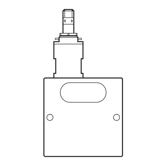
Page 7: Scale Drawing
8 Scale drawing... -
Page 8: Technical Data
9 Technical data Setting range - SBU323 [l/min] ....................... 0.3...25 - SBU324 [l/min] ....................... 0.3...50 - SBU325 [l/min] ....................... 0.3...75 Operating voltage [V] ............... 24 DC (-15 % / +10 %) Current rating [mA] ......................100 Protected against short circuits, reverse polarity and overload Voltage drop [V] ......................<...