Table of Contents
Advertisement
Quick Links
Advertisement
Table of Contents

Subscribe to Our Youtube Channel
Related Manuals for IFM Electronic efector300 SU9004


Summary of Contents for IFM Electronic efector300 SU9004
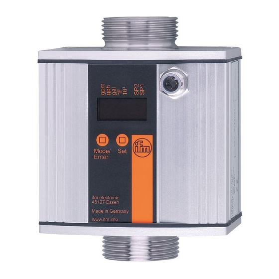
- Page 1 Operating instructions Ultrasonic flow rate sensor SU9004...
-
Page 2: Table Of Contents
Contents 1 Preliminary note ���������������������������������������������������������������������������������������������������4 1�1 Symbols used ������������������������������������������������������������������������������������������������4 1�1 Warning signs used ���������������������������������������������������������������������������������������4 2 Safety instructions �����������������������������������������������������������������������������������������������5 3 Functions and features ����������������������������������������������������������������������������������������6 4 Function ���������������������������������������������������������������������������������������������������������������7 4�1 Process measured signals ����������������������������������������������������������������������������7 4�2 Volumetric flow monitoring �����������������������������������������������������������������������������7 4�3 Temperature monitoring ���������������������������������������������������������������������������������7 4�4 Analogue function ������������������������������������������������������������������������������������������7 4�5 Customer-specific calibration (CGA) �������������������������������������������������������������8 5 Installation������������������������������������������������������������������������������������������������������������9... - Page 3 10�4�4 Calibrate the curve of measured values for volumetric flow �������������19 10�4�5 Reset calibration data �����������������������������������������������������������������������19 10�4�6 Set the measured value damping for volumetric flow �����������������������19 10�4�7 Set output status in fault condition ����������������������������������������������������19 10�4�8 Select the medium to be monitored ��������������������������������������������������20 10�5 Service functions ���������������������������������������������������������������������������������������20 10�5�1 Read min/max values for volumetric flow �����������������������������������������20 10�5�2 Read the min/max values for the temperature ���������������������������������20...
-
Page 4: Preliminary Note
1 Preliminary note 1.1 Symbols used ► Instructions > Reaction, result […] Designation of keys, buttons or indications → Cross-reference Important note Non-compliance may result in malfunction or interference� 1.1 Warning signs used CAUTION Warning of personal injury� Slight reversible injuries may result�... -
Page 5: Safety Instructions
2 Safety instructions • Read this document prior to set-up of the unit� Ensure that the product is suit- able for your application without any restrictions� • If the operating instructions or the technical data are not adhered to, personal injury and/or damage to property can occur�... -
Page 6: Functions And Features
3 Functions and features Pressure Equipment Directive (PED): The units comply with section 3, article 3 of the Directive 97/23/EC and must be designed and manufactured for non-super- heated liquids of group 2 fluids in accordance with the sound engineering practice� The unit monitors liquid media�... -
Page 7: Function
4 Function 4.1 Process measured signals The unit displays the current process values� It generates 2 output signals according to the parameter setting� - OUT1: Analogue signal for temperature limit value (→ 10.2) - OUT2: Analogue signal for volumetric flow limit value (→ 10.3) 4.2 Volumetric flow monitoring The volumetric flow is monitored by an ultrasonic measuring system, the meas- ured signals are evaluated by the electronics�... -
Page 8: 4�5 Customer-Specific Calibration (Cga)
Minimum distance between ASP and AEP = 20 % of the measuring range� In the set measuring range the output signal is between 4 and 20 mA� For an output signal > 20 mA the volumetric flow quantity is above the final value of the measuring range�... -
Page 9: Installation
5 Installation ► Avoid deposits, accumulated gas and air in the pipe system� 5.1 Recommended mounting position ► Install the unit in that section of the plant where the medium flows under pres- sure� This avoids disturbance by air bubbles� ►... -
Page 10: 5�2 Non Recommended Installation Position
5.2 Non recommended installation position ► Avoid the following installation positions: Directly in front of a falling pipe� In a falling pipe� At the highest point of the pipe Directly in front of the spout of the system� pipe� Flow rate direction horizontal, unit On the suction side of a pump�... -
Page 11: 5�3 Installation In Pipes
5.3 Installation in pipes The unit can be installed in pipes using adapters� Information about the available adapters at www�ifm�com� Flow direction 1� Screw the adapter (B) into the pipe (A)� 2� Place the seals (C) and install the unit according to the marked flow direction� ►... -
Page 12: Electrical Connection
6 Electrical connection The unit must be connected by a qualified electrician� The national and international regulations for the installation of electrical equipment must be adhered to� Voltage supply according to EN 50178, SELV, PELV� ► Disconnect power� ► Connect the unit as follows: BK: black BN: brown BU: blue... -
Page 13: Operating And Display Elements
7 Operating and display elements 1 2 3 4 5 6 7 8 Mode /Enter 1 to 8: Indicator LEDs - LED 1 = current volumetric flow in litres / minute� - LED 2 = current volumetric flow in cubic metres / hour� - LED 3 = current volumetric flow in gallons / minute (gpm)�... -
Page 14: Menu
8 Menu 8.1 Menu structure l/min °C/°F °C/°F Mode/Enter... -
Page 15: 8�2 Explanation Of The Menu
8.2 Explanation of the menu ASP1 Analogue start value for temperature� AEP1 Analogue end value for temperature� ASP2 Analogue start value for volumetric flow� AEP2 Analogue end value for volumetric flow� Extended functions / opening of menu level 2� HI�F Maximum value memory for volumetric flow� LO�F Minimum value memory for volumetric flow�... -
Page 16: Set
9 Set-up After power on and expiry of the power-on delay time of approx� 10 s the unit is in the Run mode (= normal operating mode)� It carries out its measurement and eval- uation functions and generates output signals according to the set parameters� • During the power-on delay time the outputs are switched as programmed: - ON with normally open function (Hno / Fno) - OFF with normally closed function (Hnc / Fnc)�... -
Page 17: 10�1 Parameter Setting In General
10.1 Parameter setting in general 3 steps must be taken for each parameter setting: Select parameter ► Press [Mode/Enter] until the re- quested parameter is displayed. Mode /Enter Set parameter value ► Press and hold [Set]� > Current setting value of the param- eter flashes for 5 s�... -
Page 18: 10�1�2 Locking / Unlocking
10.1.2 Locking / unlocking The unit can be locked electronically to prevent unintentional settings� Locking: ► Make sure that the unit is in the normal operating mode� ► Press [Mode/Enter] + [Set] for 10 s� Mode /Enter > [Loc] is displayed� During operation: [LOC] is briefly displayed if you try to change parameter values�... -
Page 19: 10�4�2 Set The Standard Unit Of Measurement For Temperature
10.4.2 Set the standard unit of measurement for temperature ► Select [Uni�T] and set the unit of measurement: [°C] or [°F]� 10.4.3 Configuration of the standard display ► Select [SELd] and determine the standard measuring unit: - [FLOW] = the current volumetric flow value in the standard unit of measurement is displayed�... -
Page 20: 10�4�8 Select The Medium To Be Monitored
10.4.8 Select the medium to be monitored ► Select [MEDI] and set the requested medium: - [H2O] = water� - [GLYC] = glycol solutions� - [OIL�1] = high viscosity oil (30���68 mm²/s at 40°C; 30���68 cSt at 104°F) - [OIL�2] = low viscosity oil (7���40 mm²/s at 40°C; 7���40 cSt at 104°F) 10.5 Service functions 10.5.1 Read min/max values for volumetric flow ►... -
Page 21: Operation
11 Operation 11.1 Read the process value The LEDs 1-6 signal which process value is currently displayed� The process value to be displayed as standard (temperature or volumetric flow) can be preset → 10.4.3 Configuration of the standard display). A standard unit of measurement can be defined for the flow velocity and the tem- perature (→ 10.4.1 and → 10.4.2). -
Page 22: 11�4 Fault Indications
11.4 Fault indications [SC1] Short circuit in OUT1� [SC2] Short circuit in OUT2� [SC] Short circuit in both outputs� [OL] Detection zone of volumetric flow or temperature exceeded� Measured value between 120 % and 130 % of the final value of the measuring range�... -
Page 23: Factory Setting
13 Factory setting Factory setting User setting -10.0 ASP1 80.0 AEP1 ASP2 200.0 AEP2 FOU1 FOU2 Lmin Uni.F °C Uni.T FLOW SELd MEDI More information at www�ifm�com...
Need help?
Do you have a question about the efector300 SU9004 and is the answer not in the manual?
Questions and answers