Advertisement
- 1 General safety instructions
- 2 Functional description
- 3 Areas of application
- 4 Mounting the module
- 5 Operation
- 6 Start-up
- 7 Starting-up with the Gira Keyless In app
- 8 Technical data
-
9
Manual start-up
- 9.1 Commands for teaching in and deleting taught-in fingers
- 9.2 Commands for configuring the fingerprint module
- 9.3 Commands for use without door communication system
- 9.4 Commands for assignments in the door communication system: Assign switching actuator
- 9.5 Commands for assignments in the door communication system: Assign door-opener
- 10 Overview of administrators
- 11 Conformity
- 12 Warranty
- 13 Gira
- 14 Documents / Resources

General safety instructions

Electrical devices may only be installed and connected by a qualified electrician!
These instructions are an integral part of the product and must remain with the end customer.
Required accessories
- System 106 surface-mounted housing,
1-gang to 5-gang (item no. 5501...,
5502..., 5503..., 5504..., 5505...) or System 106 flush housing, 1-gang to 5gang (item no. 5511..., 5512..., 5513...,
5514..., 5515...)
Accessories
- System 106 voice module (item no.
5563..) with call-button module
(553. ..) or door station module (item no. 5565 9.). - Video control device (item no. 1288 00) or audio control device (item no.1278 00).
- Gira home station
- Power supply for door communication DC 24 V 300 mA (item no. 1296 00).
Functional description
The fingerprint module serves as access control based on biometric characteristics of human fingers. Up to 100 fingers can be taught in. The module can be operated as an individual device or integrated into the Gira door communication system.
Scope of delivery
1 x System 106 door fingerprint module
1 x safety card
1 x operating instructions
Ensure the package contents are complete and undamaged. Please see "Warranty" in the case of any defects. Device description
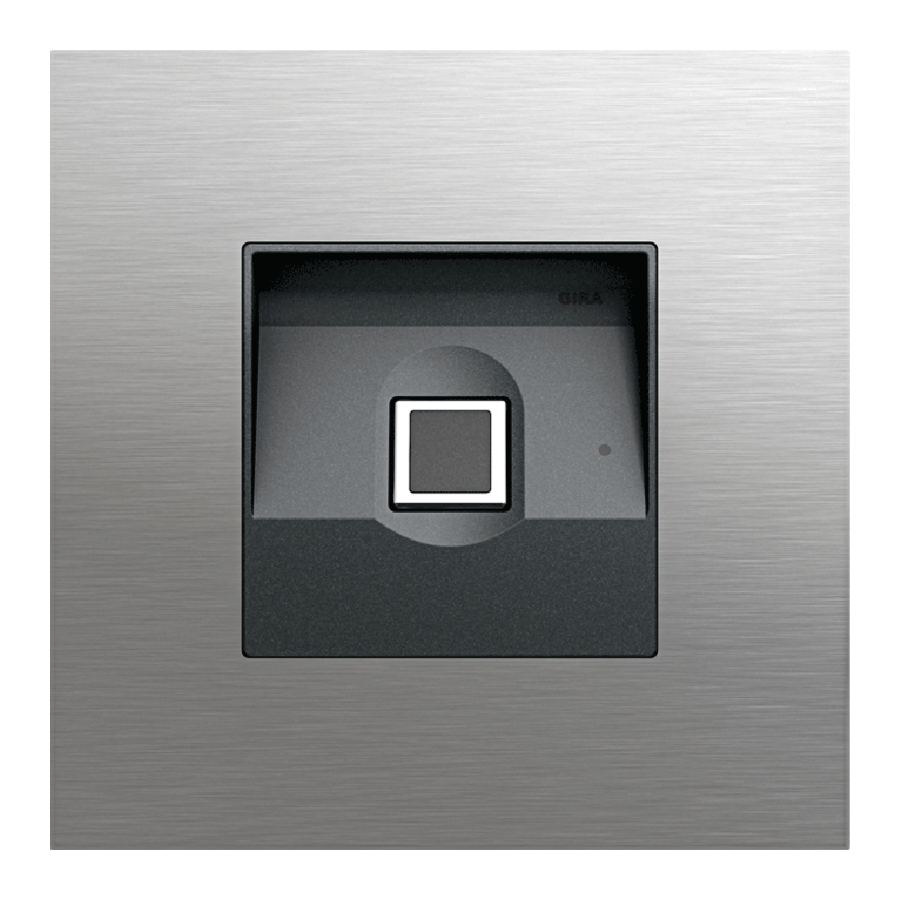
Front view

- Front plate
- Sensor
Rear view

- Turning bolt (4x)
- Socket (2x): System cable
- Mounting (4x): Module front
- Screw terminal: TC bus and additional power supply
Areas of application
Use without door communication system
If the fingerprint module is only to be used to trigger switching actions or to open doors without an accompanying speech or video connection, installation without a full door communication system is possible: Instead of a control device, the fingerprint module bus interface can be used, for example, to supply switching actuators, button interfaces or other Keyless In devices. Devices for voice or video connections cannot be connected.
A DC 24 V 300 mA power supply is connected to the additional power supply (AS) terminals of the fingerprint module to supply the devices. Its voltage is then fed to the TC bus, to which the remaining devices are connected. The bus supply must be activated in the Keyless In app or directly on the device when starting-up the fingerprint module.
Due to the devices' different power consumption, the devices sometimes count as multiple devices:
- DCS switching actuator: 1 device
- Button interface: 1 device
- Additional Keyless In devices: 7 devices
When selecting devices, do not exceed the maximum number of 20 devices.
The maximum cable lengths from the DC 24 V additional power supply via the fingerprint module to the last device are as follows:
- 100 m with 0.6 mm wire diameter
- 150 m with 0.8 mm wire diameter
The supplying fingerprint module can be located at any point.

- Power supply DC 24 V 300 mA
- System 106 fingerprint module, supplying the TC bus
- System 106 fingerprint module
- DCS switching actuators
- Button interface
The TC bus is connected to the fingerprint module bus terminals. The DC 24 V power supply is connected to the AS terminals. Only one Keyless In module may be connected to this DC 24 V power supply. The TC bus supply must be activated during start-up. After a factory reset, the TC bus supply is deactivated.
Use as a stand-alone module in the door communication system
The fingerprint module can be operated in the door communication system independently of door stations.

- Control device
- DC 24 V power supply
- Home station
- System 106 fingerprint module
- DCS switching actuator
The connection to the TC bus is made using the "Bus" screw terminals. An additional power supply can be connected to the "AS" screw terminals.
If no additional power supply is connected, the fingerprint module reduces the maximum possible number of devices depending on the control device used as follows:
- Audio control device: The fingerprint module replaces 16 audio devices.
- Video control device: The fingerprint module replaces 10 audio or 4 video devices.
Use in a System 106 door station
The system cable can be used to connect the fingerprint module to System 106 modules and the door communication system. This way, the fingerprint module can, for example, trigger a switching action from a switching actuator.

- System 106 door station with fingerprint module
- Surface-mounted video home station 7
- Video control device
- DCS switching actuator
- Home station
Power is supplied via the "System" connection.
 Do not assign screw terminals
The fingerprint module screw terminals "AS" and "Bus" must not be occupied.
If no additional power supply is connected, the fingerprint module reduces the maximum possible number of devices depending on the control device used as follows:
- Audio control device: The fingerprint module replaces 16 audio devices.
- Video control device: The fingerprint module replaces 10 audio or 4 video devices.
Protecting the control device
against unauthorised access
In areas requiring a high level of security, the control device should be secured (locked) against unauthorized access.
Mounting the module
Mounting the module
The following steps can be found in the mounting instruction for the System 106 surface-mounted housing 1- to 5-gang or flush-mounted housing 1- to 5-gang:
- Lock the module on the mounting frame.
- Connect the system cable.
- Place terminating resistors
- Swivel the function carrier into the surface-mounted housing and screw it in place.
Operation
It is only necessary to place the previously taught-in finger once on the module to operate fingerprint module.
Touch with finger
To ensure the fingerprint module functions properly, the finger must be correctly positioned during both the teaching in process and subsequent operation.
Ideally:
Place the area with the strongest fingerprint swirl (the centre of the fingertip) centrally on the sensor.

False

Acknowledgement signals
| LED | Tone | Meaning |
| lights up green | 1x long | positive acknowledgement signal, e.g.:
|
| flashes green | - | Device is in delivery state |
| lights up red | 3 x short | negative acknowledgement signal, e.g.:
|
| lights up orange | - | Administrator mode or SysProg is active |
| lights up blue | - | Bluetooth connection active |
| lights up red | 4 x short | A negative acknowledgement signal for an access attempt outside the permitted time period in the case of a time-limited access authorization |
Acknowledgement tone off
If the acknowledgement tone is switched off, no acknowledgement tones sound. The acknowledgement signals are given solely by the LED.
Start-up
The fingerprint module can be put into operation and configured using the Gira Keyless In app or manually on the device. When starting operation, you must choose an operating mode. Subsequent changes are only possible with additional effort.
Starting-up with the Gira Keyless In app
- Download the Gira Keyless In app to theadministrator's mobile device:
- Start the app and follow the instructionson the screen.
Activation code
The activation code required for start-up can be found on the enclosed safety card.
Starting-up without the app
If you want to perform start-up manually, please refer to the instructions on the next page.
Technical data
| Power supply: | via system (flat ribbon cable, 10-pole ) or via control device or via AS (DC 24 V 300 mA) |
| Power intake | |
| Stand-by mode: | 650 mW |
| Connections: | 2 x system 2 x additional supply 2 x 2-wire bus |
| Ambient temperature: | -25°C to +70°C |
| Protection type: | IP54 |
| Dimensions (W x H): | 106.5 x 106.5 mm |
| Radio frequency: | 2.402 -2.480 GHz |
| Transmission capacity: | max. 2,5 mW, Class 2 |
| Transmitting range: | typ. 10 m |
Manual start-up
Start-up is carried out using the following steps:
- Teach in first administrator
- Teach in user finger
- Configure fingerprint module
- for use in the door communication system: Assign door-opener / switching actuators
Detailed start-up instructions
Detailed instructions for manual start-up can be found in the Gira download section under:

Basics for teaching in a finger
- Place the finger to be taught in in themiddle of the sensor until the short acknowledgement tone sounds.

- As soon as the LED lights up orange, place the finger on the sensor again.
- Repeat steps 1 to 2 several times.
- The finger is taught in when a long acknowledgement tone sounds and the LED lights up green.

For "difficult" fingers, e.g. if a person has very dry skin, it may be necessary to place the finger to be taught-in up to 7 times. If 3 short tones sound after the seventh attempt, the finger has not been successfully taught in.
In this case, place the finger again (step 1) or use another finger.
Commands for teaching in and deleting taught-in fingers
You can mark the taught in fingers in the table on the right hand side.

Commands for configuring the fingerprint module

Commands for use without door communication system

Commands for assignments in the door communication system: Assign switching actuator

Commands for assignments in the door communication system: Assign door-opener

Overview of administrators

User finger overview


Conformity
Gira Giersiepen GmbH & Co. KG hereby declares that the radio system type art. no. 5551.. meets the directive 2014/53/EU. You can find the full article number on the device. The complete text of the EU Declaration of Conformity is available under the Internet address: www.gira.de/konformitaet
Warranty
The warranty is provided in accordance with the statutory requirements via the retailer. Please submit or send faulty devices postage paid and with a fault description to your sales representative (retailer / installation company / electronics retailer). This person will forward the devices to the Gira Service Centre.
Gira
Gira
Giersiepen GmbH & Co KG
Elektro-Installations-Systeme
P.O. Box 1220
42461 Radevormwald, Germany
Phone: +49 2195 602 - 0
Fax: +49 2195 602 - 191
info@gira.de
www.gira.de

Documents / Resources
References
Download manual
Here you can download full pdf version of manual, it may contain additional safety instructions, warranty information, FCC rules, etc.
Advertisement


Need help?
Do you have a question about the System 106 Fingerprint Module 5551 and is the answer not in the manual?
Questions and answers